Sun Microsystems Netra T2000 Installation Manual
Netra t2000 server installation guide
Hide thumbs
Also See for Netra T2000:
- Administration manual (122 pages) ,
- Service manual (166 pages) ,
- Service manual (138 pages)

Related Manuals for Sun Microsystems Netra T2000


Summary of Contents for Sun Microsystems Netra T2000
- Page 1 Netra T2000 Server ™ Installation Guide Sun Microsystems, Inc. www.sun.com Part No. 819-5838-10 September 2006, Revision A Submit comments about this document at: http://www.sun.com/hwdocs/feedback...
- Page 2 Products bearing SPARC trademarks are based upon an architecture developed by Sun Microsystems, Inc. The OPEN LOOK and Sun™ Graphical User Interface was developed by Sun Microsystems, Inc. for its users and licensees. Sun acknowledges the pioneering efforts of Xerox in researching and developing the concept of visual or graphical user interfaces for the computer industry. Sun holds a non-exclusive license from Xerox to the Xerox Graphical User Interface, which license also covers Sun’s licensees who implement OPEN...
-
Page 3: Table Of Contents
Contents Server Views 1 Server Features 3 Chip-Multitheaded Multicore Processor and Memory Technology 4 Performance Enhancements 5 Preinstalled Solaris Operating System 5 Preloaded Java Enterprise System Software 6 Hardware-Assisted Cryptography 7 Remote Server Management With ALOM 7 System Reliability, Availability, and Serviceability 8 Hot-Swappable Components 8 Power Supply Redundancy 9 Fan Redundancy 9... - Page 4 Connecting Cables 69 ▼ To Connect the Ethernet Network Cables 69 ▼ To Connect the SC Serial Management Port 70 ▼ To Connect the SC Network Management Port 71 Input Power Cables 72 Netra T2000 Server Installation Guide • September 2006...
- Page 5 TTYA Serial Port 72 USB Ports 73 Alarm Port 74 Managing Cables With the CMA 75 ▼ To Open and Close a Cable Clip 75 ▼ To Move a Cable Clip 76 Powering On the Server for the First Time 77 ▼...
- Page 6 Netra T2000 Server Installation Guide • September 2006...
- Page 7 Figures Netra T2000 Server Front Panel 1 FIGURE 1-1 Netra T2000 Server Rear Panel 2 FIGURE 1-2 Netra T2000 Server 2 FIGURE 1-3 UltraSPARC T1 Multicore Processor Block Diagram 5 FIGURE 1-5 Finger Holds on Bezel 16 FIGURE 2-1 Installing the Air Filter in the Bezel 17...
- Page 8 Installing and Securing the Server in the 2-Post Rack 59 FIGURE 4-4 Installing a Screw on the Middle Rack Position on the Rear Plate 60 FIGURE 4-5 Installing the Rear Plate to the Side Bracket 60 FIGURE 4-6 viii Netra T2000 Server Installation Guide • September 2006...
- Page 9 Securing the Rear Plate to the Back of the Post 61 FIGURE 4-7 Contents of the Hardmount 19-Inch 2-Post Kit 62 FIGURE 4-8 Securing the Side Brackets to the Side of the Server 63 FIGURE 4-9 Installing and Securing the Server in the 2-Post Rack 63 FIGURE 4-10 Installing Screws on the Optimum Rack Position on the Rear Plate 64 FIGURE 4-11...
- Page 10 Netra T2000 Server Installation Guide • September 2006...
- Page 11 Tables Server Features 3 TABLE 4 Optional Rackmount Kits 22 TABLE 3-1 19-inch 4-Post Rackmount Screw Kit Contents 23 TABLE 3-2 Sliding Rail 19-inch 4-Post Rackmount Screw Kit Contents 27 TABLE 3-3 Hardmount 600 mm 4-Post Rackmount Screw Kit Contents 34 TABLE 3-4 Optional Rackmount Kits 56 TABLE 4-1...
- Page 12 Netra T2000 Server Installation Guide • September 2006...
-
Page 13: How This Document Is Organized
Preface The Netra T2000 Server Installation Guide provides procedures and information to assist you to install the server into a rack. This document is written for technicians, system administrators, authorized service providers (ASPs), and users who have experience installing and configuring hardware. -
Page 14: Typographic Conventions
These are called class options. Replace command-line variables You must be superuser to do this. with real names or values. To delete a file, type rm filename. xiv Netra T2000 Server Installation Guide • September 2006... -
Page 15: Related Documentation
Service Netra T2000 Server Service Manual 819-5841 Online Planning Netra T2000 Server Site Planning Notes 819-5842 Online Compliance Netra T2000 Server Safety and Compliance Guide 819-5843 Online Documentation Netra T2000 Server Getting Started Guide 819-5844 Printed Shipping kit Online Reference ALOM CMT 1.2 Guide... -
Page 16: Sun Welcomes Your Comments
You can submit your comments by going to: http://www.sun.com/hwdocs/feedback Please include the title and part number of your document with your feedback: Netra T2000 Server Installation Guide, part number 819-5838-10 xvi Netra T2000 Server Installation Guide • September 2006... -
Page 17: Server Views
C H A P T E R Netra T2000 Overview This chapter provides an overview of the features of the Netra T2000 server. The following topics are covered: “Server Views” on page 1 ■ “Server Features” on page 3 ■... -
Page 18: Figure 1-2 Netra T2000 Server Rear Panel
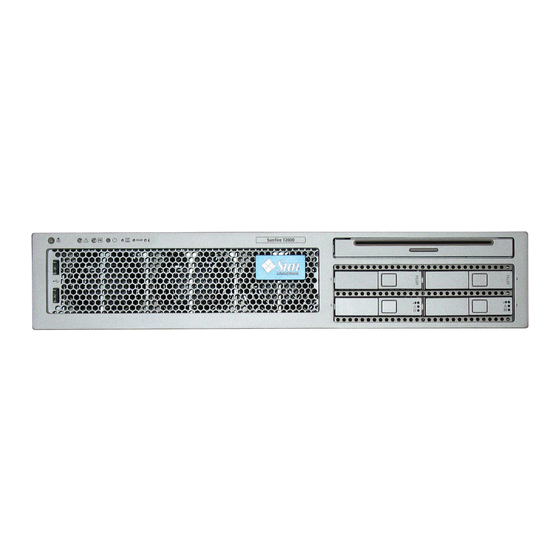
PCI-E slot 0 TTYA serial Indicators GBE ports port USB ports SC serial mgt Power supply 0 Power supply 1 port Netra T2000 Server Rear Panel FIGURE 1-2 Netra T2000 Server FIGURE 1-3 Netra T2000 Server Installation Guide • September 2006... -
Page 19: Server Features
Firmware comprising: • OpenBoot™ PROM for system settings and power-on self test (POST) support • ALOM for remote management Cryptography Hardware-assisted cyptographic acceleration Operating system Solaris 10 3/05 HW2 Operating System preinstalled on disk 0 Chapter 1 Netra T2000 Overview... -
Page 20: Chip-Multitheaded Multicore Processor And Memory Technology
The result is that the 8-core processor handles up to 32 active threads concurrently. Additional processor components, such as L1 cache, L2 cache, memory access crossbar, DDR2 memory controllers, and a JBus I/O interface have been carefully tuned for optimal performance. See FIGURE 1-5 Netra T2000 Server Installation Guide • September 2006... -
Page 21: Performance Enhancements
The server is preinstalled with the Solaris 10 HW 3/05 Operating System (Solaris OS), and offers the following Solaris OS features: Stability, high performance, scalability, and precision of a mature 64-bit operating ■ system Support for over 12,000 leading technical and business applications ■ Chapter 1 Netra T2000 Overview... -
Page 22: Preloaded Java Enterprise System Software
Messaging Server – A high-performance, highly secure messaging platform that ■ provides security features that help ensure the integrity of communications. Portal Server – Provides portal services that identify users through centralized ■ identity services using roles, and policies. Netra T2000 Server Installation Guide • September 2006... -
Page 23: Hardware-Assisted Cryptography
CPU temperature conditions ■ Disk drive status ■ Enclosure thermal conditions ■ Fan speed and status ■ Power supply status ■ Voltage conditions ■ For more information about using ALOM, see the server administration guide. Chapter 1 Netra T2000 Overview... -
Page 24: System Reliability, Availability, And Serviceability
By using the proper software commands, you can install or remove these components while the server is running. Hot-swap technology significantly increases the server’s serviceability and availability by providing the ability to replace hard drives and power supplies without service disruption. Netra T2000 Server Installation Guide • September 2006... -
Page 25: Power Supply Redundancy
PCI fan and three blowers. If the PCI fan or blower fails, the monitoring subsystem detects the failure and generates an error message to the system console, logs the message in the /var/adm/messages file, and lights the Service Required LEDs. Chapter 1 Netra T2000 Overview... -
Page 26: Error Correction And Parity Checking
By automatically diagnosing problems, business-critical applications and essential system services can continue uninterrupted in the event of software failures, or major hardware component failures. Netra T2000 Server Installation Guide • September 2006... -
Page 27: Rackmountable Enclosure
Rackmountable Enclosure The server uses a space-saving 2U-high rackmountable enclosure that can be installed into a variety of industry standard racks. Chapter 1 Netra T2000 Overview... - Page 28 Netra T2000 Server Installation Guide • September 2006...
-
Page 29: Tools Needed
C H A P T E R Preparing for Installation This chapter provides background information about the server installation procedures. This chapter contains these topics: “Tools Needed” on page 13 ■ “Shipping Kit Inventory List” on page 13 ■ “Installation Overview” on page 14 ■... -
Page 30: Installation Overview
Note – In the rest of this manual, the term rack means either an open rack or a closed cabinet. 6. Connect the chassis grounding cable. 7. Connect the serial, network, and all other data cables to the server. See “Cabling the Server” on page Netra T2000 Server Installation Guide • September 2006... - Page 31 8. Connect the server to a serial terminal or a terminal emulator (PC or workstation) to display system messages. See “Powering On the Server for the First Time” on page Tip – The serial terminal or a terminal emulator should be connected, powered on, and ready before you connect the power cables, or you will not see the system messages.
-
Page 32: Installing The Air Filter
2. Carefully remove the shipping insert from the inside of the bezel. 3. Obtain the air filter that shipped with your server. 4. Snap the new air filter into place in the bezel ( FIGURE 2-2 Netra T2000 Server Installation Guide • September 2006... -
Page 33: Installing Optional Components
Installing the Air Filter in the Bezel FIGURE 2-2 5. Close the bezel. Installing Optional Components The standard components of the server are installed at the factory. However, if you ordered options such as additional memory or a PCI card, these will be shipped separately. -
Page 34: Slide Rail Assembly Notes
Each slide rail assembly consists of a three-section slide rail and a removable mounting bracket ( FIGURE 2-3 Mounting bracket Rear section Middle section Front section Sections of the Slide Rail Assembly FIGURE 2-3 Netra T2000 Server Installation Guide • September 2006... -
Page 35: Figure 2-4 Locating The Locks On The Slide Rail Assembly
The front, middle, and rear sections form the slide rail. The middle and rear sections ■ have holes for mounting screws and adjust to fit rack depths from 24 in. (61 cm) to 36.5 in. (93 cm). The front section can be extended to enable movement of the server out of the rack. -
Page 36: Safety Precautions
Caution – When completing a two-person procedure, always communicate your intentions clearly before, during, and after each step to minimize confusion. Netra T2000 Server Installation Guide • September 2006... - Page 37 C H A P T E R Mounting the Server Into a 4-Post Rack This chapter provides instructions for installing the server in an open 4-post rack or closed cabinet. This chapter contains the following sections: “4-Post Rackmounting Options” on page 22 ■...
-
Page 38: 4-Post Rackmounting Options
▼ Post Rack The hardmount kit for a 19-inch 4-post rack consists of: Two hardmount brackets ■ Two rear mount support brackets ■ Two rear mount flanges ■ Bag of screws ■ Netra T2000 Server Installation Guide • September 2006... -
Page 39: Figure 3-1 Contents Of The Hardmount 19-Inch 4-Post Kit
Note – The front-to-back rail spacing must be at least 460 mm (18.11 in.) and not more than 715 mm (28.15 in.) from the outside face of the front rail to the outside face of the back rail. Rear mount support brackets Screws Hardmount brackets Rear mount... -
Page 40: Figure 3-2 Securing The Hardmount Brackets To The Server
( FIGURE 3-3 Use two to three of the supplied M4 × 0.5 × 5 mm panhead Phillips screws for each bracket, depending on the rack depth. Netra T2000 Server Installation Guide • September 2006... -
Page 41: Figure 3-3 Attaching The Rear Mount Support Brackets
Attaching the Rear Mount Support Brackets FIGURE 3-3 6. Lift the server to the desired location in the rack. 7. Using two screws per side, secure the front of the hardmount brackets attached to the sides of the server to the front of the rack ( FIGURE 3-4 Securing the Front of the Server to the Rack FIGURE 3-4... -
Page 42: Mounting The Server In A Sliding Rail Mount 19-Inch 4-Post Rack
863.6 mm (34 in.) from the outside face of the front rail to the outside face of the back rail. You also need the hardmount brackets from the standard rackmount kit that came with the server ( FIGURE 3-1 Netra T2000 Server Installation Guide • September 2006... -
Page 43: Figure 3-6 Contents Of The Sliding Rail 19-Inch 4-Post Kit
Telco slide Screws assemblies Threaded strips Short brackets Extension brackets Long brackets Contents of the Sliding Rail 19-Inch 4-Post Kit FIGURE 3-6 Sliding Rail 19-inch 4-Post Rackmount Screw Kit Contents TABLE 3-3 Number Description Where Used M4 x 0.5 mm x 5 mm Phillips panhead screws 8 for glides, 2 extra M6 brass collar screws 4 for short brackets, 4 for long brackets, 2 extra... -
Page 44: Figure 3-7 Securing The Hardmount Bracket To The Server
3. Get the Telco slide assemblies from the rack kit ( FIGURE 3-6 4. Press in the button on each slide and pull the glide completely out of the slide FIGURE 3-8 Netra T2000 Server Installation Guide • September 2006... -
Page 45: Figure 3-8 Dismantling The Slide
Button Slide (in two parts) Glide Dismantling the Slide FIGURE 3-8 5. Using eight of the M4 × 0.5 × 5 mm panhead Phillips screws from the rackmount kit (four for each side), screw each glide to the side of the server chassis FIGURE 3-9 Fixing the Glides to the Server Chassis FIGURE 3-9... -
Page 46: Figure 3-10 Securing The Brackets To The Rack
Use the M5 panhead screws from the inside, and the M5 nuts, plain washers, and star washers from the outside. Use extension brackets instead of the long brackets if the dimension is greater than 665 mm Netra T2000 Server Installation Guide • September 2006... -
Page 47: Figure 3-11 Securing The Slide To The Brackets
Long bracket Slide Short bracket Securing the Slide to the Brackets FIGURE 3-11 11. Repeat Step 9 Step 10 for the slide on the other side of the rack. 12. Push the slides completely into the assembly on each side of the rack and release the stop catches. -
Page 48: Figure 3-12 Sliding The Server Into The Rack
( FIGURE 3-13 The size of the screws varies, depending on your particular rack. Securing the Front of the Server to the Rack FIGURE 3-13 Netra T2000 Server Installation Guide • September 2006... -
Page 49: Hardmounting The Server In A 600-Mm 4-Post Rack
Hardmounting the Server in a 600-mm 4- Post Rack ▼ To Install a Server With a Hardmount in a 600- mm 4-Post Rack The hardmount kit for a 600 mm 4-post rack consists of: Two adjustable rails ■ Two side rails ■... -
Page 50: Figure 3-14 Contents Of The Hardmount 600-Mm 4-Post Kit
1. Get the adjustable rails from the rack kit ( FIGURE 3-14 2. Loosen the two screws at the middle of each adjustable rail so that you can extend the adjustable rail ( FIGURE 3-15 Netra T2000 Server Installation Guide • September 2006... -
Page 51: Figure 3-15 Adjustable Rail Screws
Adjustable rail screws Adjustable Rail Screws FIGURE 3-15 3. Lift one of the adjustable rails to the desired location in the rack. Using two screws, secure the front of the rail in the rack ( FIGURE 3-16 Chapter 3 Mounting the Server Into a 4-Post Rack... -
Page 52: Figure 3-16 Securing The Front Of The Adjustable Rails To The Rack
4. At the rear of the rack, use two screws to secure the rear of the adjustable rails to the rack ( FIGURE 3-17 The size of the screws varies, depending on your particular rack. Netra T2000 Server Installation Guide • September 2006... -
Page 53: Figure 3-17 Securing The Rear Of The Adjustable Rails To The Rack
Securing the Rear of the Adjustable Rails to the Rack FIGURE 3-17 5. Tighten the two screws at the middle of each adjustable rail ( FIGURE 3-15 Step 3 Step 5 6. Repeat through to mount the other adjustable rail into the rack. 7. -
Page 54: Figure 3-18 Installing The Rear Flange Onto The Adjustable Rail
The side rails can accommodate rack rail setbacks (the distance from the front of the rack to the rack rail) of 50 mm, 75 mm, or 100 mm, depending on the type of rack you are installing the server into. Netra T2000 Server Installation Guide • September 2006... -
Page 55: Figure 3-19 Securing The Side Rails To The Server
Securing the Side Rails to the Server FIGURE 3-19 11. Lift the server into the rack and slide the server onto the adjustable rails FIGURE 3-20 Sliding the Server Onto the Adjustable Rails FIGURE 3-20 12. Push the server to the desired depth in the rack, then go to the rear of the server and push the rear flanges flush against the back of the server ( FIGURE 3-18 If the rack is especially shallow, you can flip the rear flanges around so that they rest... -
Page 56: Figure 3-21 Securing The Rear Of The Server To The Rear Flanges
17. At the front of the rack, use two screws per side to secure the side rails that are attached to the server to the front of the rack ( FIGURE 3-22 The size of the screws varies, depending on your particular rack. Netra T2000 Server Installation Guide • September 2006... -
Page 57: Installing A Server With A Hardmount In A 19-Inch 4-Post Rack For Use With The Cable Management Assembly
See “Shipping Kit Inventory List” on page 13 and the Netra T2000 Server Getting Started Guide, 819-5844. This document is shipped with the server. The rackmount kit contains two slide rail assemblies. A slide rail assembly can be installed on either the right or left side of the rack. -
Page 58: To Install The Slide Rail Assemblies
Pull the mounting bracket out until it locks in the extended position. c. Slide the mounting bracket release button in the direction shown in FIGURE 3-24 then slide the mounting bracket out of the slide rail. Netra T2000 Server Installation Guide • September 2006... -
Page 59: Figure 3-24 Location Of The Mounting Bracket Release Button
Location of the Mounting Bracket Release Button FIGURE 3-24 d. Press the metal lever (labeled Push) on the middle section ( ) of the FIGURE 3-25 sliding rail, then push the middle section back into the rack. Metal lever Unlocking the Slide Rail Middle Section FIGURE 3-25 2. -
Page 60: Figure 3-26 Attaching A Mounting Bracket To The Chassis
The server is two rack units tall (2 RU). The slide rails occupy the lower half of the 2 RU space. 5. Determine which screws you will use to mount the slide rails. Netra T2000 Server Installation Guide • September 2006... -
Page 61: Figure 3-27 Mounting A Slide Rail
If your rack has threaded mounting holes in the rack posts, determine whether ■ the threads are metric or standard. Select the appropriate screws from the package included in the mounting kit. If your rack does not have threaded mounting holes, the mounting screws are ■... -
Page 62: Figure 3-28 Adjusting The Distance Between The Slide Rails
Caution – The server weighs approximately 40 lb (18 kg). Two people are required to lift and mount the server into a rack enclosure when using the procedures in this chapter. Netra T2000 Server Installation Guide • September 2006... -
Page 63: To Install The Cable Management Assembly
10. Insert the ends of the mounting brackets into the sliding rails ( FIGURE 3-29 Mounting the Chassis on the Slide Rails FIGURE 3-29 11. Slide the chassis into the rack. Caution – Verify that the server is securely mounted in the rack, and that the slide rails are locked to the mounting brackets, before continuing. -
Page 64: Figure 3-30 Inserting The Cma Rail Extension Into The Rear Of The Left Slide Rail
Inserting the CMA Rail Extension Into the Rear of the Left Slide Rail FIGURE 3-30 2. Insert the smaller CMA extension into the clip located at the end of the mounting bracket ( FIGURE 3-31 Netra T2000 Server Installation Guide • September 2006... -
Page 65: Figure 3-31 Mounting The Inner Cma Connector
Mounting the Inner CMA Connector FIGURE 3-31 3. Insert the larger extension into the end of the right rail ( FIGURE 3-32 Attaching the Outer CMA Connector FIGURE 3-32 Chapter 3 Mounting the Server Into a 4-Post Rack... -
Page 66: To Verify The Operation Of The Slide Rails And The Cma
Tip – Two people are needed for this procedure, one to move the server in and out of the rack, and one to observe the cables and CMA. Netra T2000 Server Installation Guide • September 2006... -
Page 67: Figure 3-34 Unlocking The Slide Rail Assembly
1. For a cabinet or a free-standing rack, deploy the antitilt bar. 2. Unlock the slide lock buttons ( ) at the right and lefts sides of the server FIGURE 3-34 chassis, and slowly pull the server out of the rack until the slide rails reach their stops. -
Page 68: Figure 3-35 Unlocking The Slide Rail Lever Stops
Slide Rail Release Button FIGURE 3-36 The server should stop after approximately 15 in. (40 cm) of travel. 8. Verify that the cables and the CMA retracted without binding. Netra T2000 Server Installation Guide • September 2006... - Page 69 9. Adjust the cable hangers and CMA as required. Chapter 3 Mounting the Server Into a 4-Post Rack...
- Page 70 Netra T2000 Server Installation Guide • September 2006...
- Page 71 C H A P T E R Mounting the Server Into a 2-Post Rack This chapter provides instructions for installing the server in an open 2-post rack. This chapter contains the following sections: “2-Post Rackmounting Options” on page 56 ■ “Hardmounting the Server in a 23-Inch 2-Post Rack”...
-
Page 72: 2-Post Rackmounting Options
■ Note – The 23-inch 2-post rackmount kit supports rack web thicknesses (the width of the rack post) of 76.20 mm (3 in.), 101.6 mm (4 in.), and 127 mm (5 in.). Netra T2000 Server Installation Guide • September 2006... -
Page 73: Figure 4-1 Contents Of The Hardmount 23-Inch 2-Post Kit
Rear plates Rail guides Screws Side brackets Contents of the Hardmount 23-Inch 2-Post Kit FIGURE 4-1 Hardmount 23-Inch 2-Post Rackmount Screw Kit Contents TABLE 4-2 Number Description Where Used M5 x 10 SEM screws 8 for side brackets, 2 for rear plates M5 x 12.7 mm screws 10 for rack, if appropriate M6 x 13 mm screws... -
Page 74: Figure 4-2 Securing The Side Brackets To The Side Of The Server
4. Lift the rail guides to the desired height in the rack and, using two screws each, secure both rail guides to the rack ( FIGURE 4-3 The size of the screws varies, depending on your particular rack. Installing the Rail Guides in the Rack FIGURE 4-3 Netra T2000 Server Installation Guide • September 2006... -
Page 75: Figure 4-4 Installing And Securing The Server In The 2-Post Rack
5. Lift the server into the rack and slide the server onto the rail guides ( FIGURE 4-4 Installing and Securing the Server in the 2-Post Rack FIGURE 4-4 6. Using two screws on each side, secure each side bracket on the server to the front of the rack ( FIGURE 4-4 The size of the screws varies, depending on your particular rack. -
Page 76: Figure 4-5 Installing A Screw On The Middle Rack Position On The Rear Plate
The screw head should be facing the rear of the server and the other side of the rear plate should be in front of the rack post ( FIGURE 4-6 Installing the Rear Plate to the Side Bracket FIGURE 4-6 Netra T2000 Server Installation Guide • September 2006... -
Page 77: Hardmounting The Server In A 19-Inch 2-Post Rack
c. Tighten the screw to secure the rear plate to the eyelet on the side bracket FIGURE 4-6 d. Using two screws, secure the other side of the rear plate to the back of the post FIGURE 4-7 Securing the Rear Plate to the Back of the Post FIGURE 4-7 The size of the screws varies, depending on your rack. -
Page 78: Figure 4-8 Contents Of The Hardmount 19-Inch 2-Post Kit
1. Get the side brackets from the rack kit ( FIGURE 4-8 2. Using four of the M5 × 10 SEM screws for each side bracket, secure the side brackets to the sides of the server ( FIGURE 4-9 Netra T2000 Server Installation Guide • September 2006... -
Page 79: Figure 4-9 Securing The Side Brackets To The Side Of The Server
Securing the Side Brackets to the Side of the Server FIGURE 4-9 3. Lift the server into the rack. 4. Using two screws for each bracket, secure the front of the server to the front of the rack ( FIGURE 4-10 Installing and Securing the Server in the 2-Post Rack FIGURE 4-10 Chapter 4 Mounting the Server Into a 2-Post Rack... -
Page 80: Figure 4-11 Installing Screws On The Optimum Rack Position On The Rear Plate
Slide the rear plate in so that the screws slide into position into one set of the eyelets. The screw heads should be facing the rear of the server and the other side of the rear plate should be in front of the rack post ( FIGURE 4-12 Netra T2000 Server Installation Guide • September 2006... -
Page 81: Figure 4-12 Installing The Rear Plate To The Side Bracket
Installing the Rear Plate to the Side Bracket FIGURE 4-12 c. Tighten the screws to secure the rear plate to the set of eyelets on the side bracket ( FIGURE 4-12 d. Using two screws, secure the other side of the rear plate to the back of the post FIGURE 4-13 Chapter 4 Mounting the Server Into a 2-Post Rack... -
Page 82: Figure 4-13 Securing The Rear Plate To The Rack
Securing the Rear Plate to the Rack FIGURE 4-13 The size of the screws varies, depending on your rack. Step a Step d e. Repeat through to secure the rear plate on the other post. Netra T2000 Server Installation Guide • September 2006... -
Page 83: Data Ports And Cabling Notes
C H A P T E R Cabling the Server This chapter provides instructions for cabling the server. Topics include: “Data Ports and Cabling Notes” on page 67 ■ “Connecting Cables” on page 69 ■ “Managing Cables With the CMA” on page 75 ■... -
Page 84: Cabling Notes
ALOM system controller. The SC serial management port (labeled SERIAL MGT) uses an RJ-45 cable and ■ is always available. This is the default connection to the ALOM system controller. Netra T2000 Server Installation Guide • September 2006... -
Page 85: Connecting Cables
The SC network management port (labeled NET MGT) is the optional ■ connection to the ALOM system controller. This port is not available until you have configured network settings for the system controller (through the SC serial management port). See “Enabling the System Controller Network Management Port”... -
Page 86: To Connect The Sc Serial Management Port
“Enabling the System Controller Network Management Port” on page The SC serial management port is marked SER MGT. It is the leftmost RJ-45 port on the rear of the chassis ( FIGURE 5-3 Netra T2000 Server Installation Guide • September 2006... -
Page 87: To Connect The Sc Network Management Port
SER MGT System Controller Serial Connection FIGURE 5-3 ● Connect a Category 5 cable from the SC serial management port to the terminal device. ▼ To Connect the SC Network Management Port The SC network management port is marked NET MGT. It is the RJ-45 port above the rear USB ports. -
Page 88: Input Power Cables
The TTYA serial port connector uses a DB-9 connector (item 1 in ). Use this FIGURE 5-5 port for general-purpose serial data transfers. This port is not connected to the SC serial management port. Netra T2000 Server Installation Guide • September 2006... -
Page 89: Usb Ports
Serial port (TTYA) Serial Port FIGURE 5-5 Use a null modem cable or an adapter to perform the crossovers given for each connector. If connecting to a serial port on a personal computer, use Sun adapter part ■ number 530-3100-01. If connecting to a Sun workstation or server, use Sun adapter part number 530- ■... -
Page 90: Alarm Port
USB ports USB Ports FIGURE 5-6 Alarm Port The server has a dry-contact alarm port to support telco applications. Alarm port Alarm Port FIGURE 5-7 Netra T2000 Server Installation Guide • September 2006... -
Page 91: Managing Cables With The Cma
Managing Cables With the CMA ▼ To Open and Close a Cable Clip 1. To open a cable clip, press the front of the cable clip and lift the hinged top. 2. Route cables through the clip, then press the top of the cable clip to lock. Opening a Cable Clip FIGURE 5-8 Chapter 5 Cabling the Server... -
Page 92: Figure 5-9 Removing A Cable Clip
2. To insert a cable clip, position the upper and lower clip locks in the slots of the CMA arm, then press the clip down approximately 3/8 in. (10 mm). Mounting or Moving a Cable Clip FIGURE 5-10 Netra T2000 Server Installation Guide • September 2006... -
Page 93: Powering On The Server For The First Time
C H A P T E R Powering On the Server This chapter includes instructions for booting the server and for enabling the system controller network management port. The following topics are discussed: “Powering On the Server for the First Time” on page 77 ■... -
Page 94: Figure 6-1 Rear Panel Power Connectors
The following example shows partial output from the system controller boot sequence leading to the login prompt. Sample System Controller Output CODE EXAMPLE 6-1 ALOM POST 1.0 Dual Port Memory Test, PASSED. Netra T2000 Server Installation Guide • September 2006... - Page 95 Sample System Controller Output (Continued) CODE EXAMPLE 6-1 TTY External - Internal Loopback Test TTY External - Internal Loopback Test, PASSED. TTYC - Internal Loopback Test TTYC - Internal Loopback Test, PASSED. TTYD - Internal Loopback Test TTYD - Internal Loopback Test, PASSED.....
-
Page 96: Enabling The System Controller Network Management Port
Network Management Port” on page To Log Into the System Controller Using the ▼ Serial Management Port After the system controller boots, you can access the ALOM command-line interface to configure and manage the server. Netra T2000 Server Installation Guide • September 2006... -
Page 97: To Configure The System Controller Network Management Port
The sc prompt is displayed the first time the system controller is booted. The default configuration provides an ALOM user account called admin. There is no default password, so you must create a password using the system controller (sc) password command. 1. - Page 98 5. Use the showsc command to verify that the parameters were set correctly. The showsc command displays all the configuration parameters and their values, as listed in TABLE 6-1 Netra T2000 Server Installation Guide • September 2006...
-
Page 99: Table 6-1 Sample Configuration Parameter Setting
Note – The highlighted parameters must be set according to the specific details of your network configuration for the network management port to function properly. Sample Configuration Parameter Setting TABLE 6-1 Parameter Sample Value netsc_enetaddr 00:03:ba_81:2d_02 if_network true if_modem false if_emailalerts false sys_autorestart... -
Page 100: To Reset The System Controller
TTY External - Internal Loopback Test TTY External - Internal Loopback Test, PASSED. TTYC - Internal Loopback Test TTYC - Internal Loopback Test, PASSED. TTYD - Internal Loopback Test TTYD - Internal Loopback Test, PASSED. Netra T2000 Server Installation Guide • September 2006... -
Page 101: To Log Into The System Controller Using The Network Management Port
....Full VxDiag Tests - PASSED Status summary Status = 7FFF VxDiag PASSED POST PASSED LOOPBACK PASSED PASSED EPROM PASSED FRU PROM PASSED ETHERNET PASSED MAIN CRC PASSED BOOT CRC PASSED TTYD PASSED TTYC PASSED MEMORY PASSED MPC885 PASSED Please login: To Log Into the System Controller Using the ▼... -
Page 102: Using The System Controller For Common Operations
To initiate the power-on sequence, issue the poweron command. You see an sc> alert message on the system console. This message indicates that the server has reset. sc> poweron SC Alert: Host System has Reset sc> Netra T2000 Server Installation Guide • September 2006... -
Page 103: To Connect To The System Console
To Connect to the System Console ▼ Output from POST, OpenBoot, and the Solaris OS is displayed in the system console using the network console on the system controller. ● Execute the console command, and use the –f option to force the console to be attached to your session. -
Page 104: Table 6-2 Map Of Devices, Openboot Path Names, And Locations
IOBD/PCI-BRIDGE /pci@7c0/pci@0/pci@2 PCI-X Slot 0 (J3201) PCIX0 /pci@7c0/pci@0/pci@2/pci@0 PCI-X Slot 1 (J3301) PCIX1 /pci@7c0/pci@0/pci@2/pci@0 ULI Southbridge Chip (U3702) IOBD/PCIX-IO /pci@7c0/pci@0/pci@2/pci@0,2 PCI-E Slot 2 (J2202) PCIE2 /pci@7c0/pci@0/pci@8 PCI-E Slot 1 (J2201) PCIE1 /pci@7c0/pci@0/pci@9 Netra T2000 Server Installation Guide • September 2006... -
Page 105: Booting The Solaris Operating System
Loading ufs-file-system package 1.4 04 Aug 1995 13:02:54. FCode UFS Reader 1.12 00/07/17 15:48:16. Loading: /platform/SUNW,Ontario/ufsboot Loading: /platform/sun4v/ufsboot SunOS Release 5.10 Version /net/spa/export/spa2/ws/pothier/grlks10-ontario:12/01/2004 64-bit Copyright 1983-2004 Sun Microsystems, Inc. All rights reserved. Use is subject to license terms. Chapter 6 Powering On the Server... -
Page 106: To Reset The Server
To Power Cycle the Server If a simple reset does not clear a server problem, you can power the server off and on with this procedure. 1. Shut down the Solaris OS. Netra T2000 Server Installation Guide • September 2006... - Page 107 At the Solaris OS prompt, issue the uadmin command to halt the Solaris OS and to return to the ok prompt. # uadmin 2 0 WARNING: proc_exit: init exited syncing file systems... done Program terminated 2. Switch from the system console prompt to the SC console prompt by issuing the #.
- Page 108 Netra T2000 Server Installation Guide • September 2006...
-
Page 109: Table A-1 Server Software Configuration Worksheet
A P P E N D I X Software Configuration Worksheet Use the following worksheet to gather the information that you need to configure software on the server. You do not need to gather all of the information that is requested on the worksheet. - Page 110 Internet? server (Only available in If you use a proxy server, provide the following the Solaris Web information: Start program) Host: Port: Netra T2000 Server Installation Guide • September 2006...
- Page 111 Server Software Configuration Worksheet (Continued) TABLE A-1 Information Needed to Install Description/Example Your Answers Automatic Reboot Reboot automatically after software installation? Yes/No or CD/DVD Eject CD/DVD automatically after software installation? Yes/No Ejection Software Group Which Solaris group do you want to install? Entire plus OEM Entire Developer...
- Page 112 Netra T2000 Server Installation Guide • September 2006...
- Page 113 Index Numerics connecting Ethernet, 69 19-inch 2-post hardmount network management, 71 installing, 61 serial management, 70 screw kit, 62 managing, 75 19-inch 4-post hardmount power, 72 installing, 22 cabling notes, 68 screw kit, 23 cryptography, 7 19-inch 4-post slide mount installing, 26 screw kit, 27 data ports, 67...
- Page 114 84 rackmounting 2-post, 55 hardmount 19-inch, 61 temperature sensors, 9 hardmount 23-inch, 56 thermistors, 9 4-post, 21 cable management assembly, 41 hardmount 19-inch, 22 UltraSPARC T1, 4 hardmount 600mm, 33 Netra T2000 Server Installation Guide • September 2006...
- Page 115 USB ports, 73 Index...
- Page 116 Netra T2000 Server Installation Guide • September 2006...
Need help?
Do you have a question about the Netra T2000 and is the answer not in the manual?
Questions and answers