
Related Manuals for Sun Microsystems Sun Fire T2000


Summary of Contents for Sun Microsystems Sun Fire T2000
-
Page 1: Service Manual
Sun Fire T2000 Server ™ Service Manual Sun Microsystems, Inc. www.sun.com Part No. 819-2548-14 July 2007, Revision A Submit comments about this document at: http://www.sun.com/hwdocs/feedback... - Page 2 Fujitsu Limited or Sun Microsystems, Inc., or any affiliate of either of them.
- Page 3 Aucune partie de ce produit, de ces technologies ou de ce document ne peut être reproduite sous quelque forme que ce soit, par quelque moyen que ce soit, sans l’autorisation écrite préalable de Fujitsu Limited et de Sun Microsystems, Inc., et de leurs éventuels bailleurs de licence.
-
Page 5: Table Of Contents
Contents Preface xvii Safety Information 1–1 Safety Information 1–1 Safety Symbols 1–1 Electrostatic Discharge Safety 1–2 1.3.1 Using an Antistatic Wrist Strap 1–2 1.3.2 Using an Antistatic Mat 1–2 Server Overview 2–1 Server Features 2–2 2.1.1 Chip Multitheaded Multicore Processor and Memory Technology 2–2 2.1.2 Performance Enhancements 2–4... - Page 6 Running the showfaults Command 3–21 3.3.3 Running the showenvironment Command 3–22 3.3.4 Running the showfru Command 3–25 Running POST 3–26 3.4.1 Controlling How POST Runs 3–26 3.4.2 Changing POST Parameters 3–30 Sun Fire T2000 Server Service Manual • July 2007...
- Page 7 3.4.3 Reasons to Run POST 3–31 3.4.3.1 Verifying Hardware Functionality 3–31 3.4.3.2 Diagnosing the System Hardware 3–32 3.4.4 Running POST in Maximum Mode 3–32 3.4.5 Correctable Errors Detected by POST 3–36 3.4.5.1 Correctable Errors for Single DIMMs 3–37 3.4.5.2 Determining When to Replace Detected Devices 3–38 3.4.6 Clearing POST Detected Faults 3–39 Using the Solaris Predictive Self-Healing Feature 3–40...
- Page 8 Replacing PCI Cards 5–11 5.2.3 Removing DIMMs 5–12 5.2.4 Replacing DIMMs 5–14 5.2.5 Removing the System Controller Card 5–17 5.2.6 Replacing the System Controller Card 5–18 5.2.7 Removing the Motherboard Assembly 5–19 viii Sun Fire T2000 Server Service Manual • July 2007...
- Page 9 5.2.8 Replacing the Motherboard Assembly 5–23 5.2.9 Removing the Power Distribution Board 5–27 5.2.10 Replacing the Power Distribution Board 5–30 5.2.11 Removing the LED Board 5–32 5.2.12 Replacing the LED Board 5–33 5.2.13 Removing the Fan Power Board 5–34 5.2.14 Replacing the Fan Power Board 5–34 5.2.15 Removing the Front I/O Board 5–35 5.2.16 Replacing the Front I/O Board 5–36 5.2.17 Removing the DVD Drive 5–37...
- Page 10 6.2.3 PCI Express or PCI-X Card Guidelines 6–7 6.2.4 Adding a PCI-Express or PCI-X Card 6–7 A. Field-Replaceable Units A–1 Illustrated FRU Locations A–2 Index Index–1 Sun Fire T2000 Server Service Manual • July 2007...
- Page 11 Figures Server 2–2 FIGURE 2-1 Motherboard and UltraSPARC T1 Multicore Processor 2–3 FIGURE 2-2 Server Front Panel 2–9 FIGURE 2-3 Server Rear Panel 2–9 FIGURE 2-4 Diagnostic Flow Chart 3–3 FIGURE 3-1 Front Panel LEDs 3–9 FIGURE 3-2 Rear Panel LEDs 3–9 FIGURE 3-3 Hard Drive LEDs 3–11 FIGURE 3-4...
- Page 12 Removing the Front I/O Board 5–36 FIGURE 5-24 Removing the SAS Disk Backplane 5–38 FIGURE 5-25 Replacing the SAS Disk Backplane 5–39 FIGURE 5-26 Removing the Battery From the System Controller 5–40 FIGURE 5-27 Sun Fire T2000 Server Service Manual • July 2007...
- Page 13 Replacing the Battery in the System Controller 5–40 FIGURE 5-28 Replacing the Top Front Cover 5–41 FIGURE 5-29 Returning the Server to the Rack 5–43 FIGURE 5-30 Release Levers 5–44 FIGURE 5-31 Installing the CMA 5–45 FIGURE 5-32 Hard Drive Slots 6–3 FIGURE 6-1 Adding a USB Device 6–4 FIGURE 6-2...
- Page 14 Sun Fire T2000 Server Service Manual • July 2007...
- Page 15 Tables Server Features 2–4 TABLE 2-1 Diagnostic Flowchart Actions 3–4 TABLE 3-1 Front and Rear Panel LEDs 3–10 TABLE 3-2 Hard Drive LEDs 3–11 TABLE 3-3 Power Supply LEDs 3–12 TABLE 3-4 Fan LEDs 3–13 TABLE 3-5 Blower Unit LED 3–14 TABLE 3-6 Ethernet Port LEDs 3–15 TABLE 3-7...
- Page 16 Sun Fire T2000 Server Service Manual • July 2007...
-
Page 17: Preface
Preface The Sun Fire T2000 Server Service Manual provides information to aid in diagnosing hardware problems and describes how to replace components within the Sun Fire™ T2000 server. This guide also describes how to add components such as hard drives and memory to the server. -
Page 18: Additional Service Related Information
In addition to this service manual, the following resources are available to help you keep your server running optimally: Product Notes – The Sun Fire T2000 Server Product Notes (819-2544) contain late- ■ breaking information about the system including required software patches, updated hardware and compatibility information, and solutions to know issues. -
Page 19: Typographic Conventions
Release Notes – The Solaris OS release notes contain important information about ■ the Solaris OS. The release notes are available online at: http://www.sun.com/documentation SunSolve Online – Provides a collection of support resources. Depending on ■ the level of your service contract, you have access to Sun patches, the Sun System Handbook, the SunSolve™... - Page 20 Documentation, Support, and Training Sun Function Documentation http://www.sun.com/documentation/ Support http://www.sun.com/support/ Training http://www.sun.com/training/ xx Sun Fire T2000 Server Service Manual • July 2007...
-
Page 21: Sun Welcomes Your Comments
Sun is interested in improving its documentation and welcomes your comments and suggestions. You can submit your comments by going to: http://www.sun.com/hwdocs/feedback Please include the title and part number of your document with your feedback: Sun Fire T2000 Server Service Manual, part number 819-2548-14 Preface... - Page 22 Sun Fire T2000 Server Service Manual • July 2007...
-
Page 23: Safety Information
C H A P T E R Safety Information This chapter provides important safety information for servicing the server. The following topics are covered: Section 1.1, “Safety Information” on page 1-1 ■ Section 1.2, “Safety Symbols” on page 1-1 ■ Section 1.3, “Electrostatic Discharge Safety”... -
Page 24: Electrostatic Discharge Safety
1.3.2 Using an Antistatic Mat Place ESD-sensitive components such as the motherboard, memory, and other PCB cards on an antistatic mat. Sun Fire T2000 Server Service Manual • July 2007... -
Page 25: Server Overview
C H A P T E R Server Overview This chapter provides an overview of the features of the server. The following topics are covered: Section 2.1, “Server Features” on page 2-2 ■ Section 2.2, “Chassis Identification” on page 2-9 ■... -
Page 26: Server Features
Depending on the model purchased, the processor has four, six, or eight UltraSPARC cores. Each core equates to a 64-bit execution pipeline capable of running four threads. The result is that the 8-core processor handles up to 32 active threads concurrently. Sun Fire T2000 Server Service Manual • July 2007... -
Page 27: Figure 2-2 Motherboard And Ultrasparc T1 Multicore Processor
Additional processor components, such as L1 cache, L2 cache, memory access crossbar, DDR2 memory controllers, and a JBus I/O interface have been carefully tuned for optimal performance. UltraSPARC T1 multicore processor Motherboard and UltraSPARC T1 Multicore Processor FIGURE 2-2 Chapter 2 Server Overview... -
Page 28: Performance Enhancements
Other internal 1 slimline DVD-R/CD-RW device peripherals USB ports 4 USB 1.1 ports (2 in front and 2 in rear) Cooling 3 hot-swappable and redundant system fans and 1 blower unit Sun Fire T2000 Server Service Manual • July 2007... -
Page 29: Remote Manageability With Alom Cmt
• 3.3v (5v is also supplied, as defined by the PCI-X specification, using a 3.3V form factor connector) Power 2 hot-swappable and redundant power supply units (PSUs) Sun Fire T2000 Refer to the Server Site Planning Guide for power and environmental specifications. -
Page 30: System Reliability, Availability, And Serviceability
Environmental monitoring ■ Error detection and correction for improved data integrity ■ Easy access for most component replacements ■ Extensive POST tests that automatically delete faulty components from the ■ configuration Sun Fire T2000 Server Service Manual • July 2007... -
Page 31: Hot-Pluggable And Hot-Swappable Components
PSH automated run-time diagnosis capability that takes faulty components ■ offline. For more information about using RAS features, refer to the Sun Fire T2000 Server Administration Guide. 2.1.4.1 Hot-Pluggable and Hot-Swappable Components The server hardware supports hot-plugging or hot-swapping of the chassis-mounted hard drives, fans, power supplies, and the rear blower. -
Page 32: Error Correction And Parity Checking
By automatically diagnosing problems, business-critical applications and essential system services can continue uninterrupted in the event of software failures, or major hardware component failures. Sun Fire T2000 Server Service Manual • July 2007... -
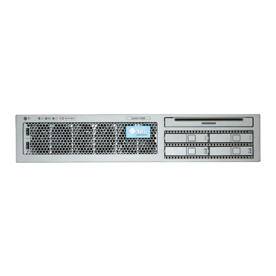
Page 33: Chassis Identification
Chassis Identification show the physical characteristics of the server. FIGURE 2-3 FIGURE 2-4 Indicators and buttons DVD drive HDD 2 HDD 3 HDD 0 HDD 1 USB ports Hard drives Server Front Panel FIGURE 2-3 SC serial mgt GBE ports port TTYA serial SC net mgt... -
Page 34: Obtaining The Chassis Serial Number
You can also run the ALOM CMT showplatform command to obtain the chassis serial number. Example: sc> showplatform SUNW,Sun-Fire-T2000 Chassis Serial Number: 0529AP000882 Domain Status ------ ------ S0 OS Standby sc> 2-10 Sun Fire T2000 Server Service Manual • July 2007... -
Page 35: Server Diagnostics
C H A P T E R Server Diagnostics This chapter describes the diagnostics that are available for monitoring and troubleshooting the server. This chapter is intended for technicians, service personnel, and system administrators who service and repair computer systems. The following topics are covered: Section 3.1, “Overview of Server Diagnostics”... -
Page 36: Table
The flow chart assumes that you have already performed some troubleshooting such as verification of proper installation, and visual inspection of cables and power, and possibly performed a reset of the server (refer to the Sun Fire T2000 Server Installation Guide and Sun Fire T2000 Server Administration Guide for details). -
Page 37: Figure 3-1 Diagnostic Flow Chart
flowchart Numbers in this flow chart Check the 1. Are the correspond to the Action Faulty power source Power OK and numbers in Table 2-1. hardware AC OK LEDs suspected connections. off? 2. Are any faults reported showfaults by the ALOM command showfaults displays a... -
Page 38: Table 3-1 Diagnostic Flowchart Actions
Solaris OS. on page 3-49 • If SunVTS reports a faulty device replace the FRU. Chapter 5 • If SunVTS does not report a faulty device, go to Action No. Sun Fire T2000 Server Service Manual • July 2007... - Page 39 Diagnostic Flowchart Actions (Continued) TABLE 3-1 Action For more information, see Diagnostic Action Resulting Action these sections Run POST. POST performs basic tests of the server components Section 3.4, “Running and reports faulty FRUs. POST” on page 3-26 Note - diag_level=min is the default ALOM CMT setting, which tests devices required to boot TABLE 3-9 TABLE 3-10...
-
Page 40: Memory Configuration And Fault Handling
DIMM sizes: 512 MB (maximum of 8 GB) ■ 1 GB (maximum of 16 GB) ■ 2 GB (maximum of 32 GB) ■ 4 GB (maximum of 64 GB) ■ Sun Fire T2000 Server Service Manual • July 2007... -
Page 41: Memory Fault Handling
DIMMs are installed in groups of eight, called ranks (ranks 0 and 1). At a minimum, rank 0 must be fully populated with eight DIMMS of the same capacity. A second rank of DIMMs of the same capacity, can be added to fill rank 1. Section 5.2.3, “Removing DIMMs”... -
Page 42: Troubleshooting Memory Faults
The six front panel LEDs ( ) are located in the upper left corner of the FIGURE 3-2 server chassis. Three of these LEDs are also provided on the rear panel ( FIGURE 3-3 Sun Fire T2000 Server Service Manual • July 2007... -
Page 43: Figure 3-2 Front Panel Leds
Service Power Required On/Off Rear-FRU Fault button Power OK Locator Top Fan Over Temp LED/button Front Panel LEDs FIGURE 3-2 Locator Service Power OK Required LED/button Rear Panel LEDs FIGURE 3-3 Chapter 3 Server Diagnostics... -
Page 44: Table 3-2 Front And Rear Panel Leds
• Off – Indicates a steady state, no service action is required. • Steady on – Indicates a failure of a rear-access FRU (a power supply or the rear blower). Use the FRU LEDs to determine which FRU requires service. 3-10 Sun Fire T2000 Server Service Manual • July 2007... -
Page 45: Hard Drive Leds
Front and Rear Panel LEDs (Continued) TABLE 3-2 Color Description OverTemp Amber Provides the following operational temperature indications: • Off – Indicates a steady state, no service action is required. • Steady on – Indicates that a temperature failure event has been acknowledged and a service action is required. -
Page 46: Power Supply Leds
• Off – Normal operation. AC OK Green • On – Normal operation. Input power is within normal limits. • Off – No input voltage, or input voltage is below limits. 3-12 Sun Fire T2000 Server Service Manual • July 2007... -
Page 47: Fan Leds
3.2.4 Fan LEDs The fan LEDs are located on the top of each fan unit and are visible when you open the top fan door ( FIGURE 3-6 Fault Location of Fan LEDs FIGURE 3-6 Fan LEDs TABLE 3-5 Color Description Fan LEDs Amber... -
Page 48: Ethernet Port Leds
Ethernet Port LEDs The ALOM CMT management Ethernet port and the four 10/100/1000 Mbps Ethernet ports each have two LEDs, as shown in and described in FIGURE 3-8 TABLE 3-7 3-14 Sun Fire T2000 Server Service Manual • July 2007... -
Page 49: Figure 3-8 Ethernet Port Leds
Ethernet Port LED FIGURE 3-8 Ethernet Port LEDs TABLE 3-7 Color Description Left LED Amber Speed indicator: • Amber on – The link is operating as a Gigabit connection (1000- Green Mbps) • Green on – The link is operating as a 100-Mbps connection. •... -
Page 50: Using Alom Cmt For Diagnosis And Repair Verification
ALOM CMT sends alerts to all ALOM CMT users that are logged in, sending the alert through email to a configured email address, and writing the event to the ALOM CMT event log. 3-16 Sun Fire T2000 Server Service Manual • July 2007... - Page 51 ALOM CMT can detect when a fault is no longer present and clears the fault in several ways: Fault recovery – The system automatically detects that the fault condition is no ■ longer present. ALOM CMT extinguishes the Service Required LED and updates the FRU’s PROM, indicating that the fault is no longer present.
-
Page 52: Running Alom Cmt Service-Related Commands
Switching Between the System Console and ALOM CMT To switch from the console output to the ALOM CMT sc> prompt, type #. ■ (Hash-Period). To switch from the sc> prompt to the console, type console. ■ 3-18 Sun Fire T2000 Server Service Manual • July 2007... -
Page 53: Service-Related Alom Cmt Commands
3.3.1.3 Service-Related ALOM CMT Commands describes the typical ALOM CMT commands for servicing a server. For TABLE 3-8 descriptions of all ALOM CMT commands, issue the help command or refer to the Advanced Lights Out Management (ALOM) CMT Guide. Service-Related ALOM CMT Commands TABLE 3-8 ALOM CMT Command Description... - Page 54 Displays information about the host system’s hardware configuration, the system serial number, and whether the hardware is providing service. Note – See for the ALOM CMT ASR commands. TABLE 3-11 3-20 Sun Fire T2000 Server Service Manual • July 2007...
-
Page 55: Running The Showfaults Command
3.3.2 Running the showfaults Command The ALOM CMT showfaults command displays the following kinds of faults: Environmental faults – Temperature or voltage problems that might be caused by ■ faulty FRUs (power supplies, fans, or blower), or by room temperature or blocked air flow to the server. -
Page 56: Running The Showenvironment Command
The output differs according to your system’s model and configuration. Example: sc> showenvironment =============== Environmental Status =============== ------------------------------------------------------------------------------ System Temperatures (Temperatures in Celsius): ------------------------------------------------------------------------------ Sensor Status Temp LowHard LowSoft LowWarn HighWarn HighSoft HighHard ------------------------------------------------------------------------------ PDB/T_AMB MB/T_AMB MB/CMP0/T_TCORE 3-22 Sun Fire T2000 Server Service Manual • July 2007... - Page 57 MB/CMP0/T_BCORE IOBD/IOB/TCORE IOBD/T_AMB -------------------------------------------------------- System Indicator Status: -------------------------------------------------------- SYS/LOCATE SYS/SERVICE SYS/ACT -------------------------------------------------------- SYS/REAR_FAULT SYS/TEMP_FAULT SYS/TOP_FAN_FAULT -------------------------------------------------------- -------------------------------------------- System Disks: -------------------------------------------- Disk Status Service OK2RM -------------------------------------------- HDD0 HDD1 HDD2 HDD3 --------------------------------------------------- Fans Status: --------------------------------------------------- Fans (Speeds Revolution Per Minute): Sensor Status Speed Warn ----------------------------------------------------------...
- Page 58 FIOBD/I_USB ------------------------------------------------------------------------------ Power Supplies: ------------------------------------------------------------------------------ Supply Status Underspeed Overtemp Overvolt Undervolt Overcurrent ------------------------------------------------------------------------------ sc> Note – Some environmental information might not be available when the server is in standby mode. 3-24 Sun Fire T2000 Server Service Manual • July 2007...
-
Page 59: Running The Showfru Command
3.3.4 Running the showfru Command The showfru command displays information about the FRUs in the server. Use this command to see information about an individual FRU, or for all the FRUs. Note – By default, the output of the showfru command for all FRUs is very long. ●... -
Page 60: Running Post
The server can be configured for normal, extensive, or no POST execution. You can also control the level of tests that run, the amount of POST output that is displayed, and which reset events trigger POST by using ALOM CMT variables. 3-26 Sun Fire T2000 Server Service Manual • July 2007... -
Page 61: Table 3-9 Alom Cmt Parameters Used For Post Configuration
lists the ALOM CMT variables used to configure POST and TABLE 3-9 FIGURE 3-10 shows how the variables work together. Note – Use the ALOM CMT setsc command to set all the parameters in TABLE 3-9 except setkeyswitch. ALOM CMT Parameters Used For POST Configuration TABLE 3-9 Parameter Values... - Page 62 Values Description POST output displays functional tests with a banner and pinwheel. POST output displays all test and informational normal messages. POST displays all test, informational, and some debugging messages. 3-28 Sun Fire T2000 Server Service Manual • July 2007...
-
Page 63: Figure 3-10 Flowchart Of Alom Cmt Variables For Post Configuration
Flowchart of ALOM CMT Variables for POST Configuration FIGURE 3-10 Chapter 3 Server Diagnostics 3-29... -
Page 64: Changing Post Parameters
The setkeyswitch parameter sets the virtual keyswitch, so it does not use the setsc command. For example, to change the POST parameters using the setkeyswitch command, enter the following: sc> setkeyswitch diag 3-30 Sun Fire T2000 Server Service Manual • July 2007... -
Page 65: Reasons To Run Post
To change the POST parameters using the setsc command, you must first set the setkeyswitch parameter to normal, then you can change the POST parameters using the setsc command: sc> setkeyswitch normal sc> setsc value Example: sc> setkeyswitch normal sc> setsc diag_mode service 3.4.3 Reasons to Run POST You can use POST for basic hardware verification and diagnosis, and for... -
Page 66: Diagnosing The System Hardware
3. Reset the system so that POST runs. There are several ways to initiate a reset. The following example uses the powercycle command. For other methods, refer to the Sun Fire T2000 Server Administration Guide. sc> powercycle... - Page 67 Example of POST output: Note: some output omitted. SC Alert: Host System has Reset 0:0> 0:0>Copyright © 2005 Sun Microsystems, Inc. All rights reserved SUN PROPRIETARY/CONFIDENTIAL. Use is subject to license terms. 0:0>VBSC selecting POST MAX Testing. 0:0>VBSC enabling L2 Cache.
- Page 68 0:0>INFO:Master Abort for probe, device IOBD/PCIE2 looks like it is not present! 0:0>INFO: 0:0>POST Passed all devices. 0:0> 0:0>DEMON: (Diagnostics Engineering MONitor) 0:0>Select one of the following functions 0:0>POST:Return to OBP. 3-34 Sun Fire T2000 Server Service Manual • July 2007...
- Page 69 0:0>INFO: 0:0>POST Passed all devices. 0:0>Master set ACK for vbsc runpost command and spin... 5. Perform further investigation if needed. If no faults were detected, the system will boot. ■ If POST detects a faulty device, the fault is displayed and the fault information is ■...
-
Page 70: Correctable Errors Detected By Post
Solaris Predictive Self-Healing Feature” on page 3-40. When using maximum mode, if no faults are detected, return POST to minimum mode. sc> setkeyswitch normal sc> setsc diag_mode normal sc> setsc diag_level min 3-36 Sun Fire T2000 Server Service Manual • July 2007... -
Page 71: Correctable Errors For Single Dimms
3. Reset the system so that POST runs. There are several ways to initiate a reset. The following example uses the powercycle command. For other methods, refer to the Sun Fire T2000 Server Administration Guide. sc> powercycle... -
Page 72: Determining When To Replace Detected Devices
1 OCT 13 12:47:27 MB/CMP0/CH0/R0/D0 MB/CMP0/CH0/R0/D0 deemed faulty and disabled Note – The detected DIMM in the previous example must also be replaced because it exceeds the PSH page retire threshold. 3-38 Sun Fire T2000 Server Service Manual • July 2007... -
Page 73: Clearing Post Detected Faults
3. If a device detected by POST is a single DIMM and the same DIMM is not detected by PSH, follow the procedure in Section 3.4.5.1, “Correctable Errors for Single DIMMs” on page 3-37. After the detected devices are repaired or replaced, return POST to the default minimum level. -
Page 74: Using The Solaris Predictive Self-Healing Feature
The daemon also logs the fault to the syslogd daemon and provides a fault notification with a message ID (MSGID). You can use the message ID to get additional information about the problem from Sun’s knowledge article database. 3-40 Sun Fire T2000 Server Service Manual • July 2007... -
Page 75: Identifying Psh Detected Faults
The Predictive Self-Healing technology covers the following server components: UltraSPARC T1 multicore processor ■ Memory ■ I/O bus ■ The PSH console message provides the following information: Type ■ Severity ■ Description ■ Automated response ■ Impact ■ Suggested action for system administrator ■... -
Page 76: Using The Fmdump Command To Identify Faults
) that can be used to obtain additional ■ SUNW4V-8000-6H fault information Faulted FRU ( that in this example is identified as ■ FRU:hc:///component=MB), MB, indicating that the motherboard requires replacement. 3-42 Sun Fire T2000 Server Service Manual • July 2007... - Page 77 Note – fmdump displays the PSH event log. Entries remain in the log after the fault has been repaired. 2. Use the Sun message ID to obtain more information about this type of fault. a. In a browser, go to the Predictive Self-Healing Knowledge Article web site: http://www.sun.com/msg b.
-
Page 78: Clearing Psh Detected Faults
To ensure that these messages are not displayed, perform the following command: fmadm repair UUID Example: # fmadm repair 7ee0e46b-ea64-6565-e684-e996963f7b86 3-44 Sun Fire T2000 Server Service Manual • July 2007... -
Page 79: Collecting Information From Solaris Os Files And Commands
Collecting Information From Solaris OS Files and Commands With the Solaris OS running on the server, you have the full complement of Solaris OS files and commands available for collecting information and for troubleshooting. If POST, ALOM CMT, or the Solaris PSH features do not indicate the source of a fault, check the message buffer and log files for notifications for faults. -
Page 80: Managing Components With Automatic System Recovery Commands
Adds a component to the asr-db blacklist, where asrkey is the component to disable. Removes all entries from the asr-db blacklist. clearasrdb * The showcomponent command might not report all blacklisted DIMMS. 3-46 Sun Fire T2000 Server Service Manual • July 2007... -
Page 81: Displaying System Components
Note – The components (asrkeys) vary from system to system, depending on how many cores and memory are present. Use the showcomponent command to see the asrkeys on a given system. Note – A reset or powercycle is required after disabling or enabling a component. If the status of a component is changed with power on, there is no effect to the system until the next reset or power cycle. -
Page 82: Disabling Components
Enabling Disabled Components The enablecomponent command enables a disabled component by removing it from the ASR blacklist. 1. At the sc> prompt, enter the enablecomponent command. sc> enablecomponent MB/CMP0/CH3/R1/D1 SC Alert:MB/CMP0/CH3/R1/D1 reenabled 3-48 Sun Fire T2000 Server Service Manual • July 2007... -
Page 83: Exercising The System With Sunvts
2. After receiving confirmation that the enablecomponent command is complete, reset the server for so that the ASR command takes effect. sc> reset Exercising the System With SunVTS Sometimes a server exhibits a problem that cannot be isolated definitively to a particular hardware or software component. -
Page 84: Exercising The System Using Sunvts Software
Finally, this procedure describes how to run SunVTS tests in general. Individual tests might presume the presence of specific hardware, or might require specific drivers, cables, or loopback connectors. For information about test options and prerequisites, refer to the following documentation: 3-50 Sun Fire T2000 Server Service Manual • July 2007... -
Page 85: Exercising The System With Sunvts Software
SunVTS 6.3 Test Reference Manual for SPARC Platforms ■ SunVTS 6.3 User’s Guide ■ 3.8.3 Exercising the System With SunVTS Software 1. Log in as superuser to a system with a graphics display. The display system should be one with a frame buffer and monitor capable of displaying bitmap graphics such as those produced by the SunVTS GUI. -
Page 86: Figure 3-11 Sunvts Gui
The test selection area lists tests in categories, such as Network, as shown in . To expand a category, left-click the icon (expand category icon) to the FIGURE 3-12 left of the category name. 3-52 Sun Fire T2000 Server Service Manual • July 2007... -
Page 87: Figure 3-12 Sunvts Test Selection Panel
SunVTS Test Selection Panel FIGURE 3-12 6. (Optional) Select the tests you want to run. Certain tests are enabled by default, and you can choose to accept these. Alternatively, you can enable and disable individual tests or blocks of tests by clicking the checkbox next to the test name or test category name. - Page 88 SunVTS software appears to be acting strangely, especially when it starts Solaris OS Messages (/var/adm/messages) A file containing messages – ■ generated by the operating system and various applications. Log Files (/var/opt/SUNWvts/logs) A directory containing the log files. – ■ 3-54 Sun Fire T2000 Server Service Manual • July 2007...
-
Page 89: Replacing Hot-Swappable And Hot-Pluggable Frus
C H A P T E R Replacing Hot-Swappable and Hot- Pluggable FRUs This chapter describes how to remove and replace the hot-swappable and hot- pluggable field-replaceable units (FRUs) in the server. The following topics are covered: Section 4.1, “Devices That Are Hot-Swappable and Hot-Pluggable” on page 4-2 ■... -
Page 90: Devices That Are Hot-Swappable And Hot-Pluggable
4.2.1 Removing a Fan 1. Gain access to the top of the server where the fan door is located ( FIGURE 4-1 Sun Fire T2000 Server Service Manual • July 2007... -
Page 91: Figure 4-1 Fan Identification And Removal
You might need to extend the server to a maintenance position. See Section 5.1.3, “Extending the Server to the Maintenance Position” on page 5-3 Latch Fan door Fan Identification and Removal FIGURE 4-1 2. Unpackage the replacement fan and place it near the server. 3. -
Page 92: Replacing A Fan
1. Identify which power supply (0 or 1) requires replacement ( FIGURE 4-2 A lighted amber LED on a power supply indicates that a failure was detected. You can also use the showfaults command at the sc> prompt. Sun Fire T2000 Server Service Manual • July 2007... -
Page 93: Figure 4-2 Locating Power Supplies And Release Latch
Latches Locating Power Supplies and Release Latch FIGURE 4-2 2. At the sc> prompt, issue the removefru command. The removefru command indicates if it is OK to perform a hot-swap of a power supply. This command does not perform any action, but provides a warning if the power supply should not be removed because the other power supply is not providing power to the server. -
Page 94: Replacing A Power Supply
5. Verify that the amber LED on the replaced power supply, the Service Required LED, and Rear-FRU Fault LEDs are not lit. 6. At the sc> prompt, issue the showenvironment command to verify the status of the power supplies. Sun Fire T2000 Server Service Manual • July 2007... -
Page 95: Hot-Swapping The Rear Blower
Hot-Swapping the Rear Blower The rear blower on the server is hot-swappable. The following LEDs are lit when a blower unit fault is detected: Front and rear Service Required LEDs ■ LED on the blower. ■ 4.4.1 Removing the Rear Blower 1. -
Page 96: Figure 4-5 Replacing The Blower Unit
3. Tighten the two thumbscrews to secure the blower to the chassis. 4. Verify that the Rear Blower and Service Required LEDs are not lit. 5. Close the CMA, inserting the end of the CMA into the rear left rail bracket. Sun Fire T2000 Server Service Manual • July 2007... -
Page 97: Hot-Plugging A Hard Drive
Hot-Plugging a Hard Drive The hard drives in the server are hot-pluggable, but this capability depends on how the hard drives are configured. To hot-plug a drive you must be able to take the drive offline (prevent any applications from accessing it, and remove the logical software links to it) before you can safely remove it. -
Page 98: Replacing A Hard Drive
The hard drive is physically addressed according to the slot in which it is installed. . It is important to install a replacement drive in the same slot from FIGURE 4-6 which the drive was removed. 4-10 Sun Fire T2000 Server Service Manual • July 2007... - Page 99 2. Slide the drive into the bay until it is fully seated. 3. Close the latch to lock the drive in place. 4. Perform administrative tasks to reconfigure the hard drive. The procedures that you perform at this point depend on how your data is configured.
- Page 100 4-12 Sun Fire T2000 Server Service Manual • July 2007...
-
Page 101: Replacing Cold-Swappable Frus
C H A P T E R Replacing Cold-Swappable FRUs This chapter describes how to remove and replace field-replaceable units (FRUs) in the server that must be cold-swapped. The following topics are covered: Section 5.1, “Common Procedures for Parts Replacement” on page 5-1 ■... -
Page 102: Required Tools
5. Switch from the system console to the ALOM CMT sc> prompt by typing the #. (Hash-Period) key sequence. d. At the ALOM CMT sc> prompt, issue the poweroff command. sc> poweroff -fy SC Alert: SC Request to Power Off Host Immediately. Sun Fire T2000 Server Service Manual • July 2007... -
Page 103: Extending The Server To The Maintenance Position
Note – You can also use the Power On/Off button on the front of the server to initiate a graceful system shutdown. This button is recessed to prevent accidental server power-off. Use the tip of a pen to operate this button. Refer to the Advanced Lights Out Management (ALOM) CMT Guide for more information about the ALOM CMT poweroff command. -
Page 104: Removing The Server From A Rack
CMA from the rail assembly (on the right side from the back of the rack). This action leaves the CMA still attached to the cabinet, but the server chassis is now disconnected from the CMA. Sun Fire T2000 Server Service Manual • July 2007... -
Page 105: Figure 5-2 Locating The Metal Lever
Locating the Metal Lever FIGURE 5-2 Caution – The server weighs approximately 40 lb. (18 kg). The next step requires two people to dismount and carry the chassis. 4. From the front of the server, pull the release tabs forward and pull the server forward until it is free of the rack rails. -
Page 106: Disconnecting Power From The Server
Do this after you disconnect the power cords from the server. 5.1.7 Removing the Top Cover All field-replaceable units (FRUs) that are not hot-swappable require the removal of the top cover. Sun Fire T2000 Server Service Manual • July 2007... -
Page 107: Removing The Front Bezel And Top Front Cover
1. Press the top cover release button ( FIGURE 5-3 Top cover Fan cover Top cover release button Top front cover cover latch Top Cover and Release Button FIGURE 5-3 2. While pressing the top cover release button, slide the cover toward the rear of the server about half of an inch. -
Page 108: Removing And Replacing Frus
■ Section 5.2.8, “Replacing the Motherboard Assembly” on page 5-23 Section 5.2.9, “Removing the Power Distribution Board” on page 5-27 ■ Section 5.2.10, “Replacing the Power Distribution Board” on page 5-30 Sun Fire T2000 Server Service Manual • July 2007... -
Page 109: Removing Pci-Express And Pci-X Cards
Section 5.2.11, “Removing the LED Board” on page 5-32 Section 5.2.12, ■ “Replacing the LED Board” on page 5-33 Section 5.2.13, “Removing the Fan Power Board” on page 5-34 Section 5.2.14, ■ “Replacing the Fan Power Board” on page 5-34 Section 5.2.15, “Removing the Front I/O Board”... -
Page 110: Figure 5-6 Location Of Pci-Express And Pci-X Card Slots
4. Note and remove any cables that are attached to the card. 5. Rotate the PCI hold-down bracket 90 degrees so it no longer covers the PCI card FIGURE 5-7 5-10 Sun Fire T2000 Server Service Manual • July 2007... -
Page 111: Replacing Pci Cards
PCI hold-down bracket PCI Card and Hold-Down Bracket FIGURE 5-7 6. Carefully pull the card out of the socket. 7. Place the card on an antistatic mat. 8. Rotate the hold-down bracket so that it does not protrude into the chassis. 5.2.2 Replacing PCI Cards 1. -
Page 112: Removing Dimms
) that you want to replace. FIGURE 5-8 to identify the DIMMs you want to remove. FIGURE 5-8 TABLE 5-1 Note – For memory configuration information see Section 6.2.1, “Memory Guidelines” on page 6-4. 5-12 Sun Fire T2000 Server Service Manual • July 2007... -
Page 113: Figure 5-8 Dimm Locations
Front of board DIMM Locations FIGURE 5-8 to map DIMM names that are displayed in faults to FIGURE 5-8 TABLE 5-1 socket numbers that identify the location of the DIMM on the motherboard. DIMM Names and Socket Numbers TABLE 5-1 DIMM Name Used in Messages Socket No. -
Page 114: Replacing Dimms
4. Push the DIMM into the connector until the ejector tabs lock the DIMM in place. 5. Perform the procedures described in Section 5.3, “Common Procedures for Finishing Up” on page 5-41. 5-14 Sun Fire T2000 Server Service Manual • July 2007... - Page 115 6. Gain access to the ALOM CMT sc> prompt. Refer to the Sun Fire T2000 Advanced Lights Out Management (ALOM) Guide for instructions. 7. Run the showfaults -v command to determine how to clear the fault. The method you use to clear a fault depends on how the fault is identified by the showfaults command.
- Page 116 If faults are reported, refer to the diagnostics flowchart in for an approach FIGURE 3-1 to diagnose the fault. 9. Gain access to the ALOM CMT sc> prompt. 10. Run the showfaults command. 5-16 Sun Fire T2000 Server Service Manual • July 2007...
-
Page 117: Removing The System Controller Card
If the fault was detected by the host and the fault information persists, the output ■ will be similar to the following example: sc> showfaults -v ID Time Fault 0 SEP 09 11:09:26 MB/CMP0/CH0/R0/D0 Host detected fault, MSGID: SUN4U-8000-2S UUID: 7ee0e46b-ea64-6565-e684-e996963f7b86 If the showfaults command does not report a fault with a UUID, then you do ■... -
Page 118: Replacing The System Controller Card
2. Install the system configuration PROM that you removed from the faulty system controller card. The PROM is keyed to ensure proper orientation. 3. Locate the system controller slot on the motherboard assembly. 5-18 Sun Fire T2000 Server Service Manual • July 2007... -
Page 119: Removing The Motherboard Assembly
4. Ensure that the ejector levers are open. 5. Holding the bottom edge of the system controller parallel to its socket, carefully align the system controller so that each of its contacts is centered on a socket pin. Ensure that the system controller is correctly oriented. A notch along the bottom of the system controller corresponds to a tab on the socket. -
Page 120: Figure 5-11 Motherboard Assembly
Note the memory configuration so you can reinstall the memory in the replacement board. 5. Remove the system controller card from the motherboard assembly. Section 5.2.5, “Removing the System Controller Card” on page 5-17. 6. Disconnect cables from the motherboard assembly: 5-20 Sun Fire T2000 Server Service Manual • July 2007... -
Page 121: Figure 5-12 Cable Cutout
Disconnect the gray ribbon cable that runs along the left side of the chassis and ■ motherboard. Disconnect the cable marked P8 ( ■ FIGURE 5-12 Disconnect the hard drive data cables and carefully pull them through the interior ■ wall of the chassis. -
Page 122: Figure 5-13 Location Of The Screws In The Motherboard Assembly
The front of the motherboard refers to the part of the motherboard nearest the front of the server. 9. Slide the motherboard forward to clear the connectors from the cutouts in the rear of the chassis. 5-22 Sun Fire T2000 Server Service Manual • July 2007... -
Page 123: Replacing The Motherboard Assembly
10. Using the handle, tilt the motherboard assembly over the interior chassis wall and lift it out of the chassis ( FIGURE 5-14 Caution – Do not lift the motherboard assembly over the front fan housing to remove it from the chassis, because doing so can damage the assembly. Removing the Motherboard Assembly From the Server Chassis. - Page 124 4. Place the front of the motherboard down on the front standoffs. The front of the motherboard refers to the part of the motherboard nearest the front of the server. 5-24 Sun Fire T2000 Server Service Manual • July 2007...
-
Page 125: Figure 5-15 Installing The Motherboard Assembly
Installing the Motherboard Assembly FIGURE 5-15 5. Adjust the position of the motherboard assembly so that it is mounted on the bus bar. 6. Adjust the position of the motherboard assembly so that it lines up with the standoff screw holes. 7. -
Page 126: Figure 5-16 Securing The Motherboard Assembly To The Chassis
11. Reinstall all DIMMs in the motherboard assembly in the slots from which they were removed. Section 5.2.4, “Replacing DIMMs” on page 5-14. 12. Reinstall any PCI option cards that were removed. Section 5.2.2, “Replacing PCI Cards” on page 5-11. 5-26 Sun Fire T2000 Server Service Manual • July 2007... -
Page 127: Removing The Power Distribution Board
13. Reconnect the cables to the motherboard: Reconnect the cable marked P8 to the I/O board. ■ Reconnect the gray ribbon cable that runs along the left side of the chassis. ■ Pull the hard drive data cables through the interior wall of the chassis and ■... -
Page 128: Figure 5-17 Location Of Power Supply Latch
Disconnect the hard drive power connector from the PDB. ■ Release the latches on the DVD cable and disconnect it. ■ Disconnect the cable marked P7. ■ Disconnect the blower power cable from the power distribution board. ■ 5-28 Sun Fire T2000 Server Service Manual • July 2007... -
Page 129: Figure 5-18 Location Of Bus Bar Screws On The Power Distribution Board And The Motherboard Assembly
4. Remove the two screws that secure the power distribution board to the bus bar FIGURE 5-18 mounting screw Bus bar screws Location of Bus Bar Screws on the Power Distribution Board and the FIGURE 5-18 Motherboard Assembly Chapter 5 Replacing Cold-Swappable FRUs 5-29... -
Page 130: Replacing The Power Distribution Board
2. Secure the PDB to the chassis with the mounting screw. Do not tighten the screw yet. 3. Secure the PDB to the bus bar with two screws, and tighten all three screws FIGURE 5-20 5-30 Sun Fire T2000 Server Service Manual • July 2007... -
Page 131: Figure 5-20 Installing The Power Distribution Board
Bus bar screws Mounting screw Installing the Power Distribution Board FIGURE 5-20 4. Connect the cables to the power distribution board: Blower power cable ■ Cable marked P7 ■ DVD cable ■ Hard drive power connector ■ 5. Re-engage the power supplies with the power distribution board connectors. 6. -
Page 132: Removing The Led Board
Removing the LED Board 1. Perform the procedures described in Section 5.1, “Common Procedures for Parts Replacement” on page 5-1. 2. Remove all three fans. Section 4.2.1, “Removing a Fan” on page 4-2. 5-32 Sun Fire T2000 Server Service Manual • July 2007... -
Page 133: Replacing The Led Board
3. Remove the screws that secure the LED board to the chassis ( FIGURE 5-21 Removing the LED Board From the Chassis FIGURE 5-21 4. Slide the LED board to the right to disconnect it from the front I/O board. 5. -
Page 134: Removing The Fan Power Board
5. Remove the fan power board from the front fan bay and place the board on an antistatic mat. Removing the Fan Power Board FIGURE 5-22 5.2.14 Replacing the Fan Power Board 1. Unpackage the replacement fan power board and place it on an antistatic mat. 5-34 Sun Fire T2000 Server Service Manual • July 2007... -
Page 135: Removing The Front I/O Board
2. Lower the board into place and slide the board to the left to plug it into the front I/O board. 3. Secure the board to the chassis with the screws. 4. Reinstall all three fans. Section 4.2.2, “Replacing a Fan” on page 4-4. -
Page 136: Replacing The Front I/O Board
3. Using the screw, secure the front I/O board to the chassis. 4. Reconnect the front I/O board data cable. 5. Reinstall the LED board. Section 5.2.12, “Replacing the LED Board” on page 5-33. 5-36 Sun Fire T2000 Server Service Manual • July 2007... -
Page 137: Removing The Dvd Drive
6. Reconnect and secure the fan power board. 7. Replace all three fans. Section 4.2.2, “Replacing a Fan” on page 4-4. 8. Perform the procedures described in Section 5.3, “Common Procedures for Finishing Up” on page 5-41. 5.2.17 Removing the DVD Drive 1. -
Page 138: Replacing The Sas Disk Backplane
2. Place the SAS disk backplane on the two ledges on the bottom of the drive cage assembly, with the power connector facing down toward the bottom of the chassis. The ledges hold the backplane in place temporarily. 5-38 Sun Fire T2000 Server Service Manual • July 2007... -
Page 139: Figure 5-26 Replacing The Sas Disk Backplane
3. Secure the backplane to the drive cage assembly with five insulating washers and five screws FIGURE 5-26 Do not fully tighten any screws until all of the screws are loosely installed. Insulating washers are supplied with the replacement FRU. Install one insulating washer with each screw even if the original SAS disk backplane did not have any washers. -
Page 140: Removing The Battery On The System Controller
2. Press the new battery into the system controller ( ) with the positive FIGURE 5-28 side (+) facing upward (away from the card). Battery Replacing the Battery in the System Controller FIGURE 5-28 5-40 Sun Fire T2000 Server Service Manual • July 2007... -
Page 141: Common Procedures For Finishing Up
3. Replace the system controller. Section 5.2.6, “Replacing the System Controller Card” on page 5-18. 4. Perform the procedures described in Section 5.3, “Common Procedures for Finishing Up” on page 5-41. 5. Use the ALOM CMT setdate command to set the day and time. Use the setdate command before you power on the host system. -
Page 142: Replacing The Top Cover
1. Ensure that the rack rails are extended. 2. Place the ends of the chassis mounting brackets (inner section) into the slide rails FIGURE 5-30 5-42 Sun Fire T2000 Server Service Manual • July 2007... -
Page 143: Figure 5-30 Returning The Server To The Rack
Returning the Server to the Rack FIGURE 5-30 3. Slide the server into the rack until the brackets lock into place. The server is now in the extended maintenace position. 5.3.4 Returning the Server to the Normal Rack Position If you extended the server to the maintenance position, use this procedure to return the server to the normal rack position. -
Page 144: Figure 5-31 Release Levers
Ensure that the cables do not get in the way. 3. Reconnect the CMA into the back of the rail assembly: Note – Refer to the Sun Fire T2000 Server Installation Guide for detailed CMA installation instructions. a. Insert the inner latch (smaller, right side) into the clip located at the end of the... -
Page 145: Applying Power To The Server
Installing the CMA FIGURE 5-32 b. Plug the CMA rail extension into the end of the left slide rail assembly. The tab at the front of the rail extension clicks into place. 4. Reconnect the cables to the back of the server. If the CMA is in the way, disconnect the left CMA release and swing the CMA open. - Page 146 5-46 Sun Fire T2000 Server Service Manual • July 2007...
-
Page 147: Adding New Components And Devices
C H A P T E R Adding New Components and Devices This chapter describes how to add new components and devices to the server. The following topics are covered: Section 6.1, “Adding Hot-Pluggable and Hot-Swappable Devices” on page 6-1 ■... - Page 148 5. Use cfgadm -al to list all disks in the device tree, including unconfigured disks. If the disk is not in list, such as with a newly installed disk, then use devfsadm to configure it into the tree. See the devfsadm man page for details. Sun Fire T2000 Server Service Manual • July 2007...
-
Page 149: Adding A Usb Device
HDD2 HDD3 HDD1 Latch release Latch button HDD0 Hard Drive Slots FIGURE 6-1 6.1.2 Adding a USB Device Follow these guidelines: Only perform USB hot-plug operations while the operating system is running. ■ Do not perform USB hot-plug operations when the system ok prompt is ■... -
Page 150: Adding Components Inside The Chassis
■ The server accepts the following DIMM sizes: ■ 512 MB ■ 1 GB ■ 2 GB ■ 4 GB ■ The server supports two ranks of eight DIMMs each. ■ Sun Fire T2000 Server Service Manual • July 2007... -
Page 151: Figure 6-3 Dimm Layout
At minimum, rank 0 must be fully populated with eight DIMMS of the same ■ capacity. DIMMs can be added eight at a time, of the same capacity, to fill rank 1. ■ Front of board DIMM Layout FIGURE 6-3 Chapter 6 Adding New Components and Devices... -
Page 152: Adding Dimms
4. Line up the DIMM with the connector. 5. Push the DIMM into the connector until the ejector tabs lock the DIMM in place. 6. Repeat Step 3 through Step 5 for each additional DIMM. Sun Fire T2000 Server Service Manual • July 2007... -
Page 153: Figure 6-4 Location Of Pci-Express And Pci-X Card Slots
7. Perform the procedures described in Section 5.1, “Common Procedures for Parts Replacement” on page 5-1. 6.2.3 PCI Express or PCI-X Card Guidelines Follow these guidelines and to plan your configuration: FIGURE 6-4 The server provides the following PCI capabilities: ■... - Page 154 5. Rotate the PCI hold-down bracket to the closed position and secure the screw on the bracket. 6. Install any cables that go to the PCI card. 7. Perform the procedures described in Section 5.1, “Common Procedures for Parts Replacement” on page 5-1. Sun Fire T2000 Server Service Manual • July 2007...
- Page 155 A P P E N D I X Field-Replaceable Units This appendix provides illustrated parts breakdown diagrams and a table that lists the server FRUs. The following topic is covered: Section A.1, “Illustrated FRU Locations” on page A-2 ■...
-
Page 156: Figure A-1 Field-Replaceable Units (1
Illustrated FRU Locations , and list the locations of the field-replaceable units (FRUS) in the FIGURE A-1 FIGURE A-2 TABLE A-1 server. Field-Replaceable Units (1 of 2) FIGURE A-1 Sun Fire T2000 Server Service Manual • July 2007... -
Page 157: Figure A-2 Field-Replaceable Units (2
Field-Replaceable Units (2 of 2) FIGURE A-2 Appendix A Field-Replaceable Units... -
Page 158: Table A-1 Server Fru List
Battery on the System Controller” on page 5-40 PCI-Express Section 5.2.1, Optional add-on cards. PCIE0 “Removing PCI- PCIE1 PCI-X cards Express and PCI-X PCIE2 Cards” on page 5-9 PCIX0 PCIX1 Sun Fire T2000 Server Service Manual • July 2007... - Page 159 Server FRU List (Continued) TABLE A-1 Replacement Item No. Instructions Description FRU Name DIMMs Section 5.2.3, Can be ordered in the following sizes: “Removing TABLE 5-1 • 512 MB DIMMs” on • 1 GB page 5-12 Chapter • 2 GB •...
- Page 160 “Removing a Hard HDD1 Drive” on page 4-9 HDD2 HDD3 DVD drive Section 5.2.17, DVD/CD-ROM drive. “Removing the DVD Drive” on page 5-37 * The FRU name is used in system messages. Sun Fire T2000 Server Service Manual • July 2007...
- Page 161 Index blacklist, ASR, 3-46 block copy, optimized, 2-4 AC OK LED, 3-4, 3-12 blower, 4-2 activity indicator, hard drive, 3-11 fault LED, 3-13 adding memory, 6-1 removing, 4-7 adding new devices, 6-1 replacing, 4-7 advanced ECC technology, 3-7 bootmode command, 3-19 Advanced Lights Out Management (ALOM) CMT break command, 3-19 about, 2-7...
- Page 162 DIMMs, 5-15 environmental, 3-4, 3-5 disk drives see hard drives managing DIMM faults, 5-15 recovery, 3-17 displaying FRU status, 3-25 repair, 3-17 dmesg command, 3-45 types of, 3-21 DVD drive, A-6 Index-2 Sun Fire T2000 Server Service Manual • July 2007...
- Page 163 feature specifications, 2-4 hot-pluggable devices, adding, 6-1 features, server, 2-2 hot-plugging hard drives, 4-9 field-replaceable units (FRUs) also see FRUs, 5-1 hot-swappable devices fans, 4-2 FIOBD (front I/O board FRU name), A-5 FRUs, 4-1 firmware, 2-5 overview, 2-7 flexible cable, 5-19, 5-24 power supplies, 4-4 fmadm command, 3-44, 5-16 fmdump command, 3-42...
- Page 164 3-33 fault clearing, 3-39 parity checking, 2-8 faulty components detected by, 3-39 parts, replacement see FRUs how to run, 3-32 PCI (PCIE and PCIX FRU names), A-4 parameters, changing, 3-30 Index-4 Sun Fire T2000 Server Service Manual • July 2007...
- Page 165 reasons to run, 3-31 SAS disk backplane, 5-37 troubleshooting with, 3-6 server from the rack, 5-4 system controller card, 5-17 Predictive Self-Healing (PSH) top cover, 5-6 about, 2-8, 3-40 clearing faults, 3-44 replacing memory faults, and, 3-7 battery on the system controller, 5-40 Sun URL, 3-41 DIMMs, 5-14 DVD drive, 5-37...
- Page 166 A-4 battery, 5-40 removing, 5-17 replacing, 5-18 system temperatures, displaying, 3-22 temperature sensors, 2-7 TLB misses, reduction of, 2-4 tools required, 5-2 top cover release button, 5-7 removing, 5-6 Index-6 Sun Fire T2000 Server Service Manual • July 2007...
Need help?
Do you have a question about the Sun Fire T2000 and is the answer not in the manual?
Questions and answers