Sign In
Upload
Download
Table of Contents
Contents
Add to my manuals
Delete from my manuals
Share
URL of this page:
HTML Link:
Bookmark this page
Add
Manual will be automatically added to "My Manuals"
Print this page
×
Bookmark added
×
Added to my manuals
Manuals
Brands
Pitney Bowes Manuals
Printer
relay 3000
User manual
Pitney Bowes Relay 3000 User Manual
Hide thumbs
Also See for Relay 3000
:
Operator's manual
(100 pages)
1
2
Table Of Contents
3
4
5
6
7
8
9
10
11
12
13
14
15
16
17
18
19
20
21
22
23
24
25
26
27
28
29
30
31
32
33
34
35
36
37
38
39
40
41
42
43
44
45
46
47
48
49
50
51
52
53
54
55
56
57
58
59
60
61
62
63
64
65
66
67
68
69
70
71
72
73
74
75
76
77
78
79
80
81
82
83
84
85
86
87
88
89
90
91
92
93
94
95
96
97
98
99
100
101
102
103
104
105
106
107
108
109
110
111
112
113
114
115
116
117
118
119
120
page
of
120
Go
/
120
Contents
Table of Contents
Troubleshooting
Bookmarks
Table of Contents
Table of Contents
Safety
Safety Information
Chapter 1 System Overview
Relay Inserter Introduction
Inserter Component Identification
Touch Screen Display Identification
Control Panel Icons
Turn the Touch Screen On/Off
Use the Touch Screen Keyboard
Change the Display Language
Touch Screen Usernames and Passwords
Rename Default Usernames
Operator Password
Change an Existing Operator Password
Recover an Existing Operator Password
Rename an Existing Default Job
Inserter Control Reports (on the Touch Screen)
Report Data
Access Reports
Archive Reports
Print Reports
Chapter 2 Program a Job
Navigate Using the Touch Screen
Scanning and Non-Scanning Jobs
Program a Job ● 2
Log in
Enter Supervisor Access Code
Select the Job Number (New or Existing Job)
Program a Scanning Job
Program a Non-Scanning Job
Modify an Existing Job
Delete a Job
Chapter 3 Run a Job
Verify the Inserter Has Power
Turn on the Touch Screen
Log in
Select a Job
Manual Feed Jobs
Load Material
Adjust and Load the Sheet Feeders
Adjust and Load the Envelope Feeder
Adjust and Load the Insert Feeder
Run a Trial Piece
Trial Pieces and Linked Feeding
Material Changes or Double Detect Issues During Operation
Start and Stop the Inserter
Fill the Sealer
Adjust the Stacker
Chapter 4 OMR Scanning
Optical Mark Recognition (OMR)
Accuracy
OMR and Feeders on the Inserter
OMR Scanning Types
Basic OMR
Enhanced OMR
OMR Mark Positions
OMR Specifications
Standard OMR Positions
Offset OMR Positions
Available OMR Marks
Benchmark
Safety
End-Of-Collation (EOC)
Beginning-Of-Collation (BOC)
Parity
Re-Timing Mark
Select Feed (SF1, SF2)
Auto Batch
Wrap Around Sequence (WAS1, WAS2, WAS3)
OMR Mark Grouping
C-Fold and Double-Fold Jobs
Z-Fold and Single-Fold Jobs
Adjust the OMR Scanner
OMR Troubleshooting
Error Recovery for OMR Jobs
Error Recovery for Accumulation Jobs
Error Recovery for Empty Feeders
OMR Error Messages
SV63138 Rev a
Chapter 5 Barcode Scanning
How Barcode Scanning Works
1D and 2D Barcode Scanning
Barcode Scanning • 5
Jobs with Barcode Scanning
Barcode Options
Basic Barcode Reading
Enhanced Barcode Reading
Basic Barcode Reading (1D Barcodes Only)
Enhanced Barcode Reading (2D Barcodes Only)
Barcode Placement Specifications
Barcode Placement Areas
Barcode Zones - Clear and Blank
2D Barcode Camera Setup
Turn on the 2D Barcode Camera
Adjust the Position of the 2D Barcode Camera
2D Barcode Scanning Final Checklist
Barcode Error Messages
2D Barcode Specifications
Paper Specifications
Access Areas of the Inserter for Jam Removal
Sheet Feeders Trays - Remove and Replace
Chapter 6 Clear Material
Clear Material
Fold Plates - Remove and Replace
Insert Tray - Remove and Replace
Access the Carriage Assembly
Access to Envelope Feeder Area
Access the Envelope Exit Area
Access the Envelope Inserting/Sealing Area
Access to the Sheet Feed Area
Chapter 7 Troubleshooting and Error Messages
General Troubleshooting
Changing the Sealer Unit Felts
Error Messages
Chapter 8 Material Specifications
Service
Material Specifications • 8
Sheet Feeders
Number of Sheets
Paper Weights in Pounds
Insert Feeder
Sealer
Stacker
Material Requirements
Envelope Feeder
Inserter Specifications
Advertisement
Quick Links
1
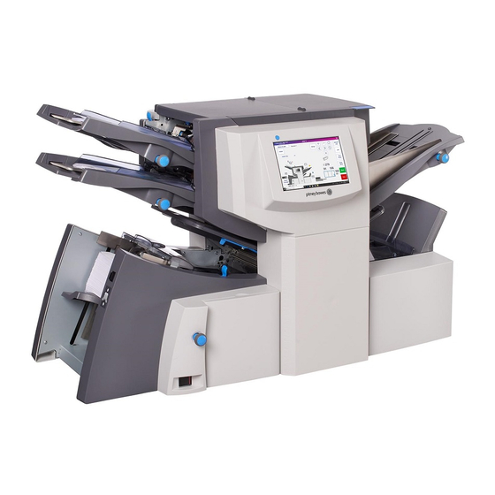
Relay Inserter Introduction
Download this manual
See also:
Operator's Manual
Shipping & Mailing
Inserter
Relay
™
Document Inserting Systems with
Touch Screen and Barcode Scanning
User Guide
International English Edition
SV63138 Rev. A
August 1, 2015
3000/4000
Table of
Contents
Previous
Page
Next
Page
1
2
3
4
5
Advertisement
Table of Contents
Troubleshooting
OMR Troubleshooting
78
Chapter 7 Troubleshooting and Error Messages
99
General Troubleshooting
101
Need help?
Do you have a question about the Relay 3000 and is the answer not in the manual?
Ask a question
Questions and answers
Related Manuals for Pitney Bowes Relay 3000
Document Inserting Systems Pitney Bowes relay 3000 Operator's Manual
Document inserting system with a standard control panel (100 pages)
Printer Pitney Bowes Relay 4000 User Manual
(120 pages)
Printer Pitney Bowes AddressRight 200 User Manual
Address printer (59 pages)
Printer Pitney Bowes ADDRESSRIGHT DA500 Operator's Manual
Pitney bowes inc. all in one printer user manual (135 pages)
Printer Pitney Bowes ADDRESSRIGHT DA750 Operator's Manual
Pitney bowes inc. all in one printer user manual (140 pages)
Printer Pitney Bowes ADDRESSRIGHT DA950 Operator's Manual
Pitney bowes inc. all in one printer user manual (120 pages)
Printer Pitney Bowes AddressRight 300 User Manual
Feeder (11 pages)
Printer Pitney Bowes ADDRESSRIGHTTM DA900 Operating Manual
Pitney bowes inc. printer user manual (108 pages)
Printer Pitney Bowes DP40S Operator's Manual
(63 pages)
Printer Pitney Bowes SendKit PB-SP100 Installation Instruction
(18 pages)
Printer Pitney Bowes AddressRight DA70S Operator's Manual
Addressright da series printer (74 pages)
Printer Pitney Bowes DA50S Service Manual
Addressright shuttlehead printers, black/black & color (127 pages)
Printer Pitney Bowes da95f Operator's Manual
Addressright da series printer (92 pages)
Printer Pitney Bowes AddressRight DA Series Operator's Manual
(83 pages)
Printer Pitney Bowes 1100 Quick Start Manual
(15 pages)
Printer Pitney Bowes DA30S, DA50S, DA55S Operator's Manual
Da series printer (73 pages)
This manual is also suitable for:
Relay 4000
Table of Contents
Print
Rename the bookmark
Delete bookmark?
Delete from my manuals?
Login
Sign In
OR
Sign in with Facebook
Sign in with Google
Upload manual
Upload from disk
Upload from URL


Need help?
Do you have a question about the Relay 3000 and is the answer not in the manual?
Questions and answers