Pitney Bowes da95f Operator's Manual
Addressright da series printer
Hide thumbs
Also See for da95f:
- Service manual (199 pages) ,
- Frequently asked questions manual (37 pages)

Related Manuals for Pitney Bowes da95f


Summary of Contents for Pitney Bowes da95f
- Page 1 AddressRight DA Series Printer ™ ™ DA95F Operator Guide International English Version...
- Page 2 Pitney Bowes or others. Pitney Bowes assumes no responsibility for any such use of the information. Except as provided in writing, duly signed by an officer of Pitney Bowes, no license, either express or implied, under any Pitney Bowes or any third party’s patent, copyright, or other intellectual property rights is granted by providing this information.
- Page 3 It is certified that the Addressing System complies with all applicable Directives of the European Union. Use only shielded USB cables for connecting to other devices. For a formal Declaration of Conformity please contact Compliance Engineering. WARNING: This is a Class A product. In a domestic environment this product may cause radio interference in which case the user may be required to take adequate measures.
-
Page 4: Table Of Contents
Table of Contents Contact Information list USA Contacts ............v Canada Contacts ............v Other Country Contacts ..........v 1 • Introduction Welcome to the DA95F Printer ......1-2 Using This Guide ...........1-2 System Requirements ...........1-2 Getting Help ............1-3 Printer Options ............1-3 Important Safety Notes ..........1-4 Printer Parts and Locations ........1-6... - Page 5 Table of Contents Cleaning the Sensors .........3-17 Cleaning the Exit and Entry Idler Rollers ....3-18 Cleaning the Transport Belts, Rollers and Printer Deck ............3-18 Setting the Separators to Account for Normal Wear ............3-19 4 • Troubleshooting Important Note About Error Codes ......4-2 Error Codes ............4-3 Problems and Solutions .........4-4 Feed Problems ............4-4...
-
Page 6: Contact Information List
My Account. • To view inventory, go to: www.pb.com and click on My Account. • To view material safety data sheets, call the Pitney Bowes Supply Line™ at: 1.800.243.7824 or go to: www.pb.com and click on Customer Support. • For direct questions, call: 1.800.522.0020. Customer Service Representatives are available Monday through Friday, 8:00 AM - 8:00 PM ET. - Page 7 Contact Information List SV61749 Rev. D...
-
Page 8: Introduction
1 • Introduction The DA95F is a versatile, easy-to-use, high speed desktop printer designed for addressing applications. This chapter explains what's in this guide, and tells you how to order supplies and where to get more information about using your DA95F. -
Page 9: Welcome To The Da95F Printer
1 • Introduction Welcome to the DA95F Printer The DA95F ink jet printer is a desktop printer used to print addresses, graphics and other information, on a wide range of material of various sizes, construction and composition. You can define the font, placement, barcode characteristics, and print quality for your addresses. -
Page 10: Getting Help
Introduction • 1 Getting Help As you use your printer, there may be times when you need help to solve a specific application problem, or you may want additional information about printer operation. Refer to the Contact Information List at the front of this guide for more information or in the separate contact sheet supplied with your printer. -
Page 11: Important Safety Notes
Important Safety Notes Follow the normal safety precautions for all office equipment: • Use only Pitney Bowes approved supplies, in particular aerosol dusters. Improper storage and use of aerosol dusters or flammable aerosol dusters, can cause an explosive-like condition that could result in a personal injury and/or property damage. -
Page 12: Other Informational Cautions
Introduction • 1 printer is plugged is free from obstruction. • Before clearing a jam, be sure printer mechanisms come to a stop. • When removing jammed material, avoid using too much force to protect against minor personal injury and damaging equipment. •... -
Page 13: Printer Parts And Locations
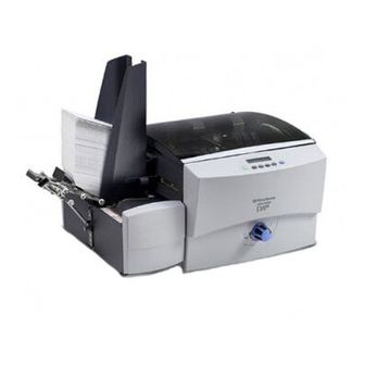
1 • Introduction Printer Parts and Locations The figure below calls out key printer components, each of which is briefly described in the text that follows. Print Station Cover Side Guides Control Panel Exit Rollers Transport Belts Media Thickness Stacker Knob Optional High Speed Stacker Connector at back of Printer (not shown). - Page 14 Introduction • 1 Idler Rollers Module A Takeaway Roller Idler Rollers Module B Tension Lever Print Head Assembly Clamp Knob (2) Print Head Assembly (Module A) Print Head Assembly (Module B) On/Off Switch USB Port Ethernet Port Analog Phone Port Power Cord Receptacle Optional...
- Page 15 1 • Introduction Optional High Speed FeedRight™ Feeder Analog Phone Port - Used to communicate with high speed FeedRight™ feeder and optional stackers. Control Panel - Use the control panel buttons to access printer menus, define print options, run the print job, and turn the printer on and off line.
- Page 16 On/Off Switch - Powers the printer on and off. Optional High Capacity Feeder - An optional high capacity feeder is available. Contact Pitney Bowes for more information. Optional Feeder Connector - A connector on the printer used to interface with an optional feeder.
-
Page 17: Printer Basics
2 • Printer Basics This chapter lists some printer specifications and describes step by step instructions for running mail. In this Chapter: Printer Features Overview ..........2-2 Setting Up A Job ..............2-4 1. Setting the Feed Gap ..........2-5 2. Setting the Angle of the Input Guide ......2-6 3. -
Page 18: Printer Features Overview
2 • Printer Basics Printer Features Overview This section provides a brief overview of the printer features. Refer to Appendix A, Specifications, for detailed specifications for the printer, including specific requirements for using each type of material. Speed (pieces per hour) Printer speed refers to the number of pieces of mail that can be processed in an hour. - Page 19 Printer Basics • 2 Width Height Thickness Minimum 5" (127 mm) 3.5" (88.9 mm) .003" (.076 mm) Maximum 14" 15.5" .5" (355.6 mm) (393.7 mm) (12.70 mm) Approved Media Types The printer can be used with booklets, catalog envelopes, postcards, self mailers, catalogs, paper and envelopes (All envelopes must be without windows and unsealed).
-
Page 20: Setting Up A Job
2 • Printer Basics Setting Up A Job Setting up a print job means adjusting the printer to accommodate the width, height, thickness and weight of your material. There are two things that determine how reliably your printer feeds: the setup adjustments and the quality of your material. A good setup minimizes misfeeds and jams. -
Page 21: Setting The Feed Gap
Printer Basics • 2 1. Setting the Feed Gap Whenever you switch from one material type to another, you need to set the gap between the separator assembly and the feed rollers before printing begins. Setting the Proper Feed Gap A. -
Page 22: Setting The Angle Of The Input Guide
2 • Printer Basics 2. Setting the Angle of the Input Guide The following suggestions for setting the feed angle are approximations only. The correct angle will be determined by the type of material you're running. It is recommended that you start with the general settings indicated below and re-adjust the angle if necessary to achieve optimal feeding. -
Page 23: Setting The Feed Ramp
Printer Basics • 2 3. Setting the Feed Ramp A. Place a piece of material on the input guide with the lead edge resting where the separator assembly and feed rollers meet. B. Lift to loosen the feed ramp adjustment lever. C. -
Page 24: Adjusting The Takeaway Roller Tension
2 • Printer Basics NOTE: proper clearance is important. If you push the side guides tight up against the stack, it could retard feeding and cause jams. If the clearance is too great, pieces could skew as they feed into the printe. 5. -
Page 25: Setting The Print Head Positions
Printer Basics • 2 6. Setting the Print Head Positions It is necessary to position the two print head assembly modules correctly over the path of the media so that your images and text will print where you want them to. A. - Page 26 2 • Printer Basics C. Tighten the clamp knob to secure the print head module in place. D. Repeat steps A through C for print head Module B. E. Feed a piece of media into the printer and then press the test envelope button to print a test piece.
-
Page 27: Setting The Idler Rollers
Printer Basics • 2 7. Setting the Idler Rollers IMPORTANT: Positioning the idler rollers correctly ensures media feeds properly through the printer and prevents the rollers from coming in contact with wet ink from the print heads. 1. Turn Thickness Knob so idler rollers are raised off of the feed belts. - Page 28 2 • Printer Basics IMPORTANT: Use these three guidelines to determine placement of the rollers. A. At least two rollers from each set (Module A and Module B) must be in contact with the media to provide equal pressure. That's a total of four rollers, two from Module A, two from Module B.
- Page 29 Printer Basics • 2 C. The rollers must be out of the path of wet ink (print zone) from the previous(up stream)module of print heads. The following illustrations show the print zone area for each module. Print Zone(Bank A) Print Zone(Bank B) Printing happens within the Print zone represents the area of grooved area of the top bracket...
-
Page 30: Adjusting The Media Thickness Knob
2 • Printer Basics 8. Adjusting the Media Thickness Knob The media thickness knob sets the distance between the print heads and the material you are running. Use it to compensate for different material thicknesses and to increase clarity of the printing. NOTE: All material in a run must be the same thickness. -
Page 31: Printing A Test Piece
Printer Basics • 2 9. Printing a Test Piece Last, you'll run some test pieces through the printer to check your setup. 1. Print one or more test pieces from the job that you are about to run to ensure the setup is correct. 2. -
Page 32: Printer Driver Software
1. Click the start button in the task bar of your Windows® desktop, then select Settings. 2. Click printers. The printer window displays. 3. Right click the Pitney Bowes printer icon, then left click the properties option. The properties window opens and displays seven tabs, each of which allows access to different printer options. -
Page 33: Using The Control Panel
Printer Basics • 2 Using the Control Panel Use the buttons on the control panel to get to the printer menus, define the print options, run a print job, and turn the printer ON LINE and OFF LINE. You’ll normally perform these actions from within the application you’re using to set up your envelope layout. - Page 34 2 • Printer Basics The buttons on the control panel perform the following functions: This Button... Does This... ON LINE • Toggles (switches) between ON LINE (communicates with host PC) and OFF LINE (no communications with host PC). • Exits the menu system. •...
-
Page 35: Using The Menus
Printer Basics • 2 Using the Menus The printer has three menus, all can be accessed through the LCD: • Use the main menu to control how your printed material looks. • Use the setup menu to configure your printer so it will function correctly with your computer. -
Page 36: Using The Main Menu
2 • Printer Basics Using the Main Menu 1. Press the ON LINE button until the LCD message displays OFF LINE. 2. To access the main menu, press the menu button. 3. Press the + or _ buttons to move through the list of menu options. -
Page 37: Main Menu
Printer Basics • 2 Main Menu MAIN MENU MENU OPTIONS ADDRESS LAYOUT DISTANCE TO RIGHT DISTANCE TO BOTTOM LINE SPACING INVERTED PRINTING ORIENTATION ORIENTATION CONTROL PRINT QUALITY QUALITY LIGHT MODE FONT NAME SIZE BOLD ITALIC BARCODE (U.S. Only) LOCATION 9 DIGIT ON/OFF BAR WIDTH ADDRESS RECOVERY GET ADDRESS (BATCH) -
Page 38: Using The Setup Menu
2 • Printer Basics Using the Setup Menu 1. Press the ON LINE button until the LCD message displays OFF LINE. 2. To access the setup menu, press the menu button. 3. Press the + or _ buttons to move through the list of menu options. -
Page 39: Setup Menu
Printer Basics • 2 Setup Menu SETUP MENU MENU OPTIONS STOP ON FEED ERROR FEEDER SETUP FEEDER TYPE ACTIVATE POLARITY PULSE TIME CONVEYOR SETUP USE CONVEYOR CONVEYOR TYPE ( IF CONVEYOR TYPE IS OTHER ) ACTIVATE POLARITY ( IF CONVEYOR TYPE IS OTHER ) PULSE TIME COMMUNICATIONS TCP/IP LINE TERMINATION... -
Page 40: Using The Service Menu
2 • Printer Basics Using the Service Menu 1. Press the ON LINE button until the LCD message displays OFF LINE. 2. To access the service menu, press and hold the menu and ( _ ) buttons simultaneously for two seconds. 3. -
Page 41: Service Menu
Printer Basics • 2 Service Menu SERVICE MENU MENU OPTIONS ADJUST PRINTING SUBMENU PRINT HEAD ADJUST MODULE A ADJUST MODULE B ADJUST CALIBRATE SENSORS PAPER SENSOR EXIT SENSOR FEEDER SENSOR SV61749 Rev. D 2-25... -
Page 42: Loading Material
2 • Printer Basics 6. Loading Material Once your printer is set up, you can load material and make a test print. Avoid misfeeds by following these precautions: A. Make sure the input area is free of dust and other matter. B. - Page 43 Printer Basics • 2 Envelopes: should be loaded so the side to be printed faces up, they should be stacked to feed with the short edge first. See example that follows. Booklets: should be stacked to feed with the sealed edge leading or stacked with the sealed edge to feed first.
-
Page 44: Output Stacker
(pieces not neatly stacked one on top of the other). This can cause envelopes to stack out of sequence. Output Stacker Optional Power Stacker An optional high capacity power stacker is available for your printer. Contact Pitney Bowes for more information. Optional Power Stacker 2-28 SV61749 Rev. D... -
Page 45: Printer Maintenance
3 • Printer Maintenance This chapter describes the procedures you should perform to keep your printer running trouble-free. In this Chapter: Replacing the Ink Cartridge(s) ...........3-2 Removing the Old Ink Cartridge(s) ........3-2 Installing New Ink Cartridge(s) ...........3-3 Replacing the Bulk Ink Cartridge(s) ........3-4 Installing New Bulk Ink Cartridge(s) ........3-5 Performing a Print Head Alignment ........3-6 Preventive Maintenance ...........3-13... -
Page 46: Replacing The Ink Cartridge(S)
3 • Printer Maintenance Replacing the Ink Cartridge(s) WARNING! The ink in the cartridge may be harmful if swallowed. Keep new and used cartridges out of reach of children. Discard empty cartridges immediately. When the control panel flashes a Low Ink warning or displays the Low Ink warning and stops printing, it is time to replace the ink cartridge indicated in the warning message. -
Page 47: Installing New Ink Cartridge(S)
Printer Maintenance • 3 Installing New Ink Cartridge(s) 1. Remove the cartridge from the shipping container by peeling the top cover off. Be careful not to touch the copper ribbon. 2. Gently remove both pieces of tape covering the ink nozzles on the cartridge. Be careful not to touch the copper nozzles. -
Page 48: Replacing The Bulk Ink Cartridge(S)
3 • Printer Maintenance Replacing the Bulk Ink Cartridge(s) Bulk ink cartridges (larger ink capacity) are available as an option for the printer. Contact your local dealer. See Contact Information in the front of this guide. WARNING! The ink in the cartridge may be harmful if swallowed. -
Page 49: Installing New Bulk Ink Cartridge(S)
Printer Maintenance • 3 Installing New Bulk Ink Cartridge(s) The bulk ink tray can hold up to six bulk ink cartridges; one to hook up to each of the six print heads. 1. Stack the bulk ink reservoirs on the bulk ink tray. -
Page 50: Performing A Print Head Alignment
3 • Printer Maintenance Performing a Print Head Alignment You'll want to perform a print head alignment each time you replace an ink cartridge. However, you only need to perform the alignment for the affected print head assembly ( A or B). Follow the step by step instructions once for print head assembly A (containing heads 1, 2 and 3) and once for print head assembly B (containing heads 4, 5 and 6) if applicable. - Page 51 Printer Maintenance • 3 5. Press the plus (+) key to scroll through the menu to the ADJUST PRINTING screen. 6. Press Enter. The PRINT HEAD ADJUST screen displays. 7. Press Enter. The VERTICAL ADJUST 1 - 2 screen displays. 8.
- Page 52 3 • Printer Maintenance 17. Press Menu to go back to the previous screen. Use the plus (+) key to scroll to the next adjustment. PRINT HEAD ADJUST screen displays. 18. Press Enter. The HORIZ ADJ: HDS 1 - 2 screen displays. 19.
- Page 53 Printer Maintenance • 3 27. Press Menu to go back to the previous screen. Use the (+) key to scroll to the next adjustment. The MODULE DISTANCE to Sensor screen displays. 28. Press Enter. The MOD TO SENSOR screen displays. 29.
- Page 54 3 • Printer Maintenance Example 1 The gap is EQUAL to .25 in (6.35 mm) No adjustment is needed. MOD TO SENSOR +LEFT 01.600 inches -RGHT 0.25 Example 2 The gap is LESS than .25 in (6.35 mm) a. Subtract the measurement on the test pattern from .25in (6.35mm) b.
- Page 55 Printer Maintenance • 3 31. Scroll using the plus (+) and minus (-) keys to change the number on the display. Press Enter. You have completed the Print Head Sensor Alignment. Go to step 32 to print a test pattern. 32.
- Page 56 3 • Printer Maintenance 33. a. Make sure the printer is OFF LINE. To do this, press the ON LINE key until the indicator light above the key goes out. b. Access the Service Menu by holding down the Menu and minus (-) keys simultaneously for two seconds.
-
Page 57: Preventive Maintenance
Printer Maintenance • 3 Preventive Maintenance The printer is designed for trouble-free service with a minimal amount of care. You should schedule regular cleaning of the feed rollers, exit rollers and lower guide. CAUTION: • Clean exterior covers with soft cloth and water. •... -
Page 58: Cleaning The Wipers
3 • Printer Maintenance CAUTION: clean print head cartridges with a soft cloth and plain water only. Abrasive materials may damage print heads. 3. From the setup menu, select 3. Purge print head. The purging process clears any clogged ink on the print nozzle. Often this returns the print quality to a normal level. -
Page 59: Purging The Print Head
Printer Maintenance • 3 Purging the Print Head 1. Be sure there is some material (paper, envelope, etc.) loaded in the printer before you go to step 2. 2. To access the setup menu, press and hold the menu button for four (4) seconds. -
Page 60: Prolonging The Life Of Print Cartridges
3 • Printer Maintenance Prolonging the Life of Print Cartridges Included in the accessories are cartridge capping assemblies. These are designed to enclose the print cartridge nozzles. Proper use of the cartridge capping assemblies helps to maintain good print quality and prevents ink from drying and clogging the print cartridge nozzles. -
Page 61: Cleaning The Sensors
Printer Maintenance • 3 Cleaning the Sensors With use, a film and/or dust builds up on the eye of the 3 sensors causing misfeeds of media. For best operation use compressed air to blow dust from the sensors, regularly. For caked on dust use a dry cotton swab to remove the dust from the eye of the sensor. -
Page 62: Cleaning The Exit And Entry Idler Rollers
3 • Printer Maintenance Cleaning the Exit and Entry Idler Rollers From normal operations of the printer the exit rollers and entry idler rollers will accumulate a buildup of ink, wax, etc. Which will require removal or the idlers will leave marks on the media. Use alcohol on a soft cloth to remove any ink, wax, etc. -
Page 63: Setting The Separators To Account For Normal Wear
Printer Maintenance • 3 Setting the Separators to Account for Normal Wear Blue Hex Nut The blue hex nut has six numbered settings. When the black separator assembly tips wear out you may need to turn the nut to the next setting. - Page 64 3 • Printer Maintenance 3-20 SV61749 Rev. D...
-
Page 65: Troubleshooting
4 • Troubleshooting This chapter lists some common printer problems and offers suggestions on how to fix them. In this Chapter: Important Note About Error Codes ........4-2 Error Codes ................4-3 Problems and Solutions............4-4 Feed Problems ..............4-4 Print Quality Problems ............4-6 Interface Problems .............4-8 Motor Problems ..............4-8 Memory Problems ..............4-9... -
Page 66: Important Note About Error Codes
4 • Troubleshooting Important Note About Error Codes When any paper handling error begins to occur frequently, the following are several maintenance actions for the operator to perform. There is a high likelyhood that performing these procedures will correct the error. If these procedures do not correct the problem then refer to the trouble shooting chart on the following pages for further actions. -
Page 67: Error Codes
Troubleshooting • 4 Error Codes Unknown Error Restart the printer Ink Empty - HD 3 Replace ink cartridge. In this example it is ink cartridge #3 (HD 3) Ink Low - HD 3 Replace ink cartridge. In this example it is ink cartridge #3 (HD 3) B, F, P, Encoder Error Call for Service... -
Page 68: Problems And Solutions
4 • Troubleshooting Problems and Solutions Before calling for service, look for your problem below. If you can solve the problem yourself, you will be able to resume printing sooner. Feed Problems Problem Reason Solution Intermittent Feed ramp not The feed ramp adds a gentle feed adjusted properly. - Page 69 Troubleshooting • 4 Misfeed (feeds Separator Assembly Adjust separator assembly double) or not set correctly. to thickness of material. See skewing Chapter 2, Printer Basics. Side guide set Check Side Guide position. See incorrectly. Chapter 2, Printer Basics. Media thickness Reduce setting.
-
Page 70: Print Quality Problems
4 • Troubleshooting Print Quality Problems Problem Reason Solution No print Ink cartridge problem Purge ink cartridge. See Chapter 3, Print Quality Problems. Clean cartridge jets with soft cotton Correct cloth and water (in the direction shown). Incorrect Light or grey Ink supply is too low. - Page 71 OFF. See Chapter printer's menu options 2, Printer Basics. If problem still is set to bold. exists, call Pitney Bowes for service. Misaligned After replacing Contact your machine supplier. test print...
-
Page 72: Interface Problems
4 • Troubleshooting Interface Problems Problem Reason Solution No commu- Incorrect printer driver Use DA95F printer driver. nications; printer does Bad ethernet or USB Replace ethernet or USB cable. not respond cable, bad printer Make sure cable connections controller board. -
Page 73: Memory Problems
Troubleshooting • 4 Memory Problems Problem Reason Solution Out of Memory The printer can run This generally means you’re out of memory when trying to use a graphic (artwork) downloading fonts or that’s too big or you have too graphics. many fonts or too large a font size. - Page 74 4 • Troubleshooting 4-10 SV61749 Rev. D...
-
Page 75: Appendix A • Specifications
Appendix A • Specifications This Appendix contains detailed hardware and material specifications for the DA95F printer. In this Chapter: Equipment Specifications ..........A-2 Material Specifications ............A-5 Envelope Sizes ............A-6 SV61749 Rev. D... -
Page 76: Equipment Specifications
Appendix A • Specifications Equipment Specifications Physical Dimensions 15" (380mm) high; 24" (609.6mm) wide; 27" (685.8mm) deep Printer Weight 88 lbs. (39.9 kg) Standard Feeder Weight 28 lbs. (12.7 kg) Combined Printer Feeder Weight 116 lbs. (52.6 kg) Electrical 100-240 Vac, 50/60 Hz. 5.0 A Interface USB 2 Type B, Ethernet RJ45 Control Language... - Page 77 Specifications • Appendix A Equipment Specifications (continued) Print Quality: With Light Mode With Light Mode set to "ON": set to "OFF": Executive 600 x 300 DPI 600 x 600 DPI Letter 300 x 300 DPI 300 x 600 DPI Draft 200 x 300 DPI 200 x 600 DPI Super Draft...
- Page 78 Idle Mode: 69.00 dBa Operating Mode: 76.00 dBa Operator position: no more than 67 dBa maximum level. Recommended Usage Pitney Bowes has tested this machine under many different conditions, and recommends that you do not exceed the usage levels specified below: •...
-
Page 79: Material Specifications
Specifications • Appendix A Material Specifications Media Size The printer can print on the following range of material sizes. Width Height Thickness Minimum 5" (127 mm) 3.5" (88.9 mm) .003" (.076 mm) Maximum 14" (355.6 mm) 15.5" (393.7 mm) .5" (12.70 mm) Material Notes Envelopes must have a flap along the long edge and are processed by the printer non-flap edge first (see illustration). - Page 80 Appendix A • Specifications Supported Envelope/Paper Sizes Paper Name Displayed in List Size (Width) Size (Height) US/Canada Envelope/Paper Sizes ENV_9 Envelope #9 8⅞" 3⅞" ENV_10 Envelope #10 9½" 4⅛" ENV_11 Envelope #11 10⅜" 4½" ENV_12 Envelope #12 11" 4¾" PPR_Booklet_9_12 Booklet 9 x 12 12"...
- Page 81 Specifications • Appendix A Paper Name Displayed in List Size (Width) Size (Height) Chou #4 Tate 90mm 205mm Hagaki 100mm 148mm Postcard #3 165mm 102mm Postcard #4 183mm 100mm **Maximum Paper Size** 14" (356mm) 15.5" (394mm) Approved Ink Cartridges HP Versatile Black C8842A HP 45 Spot Color Cartridges SV61749 Rev.
- Page 82 Appendix A • Specifications SV61749 Rev. D...
-
Page 83: Appendix B Delivery Point Bar Coding
Appendix B Delivery Point Bar Coding This Appendix contains an explanation of the benefits of using the Delivery Point Bar Code function (US mail markets only) and it also describes the various Delivery Point Bar Code formats that are available. In this Chapter: Delivery Point Bar Code function (US mail markets only) B-2 ZIP+4+2 (11 digit bar code) .......... -
Page 84: Zip+4+2 (11 Digit Bar Code
Appendix B • Delivery Point Bar Coding Delivery Point Bar Coding (US mail markets only) This printer is equipped and certified by NAIC for printing the United States Postal Service, Delivery Point Bar Code. Using Delivery Point Bar Coding (DPBC) enables the user to receive DPBC rates. The printer uses the destination data sent down on the last line from your software to print the Delivery Point Bar Code. - Page 85 Delivery Point Bar Coding • Appendix B Address Formats Table Address Data Entered Bar Code Actual Print in ZIP Codes Printed Address Block ZIP + 4 + 2 98765-123412 No DPBC 98765-1234 Printed Not Valid ZIP + 4 + 2 98765-1234~12 DPBC Printed 98765-1234 ZIP + 4 + 3 98765-1234123...
- Page 86 SV61749 Rev. D...
- Page 87 Index Approved Media A-5 Approved Media Types 2-3 bar code 11 digit A-2 bar code 12 digit A-2 Bulk Ink 3-4 Cartridge Fonts A-3 Cleaning A & B Bank Rollers 3-18 Exit and Entry Rollers 3-18 Printer Floor 3-18 Sensor 3-17 Wipers 3-14 Cleaning Printhead Cartridge 3-13 Contact Information v...
- Page 88 Index Getting Help 1-3 Glossy Material Print Quality 2-15 Ink Jet Cartridge Installing 3-3, 3-5 Installing Ink Jet Cartridge 3-3, 3-5 Interface Problems 4-8 Internal Fonts 2-2 inverted Job envelope orientation 2-3 Loading Material 2-26 Main Menu Table 2-21 Using the 2-20, 2-24 Maintenance Preventative 3-13 Material...
- Page 89 Index Operating System Recommended 1-2 Ordering Supplies v Paper Jam 4-9 Out 4-9 Petroleum Based Cleaning Solvents 3-13 Physical Dimensions A-2 Power Stacker 2-28 Print Cartridge, Replacing 3-2, 3-4 Cartridges, Prolonging Life of 3-16 Problems 4-6 Printer Driver Software 2-16 Print Head Position, Setting 2-9, 4-3 Printhead...
- Page 90 Index Sensors Cleaning 3-17 Separator Gap 2-5 Tips for Setting 2-5, 3-19 Separators Adjusting forl Wear 2-5, 3-19 Setting Up A Job 2-4 Setup Adjustments Feed Angle 2-6 Feed Gap 2-5 Feed Ramp 2-7 Idler Rollers 2-11 Media Thickness Knob 2-14 Media Thickness Lever 2-14 Print Head Positions 2-9, 4-3 Separator Gap 2-5...
- Page 91 Index Speed Printer 2-2 Stacker Optional Power Stacker 2-28 Standard 2-28 Standard Material 2-6 Technical Support v Test Piece 2-15 running a 2-15 Throughput A-3 Troubleshooting Feed Problems 4-4 Interfacing Problems 4-8 Intermittent Feed 4-4, 4-6 Memory Problems 4-9 Motor Problems 4-8 Paper Problems 4-9 Print Quality 4-6 Tyvek...
- Page 92 1 Elmcroft Road 5500 Explorer Drive Stamford, Connecticut 06926-0700 Mississauga, Ontario L4W 5C7 Canada Elizabeth Way, Harlow, Essex, CM19 5BD United Kingdom For Service or Supplies PB Form SV61749 Rev. D 8/07 © 2007 Pitney Bowes Inc. All Rights Reserved *sv61749revD*...
Need help?
Do you have a question about the da95f and is the answer not in the manual?
Questions and answers