Sign In
Upload
Manuals
Brands
Siemens Manuals
Measuring Instruments
FST020
Siemens FST020 Manuals
Manuals and User Guides for Siemens FST020. We have
1
Siemens FST020 manual available for free PDF download: Function Manual
Siemens FST020 Function Manual (194 pages)
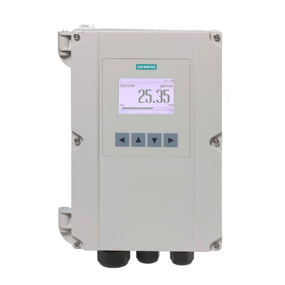
SITRANS F series Ultrasonic Flowmeters IP65 NEMA 4X
Brand:
Siemens
| Category:
Measuring Instruments
| Size: 1.56 MB
Table of Contents
Table of Contents
5
1 Introduction
15
Function Manual Scope
15
Purpose of this Documentation
15
Quick Start Wizards
15
Support
15
Product Compatibility
16
Document History
16
Device Documentation Package
16
2 Quick Start
19
Introduction
19
Quick Commissioning
19
Sensor Settings
19
Process Values
19
Inputs and Outputs
19
Copy Configuration
19
3 Setup
21
Sensor Settings
21
Length Unit
21
Length Unit - Settings
21
Pipe Settings
21
Pipe Class
21
Pipe Size
21
Outer Pipe Diameter
22
Wall Thickness
22
Pipe Material
22
Wall Sound Velocity
22
Liner Settings
23
Inner Pipe Roughness
24
Inner Pipe Diameter
24
Upstream and Downstream Conditions
24
Disturbed Flow Profile Compensation
24
Type of Upstream Condition
25
Upstream Distance
25
Type of Downstream Condition
25
Downstream Distance
25
Medium Characteristics
26
Process Medium Type
26
Expected Sound Velocity
26
Process Temperature
26
Kinematic Viscosity
27
Process Density
27
Sensor Selection
27
Sensor Model
27
Clamp-On Sensor Size
28
Nominal Sensor Frequency
28
Sensor Crystal Projection
28
Sensor Phase Velocity
28
Sensor Inactive Wedge
29
Sensor Fixed Time
29
Mounting Hole Offset
29
Spacing Offset
29
Temperature Code of the Sensor
30
Temperature Compensation Factor
30
Length of Sensor Cables
30
Path Settings
31
Installed Paths
31
Path 1
31
Path Diagnostic Alarm Limits
33
User Calibration
34
Slope
34
Path 1 Offset
34
Multipoint Calibration
35
Enable Multipoint Calibration
35
Asymmetric Calibration Table
35
Calibration Point
36
Multipoint Calibration Table
36
Flow Direction
37
Miscellaneous
37
Preamplifier Setting
37
Number of Pulses to be Transmitted
38
Minimum Ringdown Delay
38
Electronic Time Delay
38
Configuration of Test Blocks
39
About
39
Sensor Size
39
Process Values
40
Volume Flow
40
Units
40
Custom Units
40
Custom Conversion Factor
41
Decimal Places
41
Low Flow Cut-Off
41
Alarm and Warning Limits
42
Mass Flow
43
Units
43
Custom Units
43
Custom Conversion Factor
44
Decimal Places
44
Low Flow Cut-Off
44
Alarm and Warning Limits
45
Units
46
Custom Units
46
Flow Velocity
46
Custom Conversion Factor
47
Decimal Places
47
Low Flow Cut-Off
47
Alarm and Warning Limits
48
Sound Velocity
49
Units
49
Custom Units
50
Custom Conversion Factor
50
Decimal Places
50
Alarm and Warning Limits
50
Density
52
Units
52
Custom Units
52
Custom Conversion Factor
53
Decimal Places
53
Alarm Warning Limits
53
Kinematic Viscosity
55
Units
55
Decimal Places
55
Alarm and Warning Limits
55
Medium Temperature
57
Units
57
Decimal Places
57
Alarm and Warning Limits
57
Totalizers
59
Totalizer 1
59
Process Value
59
Units
60
Custom Units
60
Custom Conversion Factor
60
Decimal Places
61
Direction
61
Fail-Safe Behaviour
61
Reset
61
Preset
62
Alarm and Warning Limits
62
Inputs and Outputs
64
Alarm Status
71
Channel 2 - Output
72
Operation Mode
72
Active Operation (Read Only)
72
Fail-Safe Activation Condition
73
Current Output
73
Off Delay
76
Channel 3 - Relay
76
Operation Mode
76
Status Mode
76
Sensor Alarms (1)
77
Sensor Alarms (2)
77
Process Alarms (1)
77
Process Alarms (3)
78
Process Alarms (4)
78
Totalizer Alarms
79
Device Alarms
79
Input/Output Alarms (1)
79
Simulation Alarms (1)
80
Simulation Alarms (2)
80
Alarm Class
81
NAMUR Status Signal
81
Polarity
81
On Delay
82
Off Delay
82
Channel 4 - Input/Output
82
Operation Mode
82
Change Operation Mode
83
Frequency Output
83
Pulse Output
86
Channel 7 - Digital Input
90
Input Function
90
Channel 8 - Digital Input
90
Input Function - Settings
90
Date and Time
90
Current Date and Time
90
Set Date and Time
91
Local Display
91
FST020 - Display
91
Brightness
92
Backlight
92
Contrast
92
Damping
93
Damping Value
93
Process Values (1)
93
Process Values (2)
93
View 1
94
View
94
1St Value
94
Graph Scale Mode
94
2Nd Value
95
3Rd Value
95
4Th Process Value
96
Trend Scale Mode
97
Trend Log Time Window
97
Trend Scale Lower Limit
97
Trend Scale Upper Limit
98
View 2
98
Enable or Disable
98
View
98
1St Value
99
2Nd Process Value
99
3Rd Process Value
100
4Th Process Value
100
6Th Process Value
101
Trend Scale Mode
101
Trend Log Time Window
101
Trend Scale Lower Limit
102
Trend Scale Upper Limit
102
View 3
102
Enable or Disable
102
View
103
1St Value
103
Graphic Scale Mode
104
2Nd Process Value
104
3Rd Process Value
104
4Th Process Value
105
Trend Scale Mode
106
Trend Log Time Window
106
Trend Scale Lower Limit
106
Trend Scale Upper Limit
107
View 4
107
Enable or Disable
107
1St Value
108
2Nd Value
108
3Rd Value
109
4Th Value
109
5Th Value
110
Trend Scale Mode
110
Trend Log Time Window
111
Trend Scale Lower Limit
111
Trend Scale Upper Limit
111
View 5
112
Enable or Disable
112
View
112
1St Value
113
2Nd Value
113
3Rd Value
113
4Th Process Value
114
Trend Scale Mode
115
Trend Log Time Window
115
Trend Scale Lower Limit
115
Trend Scale Upper Limit
116
View 6
116
Enable or Disable
116
View
117
1St Process Value
117
2Nd Process Value
117
3Rd Process Value
118
4Th Process Value
118
6Th Process Value
119
Trend Scale Mode
119
Trend Log Time Window
119
Trend Scale Lower Limit
120
Trend Scale Upper Limit
120
Status Icons
120
4 Maintenance and Diagnostics
123
Identification
123
Long Tag
123
Tag
123
Descriptor
123
Message
124
Location
124
Installation Date
124
Manufacturer
124
Product Name
125
Version (Read Only)
125
Order Number (Read Only)
125
Serial Number
125
FW Version
126
HW Version
126
Final Assembly Number
126
System Type
127
Transmitter Electronics
127
HW Version
127
FW Version
127
Serial Number
127
Order Number
128
Comm. Interface Serial Number
128
Local Display
128
I/O Electronics
129
Dsl
129
Sensor
129
Type (Read Only)
129
Sensor Type (Read Only)
129
Serial Number (Read Only)
130
Sensor Type (Read Only)
130
Sensor Firmware Version (Read Only)
130
Frontend Variant (Read Only)
130
Diagnostic Events
131
Active Diagnostic Events
131
Diagnostic Log
131
Clear Diagnostic Log
131
Acknowledge Mode
131
Transmitter Detailed Events (Read Only)
132
Suppression Time
132
Enable Alarms
133
Sensor Events (1)
133
Sensor Events (2)
133
Process Events (1)
133
Process Events (2)
134
Process Events (3)
134
Process Events (4)
135
Totalizer Events
135
Device Events
135
Simulation Events (1)
136
Simulation Events (2)
136
Input/Output Events (1)
137
Assign Alarm Class
137
14 - Path 1: no Signal
137
148 - Transm. Temp. above Alarm Limit
137
149 - Transm. Temp. below Alarm Limit
138
Maintenance
138
Copy Configuration
138
Spare Part Replacement
138
Transmitter
138
Operating Time
139
Electronic Part Identification
139
Transmitter Cassette
139
Local Display
141
I/O Cassette
142
Sensor Cassette
142
Diagnostics
143
Sensor
143
Receiver Signal
143
Reynolds Number (Read Only)
143
Path 1
143
Temperature Monitoring
145
Medium Temperature
145
Transmitter Electronics Temperature
146
Inputs and Outputs
147
Channel 2 - Output
147
Channel 3 - Relay
148
Channel 4 - Input/Output
148
Calibration Picture
150
Peak Values
151
Process Value 1
151
Process Value
151
Maximum
151
Timestamp at Maximum
151
Minimum
151
Timestamp at Minimum
152
Reset Peak Values
152
Process Value 2
152
Process Value
152
Maximum
153
Timestamp at Maximum
153
Minimum
153
Timestamp at Minimum
153
Reset Peak Values
154
Process Value 3
154
Process Value
154
Maximum
154
Timestamp at Maximum
155
Minimum
155
Timestamp at Minimum
155
Reset Peak Values
155
Process Value 4
156
Maximum
156
Timestamp at Maximum
156
Minimum
156
Timestamp at Minimum
157
Reset Peak Values
157
Characteristics
157
Transmitter
157
Design (Read Only)
157
Sensorflash
158
Eject
158
Installed (Read Only)
158
Capacity Total (Read Only)
158
Capacity Available (Read Only)
159
Data Logging
159
Activation
159
Data Logging Mode
159
Logging Interval
160
Process Values
160
Simulation
161
Simulation Inputs/Outputs
161
Channel 2 - Output
161
Channel 3 - Relay
162
Channel 4 - Input/Output
163
Simulation Process Values
164
Enable Simulation
164
Volume Flow
164
Mass Flow
165
Flow Velocity
165
Sound Velocity
166
Density
166
Kinematic Viscosity
166
Medium Temperature
167
Simulate Alarms
167
Simulation Mode
167
Alarms
168
Alarm Class
170
Alarm Class
171
Audit Trail
171
Parameter Change Log
171
Clear Parameter Change Log (Write Only)
171
Firmware Update Change Log
172
Clear FW Update Change Log (Expert)
172
Self Test
172
Display Test
172
Resets
173
Restore Ordered Configuration (Write Only)
173
Device Restart (Write Only)
173
Firmware Update
173
5 Communication
175
Service Channel (USB)
175
USB Mode (Read Only)
175
Auto Mode
175
MSD Connect (Write Only)
175
Modbus (Channel 1)
176
Slave Address (SW)
176
Slave Address (HW) (Read Only)
176
Baud Rate
176
Parity / Framing
177
Floating Point Byte Order
177
Integer Byte Order
177
Register Mapping
178
Enable Mapping
178
Source Register 1
178
Target Register 1
178
Modbus Units
179
Mass Flow Unit
179
Volume Flow Unit
179
Flow Velocity Unit
180
Sound Velocity Unit
180
Density Unit
180
Kinematic Viscosity Unit
181
Temperature Units
181
Totalizer 1 Unit
181
Service Channel (USB)
182
6 Security
183
Change User PIN
183
Change Expert PIN Code (Expert)
183
Recovery ID
183
PIN Recovery
184
Activate User PIN
184
Deactivate User PIN
184
Auto Logout
184
Auto Logout
185
Logout
185
7 Language
187
Support
189
Technical Support
189
Index
191
Advertisement
Advertisement
Related Products
Siemens SITRANS FST030
Siemens FST020 IP65 NEMA 4X
Siemens SITRANS FST090
Siemens SITRANS FS230
Siemens FS20
Siemens SITRANS FS130
Siemens SITRANS FSS100
Siemens FCA2008-A1
Siemens SITRANS F FUS380
Siemens SITRANS F FS200 Utility
Siemens Categories
Industrial Equipment
Controller
Control Unit
Oven
Washer
More Siemens Manuals
Login
Sign In
OR
Sign in with Facebook
Sign in with Google
Upload manual
Upload from disk
Upload from URL