Sign In
Upload
Manuals
Brands
Kodak Manuals
Laboratory Equipment
DryView 8150
Kodak DryView 8150 Manuals
Manuals and User Guides for Kodak DryView 8150. We have
3
Kodak DryView 8150 manuals available for free PDF download: Service Manual, User Manual, Safety Manual
Kodak DryView 8150 Service Manual (470 pages)
LASER IMAGER
Brand:
Kodak
| Category:
Printer
| Size: 18.55 MB
Table of Contents
Revision History
2
Safety, Regulatory, EMC and CE Marking Compliance
3
Table of Contents
4
Section 1 - - Specifications
15
Dimensions
15
Electrical Power
15
Storage Environment
15
Operating Environment
15
Altitude
16
Floor Vibration
16
Floor Levelness
16
Floor Load
16
Environmental Effects
16
Film Size
16
Film Throughput
16
Image Input Options
16
Glossary
17
Section 2 - - Installation
21
Checklist of Installation Procedures
21
Tools Required for Installation
21
Uncrating and Initial Setup
22
Opening the Shipping Crate
22
Completing the Uncrating
23
Removing the LASER IMAGER from the PALLET
25
Checking the Accessory Materials
27
Moving the IMAGER to the Installation Site
28
Checking Site Readiness
29
Required Configuration Information
29
Unpacking
31
Removing the Packing Materials from the Back of the IMAGER
31
Removing the Packing Materials from the Front of the IMAGER
33
Installing the CHARCOAL FILTER
36
Checking that Unpacking Is Complete
37
Connecting to Electrical Power and the Network
37
Electrical Power Setup
37
Connecting to External AC Power
39
Connecting the IMAGER to the Network
40
Securing the IMAGER in Its Operating Position
40
Applying Power
41
Configuring the IMAGER
41
Setting the "Host Name" and the "IP Address
42
Checking the Port Number of the "Secure Tunnel
43
Setting the System Clock
44
Checking the Values for "DICOM Source Communications
45
Setting up Service Tracking
46
Configuring "SCP Services
46
Parameter Description
48
Parameter Description
51
Configuring the IMAGER to be a Destination
53
Configuring the LOCAL PANEL
56
Selecting the Type of Film
58
Setting up Remote Monitoring (RMS)
59
RMS Grouping
60
Checking Image Quality
63
Backing up the System Configuration
64
Training Key Operators
65
10 Editing the Service History Log
67
Guidelines for Selecting the Correct TFT Set and Related Parameters
68
Definitions
68
Selecting the Image Quality Parameters Appropriate to the
68
DICOM-GSDF-Compliant
69
Selecting Parameters for DICOM GSDF-Compliant
69
TFT Set Descriptions
73
Section 3 - - Adjustments
92
Setting Temperature of the PROCESSOR DRUM
92
Processor Drum RTD
95
Processor Film Diverter Assembly (Stripper)
96
Optics Translation Speed and SOP Delay
97
Reference Level for DENSITOMETER
99
Dynamic Range of the LASER
101
Optics Laser Power
103
Section 4 - - Disassembly/Reassembly
106
Front Door and Rear Panel Assemblies
106
Front Door Filter
106
Rear Panel
107
Film Processor Assembly
108
Processor Interface Board
108
Processor Drum
109
Processor Rollers and Related Parts
111
Processor Motor
112
Kicker Motor
114
Processor Film Diverter Assembly
116
Roller Set Assemblies
117
Densitometer Assembly
119
Densitometer Module
119
Densitometer/Exit Sensor (S9)
120
Densitometer Light Source Assembly
121
Densitometer Board
122
Local Panel Assembly
123
Film Pickup Assembly
124
Film Pickup Module
124
Film Pickup Cups
125
Film Pickup Heel Pad
126
Film Pickup Optical Sensors (S3, S4, S5, S10)
127
Film Pickup Motor (DCM2)
128
Film Pickup Vacuum Pump
129
Rollback Assembly
130
Rollback Module
130
Rollback Motor (DCM1)
132
Cartridge Present Sensor (S1)
133
Rollback Home Sensor (S2)
134
Rf Antenna Board
137
Elevator Assembly
138
Elevator Module
138
Feed Roller Assembly
141
Feed Roller Module
141
Feed Roller Torsion Springs
146
Vertical Transport Sensor (S)
148
Vertical Transport Motor (Step)
149
Imaging (Exposure) Assembly
150
Imaging Module
150
Scanner Assembly
151
Platen Film Sensor (S)
153
Optics Translation Motor (Step 4) and Capstan
155
Platen Nip Roller Belt
158
Platen Nip and Drive Rollers
159
Power Assembly
168
Dicom Raster Engine (Dre) Computer
172
Removing the Floppy Drive
178
Removing the DIMM Memory Boards
180
Removing the Dre Power Supply
181
Section 5 - - Tools/Preventive Maintenance/Cleaning
183
Required Tools
183
TEMPERATURE METER and PROBE Calibration
184
Serial Number Location
184
Preventive Maintenance
185
PM Intervals
185
Supplies Required for PM
185
EM Call Checklist
186
Cycle PM Checklist
187
Cleaning the EXPOSURE PLATEN
188
Replacing the FRONT DOOR AIR FILTER
189
Replacing the CHARCOAL FILTER
192
Removing and Checking the PROCESSOR DRUM
193
Cleaning the DRUM, HEAT SHIELD and PROCESSOR ROLLERS
195
Cleaning the FILM DIVERTER ASSEMBLY
197
Replace the PROCESSOR GASKET
199
Installing the DRUM
199
Completing the PM
201
Cleaning the OPTICS MODULE
202
Section 6 - - Theory of Operation
203
General
203
The DICOM RASTER ENGINE (DRE)
204
DRE Hardware
204
DRE Computer Hardware Components
204
Local Panel
205
Image Processing in Main Memory
206
Pcio Board
206
Digital Output Circuit
207
UART Circuit for Serial Communication with MCS
208
DRE Software
208
General Software Functions
208
Main DRE Software Components
209
Pacslink MIM
209
MIM Delivery Interface
210
DICOM Modality Preferences Database (MPDB)
212
MCS Interface Server (MIS)
212
General
212
MCS Image Server
212
MCS/MIS Command Server
213
Service Providers
213
Mcs Database Server
213
Web Server
213
Browsers for Service Laptop and Local Panel
213
Data Formatters for Service Tool and Local Panel
213
Machine Control System (Mcs)
214
Master/Slave Micro System
215
Serial Communication Protocol
215
Physical Interface
215
Mcs Board
215
Master Cpu
216
Film Processor Control
217
Stepper Motor Drive
217
Media Lookup Table (Linear Lut)
218
Laser Scanning Characteristics
218
General Pixel Flow Control Functions
218
Laser Optics Subsystem
219
Film Platen
220
Optics Module
220
Optics Translation Assembly
222
Optics Module Control Board
223
Densitometer Module
225
Step Wedge Calibration
225
Reading the Dpatch
227
Using Test Calibration Data to Create the Film Model
227
Densitometer Control Functions
228
Rf Tag Commands
229
Feeder Control Board
230
Motor Control
230
Sensor Control
231
Film Pickup and Feed Functions
231
Cartridge Elevator Functions
232
Cartridge Rollback Functions
233
Processor Interface Board
233
DC Power Supply
234
Mcs Print Sequence of Operation
234
Special Service Mode Operations
249
Purpose of Aiqc
249
Purpose of Gsm
249
Power Up, Calibration, and Print Sequence
251
Section 7 - - Troubleshooting
253
General Troubleshooting Table
253
Using the Service Tool (Service Weblink)
257
Setting Active Controls
258
Network Settings for Service Weblink
259
Accessing the SERVICE TOOL
260
Testing the DENSITOMETER
261
Running the FRU Diagnostics
262
Running the Mechanical Diagnostics
263
Running Tests of the OPTICS
266
Testing the SENSORS
269
Obtaining Film Data
271
Obtaining Dpatch Data
272
Plotting Film Calibration Data
273
Testing the LOCAL PANEL
274
Running a DRE Test Print
274
Running an MCS Transport Test
275
Obtaining a Diagnostics Summary
275
Testing Communication on the Network
277
Troubleshooting the Source of Image Problems
278
Configuration Backup
282
Configuration Restore
283
Upgrading the DRE Software -- "Ghosting
284
2--21 Reloading the MPDB through RMS
285
Using Power-On Self-Test as a Troubleshooting Tool
287
Setting up for Observation of Self-Test
287
Initialization and Self-Test Sequence Flow Charts
287
Functions of System SENSORS
297
Testing the SENSORS Using Leds
298
Via Leds
299
Testing ROLLBACK COMPLETE SENSOR S13
299
Testing SENSORS S6-S9 Via Leds
301
Troubleshooting Film Transport Problems
302
Troubleshooting Basics
302
Troubleshooting Sequence
303
Interviewing the Operator
303
Preliminary Visual Inspection
303
Preparation
303
Checking the ROLLBACK MODULE for Problems
304
Checking the FILM PICKUP MODULE for Problems
305
Cycling Film and Observing the Film Transport Process
305
Preliminary Setup
305
Checking the ROLLBACK MODULE
306
Checking the FILM PICKUP MODULE
306
Checking the FEED ROLLER MODULE
307
Checking the PLATEN MODULE
307
Remove and Inspect Suspect MODULES
308
Removing and Inspecting the ROLLBACK MODULE
308
Removing and Inspecting the FILM PICKUP MODULE
309
Removing and Inspecting the FEED ROLLER MODULE
313
Removing and Inspecting the FILM PLATEN MODULE
314
Replace the Repaired MODULE and Cycle Film to Confirm Repair
315
Troubleshooting the Sources of Film Scratches
316
Preparation for Transporting Film in the Service Mode
316
Isolating the General Area Where Scratches Are Occurring
316
Locating the Cause of Scratching in the PROCESSOR/DENSITOMETER Area
318
Locating the Cause of Scratching in the FILM PLATEN
319
Guidelines for Removing the Causes of Scratches
319
Monitoring the MCS Via a Direct CABLE Connection to the MCS BOARD
320
Using Pcanywhere
321
9. Using Scipts
322
10. Using the Logs
323
Types of Log
323
The Application Log
323
Using the Application Log
323
Log Keying Functions
325
Contents of the Log
331
Log Levels
333
DICOM Log
334
Error Tally
335
IIS Log
337
Local Panel Log
338
MCS Log
339
NT Event Log (App)
340
NT Event Log (System)
341
Print Delivery Log
342
Section 8 - - Quicksheets
343
Overview
343
Advertisement
Kodak DryView 8150 User Manual (178 pages)
Laser Imager
Brand:
Kodak
| Category:
Printer
| Size: 5.12 MB
Table of Contents
Important Notice to Purchaser:
3
License
4
End User License Agreement (EULA)
4
Limited Warranty
5
General
6
Government Restricted Rights
6
Limitation of Remedies
6
End-User License Agreement for Microsoft Desktop Operating Systems
7
Software Product License
7
Ranty
10
Warranty and Special Provisions for Canada - Limited Warranty
17
Garantie et Dispositions Particulières pour le Canada Garantie Limitée
18
Limited Warranty
19
Table of Contents
23
October
27
October
28
1 Introduction
29
Kodak Dryview 8150
29
Laser Imager
29
How the Laser Imager Works
31
Print Sequence
32
2 Operation and Maintenance
35
Operator Control of the Imager
35
Turning Imager Power on and off
36
Power on
36
Power off
36
Power Failures
38
Using the Touch Screen Local Panel
39
Home Screen
39
Screen Controls
40
Local Panel Help
42
F3319
42
Local Panel Passcodes
43
Home Screen Description
44
Film Supply Button Status Information
46
Home Screen Status Line
48
Home Screen Attention Notices
49
Film Supply Screen
50
Density Test Screen
51
Main Menu
52
System Functions Screen
54
Select Job Queue Type Screen
56
Job Details
59
System Information Menu
60
Current Errors Screen
63
Error Message Screen
64
Setup Imager Screen
65
Service Screen
76
Image Resizing
79
Operation
82
Opening the Front Door
82
Opening the Front Door Manually
83
Opening the Hood
85
Loading and Removing Film Cartridges
86
Recycling Empty Film Cartridges
87
Running a Calibration Print
87
Calibration Failure
87
Calibration Prints
87
Requesting a Calibration Print from the Local Panel
87
Requesting a Density Test
88
Local Panel Passcodes
91
Setting up Passcodes
92
Logging on to the Local Panel with a Passcode
92
Logging off
93
Key Operator Functions
93
Adjusting Local Panel Preferences
94
Displaying the Setup Local Panel Screen
94
Setting Time and Date
98
Operator Maintenance
101
Cleaning the Laser Imager
101
Replacing the Charcoal Filter
101
Preventive Maintenance
103
3 Troubleshooting
105
Correcting Errors
105
Error and Alarm Indications
105
Home Screen Status Messages
105
Error Message Screen
106
Current Errors Screen
108
Current Errors Notice on the Home Screen
109
Calibration Failure
110
Film Transport Problems
112
Manually Closing the Film Cartridge
113
Film Pickup Problems in Area 1
114
Removing Film Jams from Area 2
115
Removing Film Jams from Area 3
116
Removing Film Jams from Area 4
118
Removing Film Jams from Area 5
120
Calling for Support
121
4 Adding a Modality
125
Preparing to Add a Modality
125
Modality-Related Parameters
126
Configuration Procedure
127
Changing the Modality ID
134
Setting the Advanced Parameters
135
Selecting Film Size
136
Selecting Film Type
137
Selecting the Type of Image Resizing
138
Selecting Print Priority
139
Selecting N_Event Reporting
141
Selecting Report Warnings
142
Selecting Use of a Density Patch on the Film
142
Selecting Color Negotiation
143
Setting up the Text (Annotation) Box
144
Saving the Modality (SCU) Parameters
145
Backing up the Configuration
146
5 Optimizing Image Quality
153
Image Quality Parameters
153
Selecting the Image Quality Parameter Values
154
Non-GSDF Modalities
154
GSDF-Compliant Modalities
161
Entering the Image Quality Parameters
162
6 Specifications
165
Dimensions
165
Electrical
165
Laser Specifications
166
Operating Environment
166
Storage Environment
166
Environmental Effects
166
Film Sizes
167
Film Types
167
Film Throughput
167
Agency Compliance
167
7 Film Technical Information
169
General Description
169
Spectral Sensitivity
169
Image Quality
170
Automatic Image Quality Control
170
Environmental Impact
170
Recycling Film
171
Storing and Handling Undeveloped Film
171
Handling Developed Film
172
Archiving Developed Film
172
Dissipating Odor
172
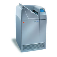
Kodak DryView 8150 Safety Manual (72 pages)
Laser Imager
Brand:
Kodak
| Category:
Laboratory Equipment
| Size: 1.92 MB
Table of Contents
Table of Contents
4
Safety and Related Information
6
Safety, Warnings, and Cautions
6
Safety Labels
10
Safety and Health Compliance
13
Safety
13
Emc
14
EU Directives
21
CE Marking
22
Note
23
Document Overview
31
Chapter 1: Introduction
32
Description
33
Programming Interface
33
Chapter 2: Hardware Description
34
General Specification
35
Functional Requirements
35
Power Supply
35
Output Power
35
RF Physical Layer
36
Required Antenna Parameters
36
Input / Output Pins (CN1 Pins 3 and 4)
36
Baseband Receiver
37
Connector Details
38
16-Pin Header Connector CN1
38
RI-STU-TRDC-02 (CN1) Pin Assignments
39
Mechanical Specifications
40
RI-STU-TRDC-02 with 16-Pin Straight Header Connector
40
Chapter 3: Reader Protocol
41
Serial Protocol Definition
42
Request Packet Format (Host to Reader)
42
Response Packet Format (Reader to Host)
43
Command Flags Request
43
Command Flags Response
44
Bcc
44
Example Request Packet
44
Command Definitions
45
Tag-It HF Command Definitions
45
Miscellaneous Commands
48
ISO/IEC 15693 Part 3 Transmission Protocol
52
ISO/IEC 15693-3 Command Codes
52
Request/Response Packet Format for ISO/IEC 15693-3
53
Mandatory Commands
56
Optional Commands
58
Chapter 4: Regulatory and Warrenty Notices
68
Regulatory Notes
69
FCC Notices (U.S.A.)
69
R&TTE Conformity (Europe)
69
Warranty and Liability
69
Appendix A: Downloading Data to FLASH Memory
70
Appendix B: Error Codes
71
Advertisement
Advertisement
Related Products
Kodak DryView 8100
Kodak 8100844 - PalmPix Digital Camera
Kodak 8161960 - EasyShare Printer Dock Series 3 Photo
KODAK 8194680
Kodak 8116253 - PRO 1400 Photo Printer
Kodak 819900014051
Kodak 819900014037
Kodak 819900014044
Kodak 819900014174
Kodak 819900014150
Kodak Categories
Digital Camera
Scanner
Printer
All in One Printer
Projector
More Kodak Manuals
Login
Sign In
OR
Sign in with Facebook
Sign in with Google
Upload manual
Upload from disk
Upload from URL