Table of Contents
Advertisement
Advertisement
Table of Contents

Related Manuals for A&D HW-10KGL


Summary of Contents for A&D HW-10KGL
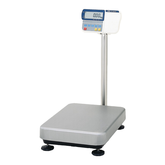
- Page 1 Digital Platform Scale HV-15KGL HV-15KGV HV-60KGL HV-60KGV HV-200KGL HV-200KGV HW-10KGL HW-10KGV HW-60KGL HW-60KGV HW-100KGL HW-100KGV HW-200KGL HW-200KGV HW-300KGL4 HW-300KGV4 HW-600KGL4 HW-600KGV4 HW-600KGL3 HW-600KGV3 HW-1200KGL3 HW-1200KGV3 1WMPD4000041D...
- Page 2 This is a hazard alert mark. This mark informs you about the operation of the product. Note This manual is subject to change without notice at any time to improve the product. No part of this manual may be photocopied, reproduced, or translated into another language without the prior written consent of A&D Company, Limited.
-
Page 3: Table Of Contents
Contents Compliance ....................3 1.1. Compliance with FCC rules..............3 Outline and Features ................. 4 Unpacking ....................5 3.1. Accessories and Options List..............7 Precautions ....................9 4.1. Installing the Scale ................. 9 4.2. Operating the Scale ................9 4.3. Storing the Scale..................9 Installing the Scale................... - Page 4 Upper/Lower Comparator Function............36 11.1. Preparation (Setting Parameters) ............37 11.2. Operation and Performance (Examples)..........39 Full/Dribble Batch Function..............40 12.1. Preparation (Setting Parameters) ............42 Simple Batch Function................. 44 13.1. Preparation (Setting Parameters) ............45 13.2. Operation and Performance (Examples)..........46 Calibration (Adjusting the Scale)............
-
Page 5: Compliance
1. Compliance 1.1. Compliance with FCC rules Please note that this equipment generates, uses and can radiate radio frequency energy. This equipment has been tested and has been found to comply with the limits of a Class A computing device pursuant to Subpart J of Part 15 of FCC rules. These rules are designed to provide reasonable protection against interference when this equipment is operated in a commercial environment. -
Page 6: Outline And Features
2. Outline and Features The HV-G series are platform scales with 1/3000 resolution, and have the triple weighing range function to select the weighing range. The HW-G series come with two types of resolution; 1/6000 : HW-300KGL4, HW-300KGV4, HW-600KGL4, HW-600KGV4, HW-600KGL3, HW-600KGV3, HW-1200KGL3 and HW-1200KGV3. -
Page 7: Unpacking
3. Unpacking Models Models Display Unit Display Unit HV-15KGL HV-60KGL HV-60KGV HV-15KGV HW-60KGL HW-60KGV HW-10KGL HW-10KGV Base Unit Display Unit Models Base Unit HV-200KGL HV-200KGV Caution HW-100KGL HW-100KGV Do not pull the load cell cable. HW-200KGL HW-200KGV Accessories Refer to "Accessries List" on page 7. - Page 8 Models Models Display Unit HW-600KGL3 HW-300KGL4 Display Unit HW-300KGV4 HW-600KGV3 HW-1200KGL3 HW-600KGL4 HW-1200KGV3 HW-600KGV4 Base Unit Base Unit Caution Caution Do not pull the Do not pull the load cell cable. load cell cable. Accessories Refer to "Accessories List" on the next page. Accessories supplied depend on the scale model. AC adapter Please confirm that the AC adapter type...
-
Page 9: Accessories And Options List
Cable tie (1) HW-1200KGV3 adjustment (1) 4 mm screw for display unit installation (2) Display unit cover (1) HV-15KGL AC Adapter (1) HW-10KGL Instruction manual (1) HV-60KGL Display unit cover (1) HV-200KGL Allen wrench (1) HW-60KGL AC Adapter (1) - Page 10 Options List Order code / Option name Accessories OP-02 Extension load cell cable (For weighing capacity of 10 kg to 200 kg) Tapping screw M4x10 Extension load cell cable (For weighing capacity of 300 kg to 1200 kg) OP-03 RS-232C interface/ Relay output/ Buzzer Connector JA:TCP0586 Connector TM:BLA9...
-
Page 11: Precautions
4. Precautions 4.1. Installing the Scale Consider the following conditions to get the most from your scale. Install the scale where the temperature and relative humidity is stable, there is no draft and a stable power source is available. Install the scale on a solid and level surface. Do not install the scale in direct sunlight. -
Page 12: Installing The Scale
5. Installing the Scale 5.1. Setting up the Scale The setup procedure depends on the scale model. Refer to the table below. Models Refer to HV-15KGL/HV-15KGV/HV-60KGL/HV-60KGV/HV-200KGL/HV-200KGV/HW-10KGL Procedure A HW-10KGV/HW-60KGL/HW-60KGV/HW-100KGL/HW-100KGV/HW-200KGL/HW-200KGV HW-300KGL4/HW-300KGV4/ HW-600KGL4/HW-600KGV4 Procedure B HW-600KGL3/HW-600KGV3/ HW-1200KGL3/HW-1200KGV3 Procedure C 5.1.1. Procedure A... -
Page 13: Procedure B
5.1.2. Procedure B HW-300KGL4/HW-300KGV4 HW-600KGL4/HW-600KGV4 Note The display unit, the pole and the base unit are connected using cables. So, use care when lifting the display unit. Step 1 Take the base unit, pole and display unit out, taking care not to pull on the load cell cable. -
Page 14: Procedure C
5.1.3. Procedure C HW-600KGL3/HW-600KGV3 HW-1200KGL3/HW-1200KGV3 Note The display unit, the pole and the base unit are connected using cables. So, use care when lifting the display unit. Step 1 Take the scale out. The pole, the display unit and the accessories are found inside the base unit. -
Page 15: Installing The Batteries For Type L
5.2. Installing the Batteries for Type L Step 1 Turn off the display. Remove the AC adapter. Step 2 Press and slide the ext. cover to open it. Press the hook of the int. cover to the left side and lift it. Step 3 Insert six new batteries with proper polarity (+,-). -
Page 16: Removing The Pole
Avoid dust, static electricity and high humidity (or condensation) because the inside of the display unit is sensitive. The pole removing procedure depends on the scale model. Refer to the table below. Models Refer to HV-15KGL/HV-15KGV/HV-60KGL/HV-60KGV/HV-200KGL/HV-200KGV/HW-10KGL Procedure A HW-10KGV/HW-60KGL/HW-60KGV/HW-100KGL/HW-100KGV/HW-200KGL/HW-200KGV HW-300KGL4/HW-300KGV4/HW-600KGL4/HW-600KGV4/HW-600KGL3/HW-600KGV3 Procedure B HW-1200KGL3/HW-1200KGV3 5.3.1. -
Page 17: Procedure B
Step 9 Wind the cable through the ferrite core two times. Affix the cable to the rear cover using the cable clamp. Step 10 Connect the cable to the connector. Close the rear cover. Step 11 Check the weighing accuracy. 5.3.2. -
Page 18: Grounding The Scale
When using where there may be static electricity, ground the scale. The grounding procedure depends on the scale model. Refer to the table below. These procedures are only for grounding part of the scale. Models Refer to HV-15KGL/HV-15KGV/ HW-10KGL/HW-10KGV Procedure A HV-60KGL/HV-60KGV/HV-200KGL/HV-200KGV/HW-60KGL/HW-60KGV Procedure B HW-100KGL/HW-100KGV/HW-200KGL/HW-200KGV... -
Page 19: Description Of Each Part
6. Description of Each Part 6. Description of Each Part HV-G/HW-G Series Page 17... - Page 20 6. Description of Each Part Page 18 HV-G/HW-G Series...
-
Page 21: Display And Symbols
6.1. Display and Symbols Display and Symbols Description Stability mark When the current weight value is stable, this mark is displayed. It means a proper condition that this value is readable. Zero point mark When the key is pressed with nothing on the pan, ZERO this mark is displayed. - Page 22 Display and Symbols Description Counting mode (Example) This mode uses the stored unit mass and counts the number of articles on the pan. The unit is Storing the unit mass for the counting mode (Example) The unit mass is stored, using 20 pieces of samples. The zero value means that no articles are on the pan.
-
Page 23: Keys
isplay and Symbols Description Calibration error The calibration mass is too heavy. Check the base unit and the weighing pan. Does not display zero when the scale is turned on. Remove anything that is on the weighing pan. Perform zero point calibration. The weight value is unstable due to drift or vibration when the scale is turned on. - Page 24 Function table: used to select a parameter. Display and Symbols Description SET key, key Normal weighing mode: used to turn the comparator on or off. (Refer to f6 ) Counting mode: used to enter the mode to store the unit mass.
-
Page 25: Basic Operation
7. Basic Operation 7.1. Turning the Scale on/off and Weighing 7.1.1. Type V or Type L with AC Adapter Step 1 Ground the scale. Step 2 Confirm that nothing is placed on the pan. Step 3 Confirm that local voltage and receptacle type are correct. Step 4 The scale turns on/off using the key alternately. -
Page 26: Type L With Batteries
7.1.2. Type L with Batteries Step 1 Install six new batteries. Refer to "5.2. Installing the Batteries for Type L". Step 2 Confirm that nothing is placed on the pan. Step 3 The scale turns on/off using the key alternately. ON/OFF Step 4 Check the accuracy of weighing. -
Page 27: Tare (And Net Display)
7.2. Tare (And Net Display) The "tare" is used to cancel the mass of a container, which is placed on the pan to contain the article to be weighed. Caution The tare reduces the weighing range. The current tare value is reset by pressing the key or turning the scale ZERO off. -
Page 28: Weighing Range For The Hv-G Series
7.3. Weighing Range for the HV-G Series This is the function to select a weighing range for the HV-G series. The mass value is displayed within a selected range. Select automatic range (f2 0) or manual range (f2 1) in the function table. Operation and Performance Function table Description... -
Page 29: Mode Key (Changing Unit And Mode)
7.4. Mode Key (Changing Unit and Mode) Pressing the key changes the display as follows. Refer to function table f3 for MODE units. Usable units are according to the factory settings. If the law in your area Pound permits, you may use all of the units. - Page 30 Description The status of "Inactive comparator ( )" is that comparator function ( f6 0 f6 2 f6 4 ) is selected and this comparator is not used. The comparator can be selected to f6 6 be ON or OFF using the SET key alternately. The following parameters are stored in the same memory.
-
Page 31: Counting Mode
8. Counting Mode The counting mode is the function to convert the total mass value (total weight) of articles to a count, when each article has the same mass value. To use this function, store a unit mass in advance. Even if the AC adapter or the batteries is removed, the unit mass is maintained in non-volatile memory. -
Page 32: Counting The Number Of Articles
8.2. Counting the Number of Articles Step 1 Press the key to display the unit MODE Step 2 Store the unit mass of the article. Refer to "8.1. Storing a Unit Mass" Step 3 Place the container on the pan. Press the key. -
Page 33: Percentage Mode
9. Percentage Mode The percentage mode is the function to display a mass value in the unit of "%". To use this function , store a 100% mass value in advance. The 100% mass value is stored in the scale even if the power is removed. 9.1. -
Page 34: Reading The Percentage
9.2. Reading the Percentage Step 1 Press the key to display the unit %. MODE % Percentage mode Step 2 Store the 100% mass of the article. Storing a 100% mass Refer to "9.1. Storing a 100% Mass " A container(bowl) Step 3 Place the container on the pan. -
Page 35: Accumulation Function
10. Accumulation Function This function counts the number of times articles are weighed, calculates the total mass value and can display the number (accumulation count) and accumulated mass value. The accumulation function is displayed with up to 6 digits. The balance can not display 7 or more digits, therefore the leading digits are not displayed. -
Page 36: Preparation (Setting Parameters)
Function table Description When the display is a positive stable value and not nearly-zero, the scale accumulates the data automatically. The next accumulation f8 3 can be performed after the display becomes nearly-zero or a negative value. When the display is a stable value and not nearly-zero, the scale accumulates the data automatically. -
Page 37: Operation And Performance (Examples)
10.2. Operation and Performance (Examples) Example 1 In this example, the scale accumulates the value each time an article is weighed. The function parameter is set to f8 3 . Step 1 Press the key to display MODE Step 2 Press the key to reset the accumulation data. -
Page 38: Upper/Lower Comparator Function
11. Upper/Lower Comparator Function This function compares a weight value with the upper limit (HI) and the lower limit (LO) and displays the results. To use this function, set the "Comparator function ( )" parameters in the f6 0 f6 7 function table, upper limit value (HI) and lower limit value (LO). -
Page 39: Preparation (Setting Parameters)
Function table Description When the weight value becomes stable and not nearly-zero, the f6 7 scale compares the value. It does not compare on an unstable condition. Caution The upper limit value (HI) must be greater than the lower limit value (LO). The parameters of the upper limit value (HI) and the final value (HI) use the same memory. - Page 40 Step 5 If either of has been f6 0 f6 2 f6 4 f6 6 selected, press the key to use the comparator. Step 6 Press the key to display the blinking HI. MODE Step 7 Set the upper limit value using the following keys. Selecting the figure to be changed.
-
Page 41: Operation And Performance (Examples)
11.2. Operation and Performance (Examples) Example 1 This example is set as follows: Function table (The scale always compares the weight value f6 1 even when the value is nearly-zero.) Upper limit value (HI) 7.000 kg Lower limit value (LO) 6.500 kg Case The comparison starts when the scale is turned on. -
Page 42: Full/Dribble Batch Function
12. Full/Dribble Batch Function This function changes the scale to a filling machine which sub-divides a bulk product ( like grain) into loads of predetermined and virtually constant mass. To use this function, set the parameter of the "Comparator function ( )", f6 9 "... - Page 43 Caution The comparison of the full/dribble batch function can not be restored. (One way sequence). If the weight value becomes less than the final value after the value reached a predetermined target value, neither HI nor LO is on. The parameters of the upper limit value (HI) and the final value (HI) use the same memory.
-
Page 44: Preparation (Setting Parameters)
12.1. Preparation (Setting Parameters) Step 1 Turn off the display. Press and hold the key and press the key. ZERO ON/OFF The function table is displayed. Step 2 Press the key to display an item of the ENTER comparator function ( Step 3 Select a parameter of the full/dribble batch function ) with the key. - Page 45 Step 8 Press the key to display the blinking HI (of the MODE final value). Step 9 Set the final value using the following keys. Selecting the figure to be changed. < Changing the number of the figure. ∧ Step 10 Press the key to store the new parameter and ENTER display the blinking OK (of preliminary value).
-
Page 46: Simple Batch Function
13. Simple Batch Function This function compares a weight value with the final value, preliminary value and zero band for the full/dribble batch function. The result is indicated by zero band (LO indicator), full flow (HI indicator) and dribble flow (OK indicator). Even if the weight value is increasing or decreasing, this function can compare it. -
Page 47: Preparation (Setting Parameters)
Caution The parameters of the upper limit value (HI) and a final value (HI) use the same memory. The parameters of the lower limit value (LO) and the preliminary value (OK) use the same memory. The upper/lower comparator function, the simple batch function and the full/dribble batch function can not be used at the same time because these parameters use the common memory. -
Page 48: Operation And Performance (Examples)
Step 6 Press the key to display the blinking HI (of the MODE final value). Step 7 Set the final value using the following keys. Selecting the figure to be changed. < Changing the number of the figure. ∧ Step 8 Press the key to store the new parameter and ENTER display the blinking OK (of preliminary value). -
Page 49: Calibration (Adjusting The Scale)
14. Calibration (Adjusting the Scale) The scale is an instrument which weighs the "weight" and displays its "mass". Calibration is the adjustment function so that the scale can weigh correctly. Three steps of calibration are available Gravity Acceleration Correction ... The function to correct the scale’s local gravity acceleration, so that the scale functions correctly when the calibrated scale has been moved to a distant place. -
Page 50: Gravity Acceleration Table
14.1. Gravity Acceleration Table Amsterdam 9.813 m/s Manila 9.784 m/s Athens 9.800 m/s Melbourne 9.800 m/s Auckland, NZ 9.799 m/s Mexico 9.779 m/s Bangkok 9.783 m/s Milan 9.806 m/s Birmingham 9.813 m/s New York 9.802 m/s Brussels 9.811 m/s Oslo 9.819 m/s Buenos Aires 9.797 m/s... -
Page 51: Complete Calibration Procedure
14.2. Complete Calibration Procedure 14.2.1. Gravity Acceleration Correction Step 1 Turn on the display. Open the rear cover of the display unit. Locate the CAL switch inside. Press and hold the switch to enter the calibration mode. Then is displayed. Cal 0 Step 2 Press the key to enter the gravity acceleration... -
Page 52: Calibration Of The Zero Point
14.2.3. Calibration of the Zero Point Step 8 After 30-minute warm up, press and hold the switch to enter the calibration mode. Then the is displayed. Cal 0 Step 9 Confirm that nothing is placed on the pan. Wait for the stability mark to be displayed. Press the key. -
Page 53: Function Table
15. Function Table The function table is used to store and refer items that determine the performance of the scale. Each item has a parameter. The parameters are stored in the scale even if the power is removed. 15.1. Parameter Setting Procedure Step 1 Turn off the display. -
Page 54: Parameter List
15.2. Parameter List A Item Display Description A The type L scale is turned off after 5 minutes of no operation, when zero is displayed. A Automatic f1 0 # Not used A turning off f1 1 Used A Selects how to change the weighing range for HV-L and HV-G A... - Page 55 A Item Display Description When the weight value becomes stable after the key is Comparator pressed, the scale compares the weight value. It does not compare f6 4 on an unstable condition. Press the key again to stop the comparison. When the weight value is stable, the scale compares the weight f6 5 value.
- Page 56 A Item Display Description Accumulation When the display is a stable value and not nearly-zero, the scale function accumulates the data automatically. The next accumulation can be performed after the display becomes nearly-zero. f8 4 Recording the number and mass of articles removed from the pan.
- Page 57 A Item Display Description A Selects the method to hold the current weight value. When the weight value becomes nearly-zero or changes more than 25% A +30 digits, hold display is canceled. A Hold f12 0 # Not used A f12 1 The hold function is ON or OFF alternately by the key.
-
Page 58: Rs-232C Serial Interface
16. RS-232C Serial Interface Note When the RS-232C serial interface is used, be sure to set the “Address ( ) “ to “( )”. RS-232C interface has the following two modes. Stream mode Outputs data continuously and can be used to print data. Command mode Controls the scale using commands from a computer. -
Page 59: Data Format
16.1. Data Format Bit Format Format 1 There are four headers for the type of data and weighing condition. Stable weighing data Unstable weighing data Stable counting data Out of range ( Over) The weight value consists of 9 characters including decimal point and polarity. The polarity is always output. - Page 60 Format 2 There are four headers for the type of data and weighing condition. Stable weighing data Unstable weighing data Stable counting data Out of range The weight value consists of 7 characters including decimal point and polarity. The polarity is always output. There are three units.
-
Page 61: Stream Mode
16.2. Stream Mode The scale outputs the current weighing data at the time the display is refreshed. The scale does not output data while in the setting mode. Averaging of function table Refresh rate f13 0 Fast response Approximately 7 times/s while the display is unstable, Sensitive value Approximately 4 times/s when the display is stable f13 1... -
Page 62: Command Mode
16.3. Command Mode The command mode is the function which can perform "outputting data", "controlling the scale" and "setting parameters" by a command transmitted from a computer Caution Allow at least 500 milliseconds between commands. 16.3.1. Command List The following explanation uses “Format 1 ( f15 0 )" Data output The current weighing data is output. -
Page 63: Preset Tare
Preset tare Tare value is set and the net is displayed. The set value is a 5 digit numerical value with a polarity sign and does not contain a decimal point. Template PT, [parameter] Command Reply Net is displayed and the net mark is displayed. Upper limit value The upper limit value is stored. - Page 64 Final value The final value is stored. The set value is a 5 digit numerical value with a polarity sign and does not contain a decimal point. Template S0, [parameter] Command Reply The value is stored. Preliminary value The preliminary value is stored. The set value is a 5 digit numerical value with a polarity sign and does not contain a decimal point.
-
Page 65: Example Of Setting Parameters
16.3.2. Example of Setting Parameters Step 1 Turn off the display. Press and hold the key and press the key. ZERO ON/OFF The function table is displayed. key to display f4 ("Baud rate"). Step 2 Press the ENTER Select a parameter of "Baud rate" with the key. -
Page 66: Options
17. Options 17.1. Extension Load Cell Cable (OP-02) This cable is used for installing the indicator away from the base unit. This extension load cell cable is 5 m long. Refer to " 5.3. Removing the Pole" for how to remove the pole. Caution Calibrate the scale after connecting this cable. - Page 67 For models with weighing capacity of 300 kg to 1200 kg HV-G/HW-G Series Page 65 17. Options...
-
Page 68: Rs-232C/ Relay Output/ Buzzer (Op-03)
17.2. RS-232C/ Relay Output/ Buzzer (OP-03) Note When the OP-03 is used, be sure to set the "Address ( ) " to "( )". Replace the standard RS-232C interface with this option. Refer to " RS-232C Serial Interface" for its specification. The following optional cables can be used, when you do not use the relay output. - Page 69 Installing OP-03 Step 1 Remove two screws that attach the RS-232C board on rear of the display unit. Remove the RS-232C board. Step 2 Switch the connections. Step 3 Insert the option board into the display unit and affix with the screws.
-
Page 70: Rs-422/ Rs-485 / Relay Output (Op-04)
17.3. RS-422/ RS-485 / Relay Output (OP-04) Replacing with the standard RS-232C interface, the RS-422/ RS-485 interface can connect up to 16 scales and control them from a computer. The RS-422/ RS-485 interface has the following two modes. Stream mode Outputs data continuously. - Page 71 Circuits Relay 47kΩ RS-422 input RS-485 input 47kΩ 4.7kΩ 4.7kΩ 120Ω RS-422 output RS-485 output SDA SDB RDA RDB TRM HI LO COM RS-422/485 terminal Relay output AC adapter jack Caution Please confirm that the AC adapter type is correct for your local voltage and receptacle type.
- Page 72 An Example of Connection The polarities (A, B) of the host computer signal depends on the computer model. RS-422 RS-485 Terminator Terminator (May be built in the (May be built in the host computer) host computer) Host computer Host computer HV-G/HW-G HV-G/HW-G Address=01...
-
Page 73: Communication Format
17.3.1. Communication Format Commands consist of an address and the same command as for the RS-232C. The address of the equipment is inserted in the first part of the command. Commands return the same command when the communication format is and there is no transmitting data. - Page 74 Zero The current mass value is set to the zero point. This is the same as the key. ZERO Template Command Reply The mass value becomes zero and zero point mark is displayed. Tare With a tare (container) placed, the current mass value is set to zero, and the net is displayed.
- Page 75 Accumulation data output Accumulated data is output. Template Command Reply Accumulation count output Number of accumulations is output. Template Command Reply Reset of accumulation data and accumulation count Accumulated data and number of accumulations become zero. Template Command Reply Data and number of accumulations become zero. Final value The final value is stored.
-
Page 76: Built-In Printer For Type V (Op-06)
17.4. Built-in Printer for Type V (OP-06) To use the printer, set the parameter of the "Print mode ( )" in the function table. To print the date, set the parameter of the "Date ( )" in the function table. Caution The date parameter is not updated automatically. - Page 77 Installing the Printer Paper (Special roll paper) Step 1 Open the cover. Step 2 Cut the paper end for easy insertion. Step 3 Install the paper end and press the F and PRINT keys at the same time. (Paper Feed) Step 4 Arrange the ribbon using the dial.
-
Page 78: Specifications
18. Specifications HV-G Series A HV-15KGL HV-60KGL HV-200KGL Models HV-15KGV HV-60KGV HV-200KGV A Weighing Capacity [kg] A Min. weighing (1 digit) [g] A Weighing Capacity [lb] A Min. weighing (1 digit) [lb] 0.002 0.005 0.01 0.01 0.02 0.05 0.05 A Weighing Capacity [oz] 2400... - Page 79 HW-G Series (Weighing Capacity: 10 kg to 200 kg) A HW-10KGL HW-60KGL HW-100KGL HW-200KGL Models HW-10KGV HW-60KGV HW-100KGV HW-200KGV A Weighing Capacity [kg] A Min. weighing (1 digit) [g] A Weighing Capacity [lb] A Min. weighing (1 digit) [lb] 0.002 0.01...
- Page 80 HW-G Series (Weighing Capacity: 300 kg to 1200 kg) A HW-300KGL4 HW-600KGL4 HW-600KGL3 HW-1200KGL3 Models HW-300KGV4 HW-600KGV4 HW-600KGV3 HW-1200KGV3 A Weighing Capacity [kg] 1200 A Min. weighing (1 digit) [g] A Weighing Capacity [lb] 1500 1500 3000 A Min. weighing (1 digit) [lb] A...
- Page 81 Dimensions Unit: mm 18. Specifications HV-G/HW-G Series Page 79...
- Page 82 Unit: mm 18. Specifications Page 80 HV-G/HW-G Series...
-
Page 83: Maintenance
19. Maintenance Refer to "4. Precautions" for use. Refer to "6.1. Display and Symbols " and corresponding mode for displayed error code. Refer to "14. Calibration (Adjusting the Scale)" for precision weighing. Periodically check the accuracy of the weighing. Calibrate the scale, if it has been moved to another location or the environment has changed. - Page 84 MEMO Page 82 HV-G/HW-G Series...
- Page 85 MEMO HV-G/HW-G Series Page 83...
- Page 86 MEMO Page 84 HV-G/HW-G Series...