
Related Manuals for A&D HW-200KV-WP


Summary of Contents for A&D HW-200KV-WP
- Page 1 Waterproof Digital Platform Scale HV-15KV-WP HV-60KV-WP HV-200KV-WP HW-10KV-WP HW-60KV-WP HW-100KV-WP HW-200KV-WP 1WMPD4000211B...
- Page 2 This is a hazard alert mark. This mark informs you about the operation of the product. Note This manual is subject to change without notice at any time to improve the product. No part of this manual may be photocopied, reproduced, or translated into another language without the prior written consent of the A&D Company.
-
Page 3: Table Of Contents
Contents Compliance ................ 3 1.1.1. Compliance with FCC rules............3 1.1.2. Classification of protection provided by enclosures ....3 Outline and Features............4 Unpacking ................5 3.1. Accessories and Options list ............6 Caution................7 4.1. Precautions for Installing the Scale ..........7 4.2. - Page 4 12.1. Preparation (Setting Parameters)..........35 Simple Batch Function ............. 37 13.1. Preparation (Setting Parameters)..........38 13.2. Operation and Performance (Examples) ........39 Calibration (Adjusting the Scale) ........40 14.1.1. The Gravity Acceleration Table..........41 14.2. The Complete Calibration Procedure .......... 42 14.2.1.
-
Page 5: Compliance
1. Compliance 1.1.1. Compliance with FCC rules Please note that this equipment generates, uses and can radiate radio frequency energy. This equipment has been tested and has been found to comply with the limits of a Class A computing device pursuant to Subpart J of Part 15 of FCC rules. These rules are designed to provide reasonable protection against interference when this equipment is operated in a commercial environment. -
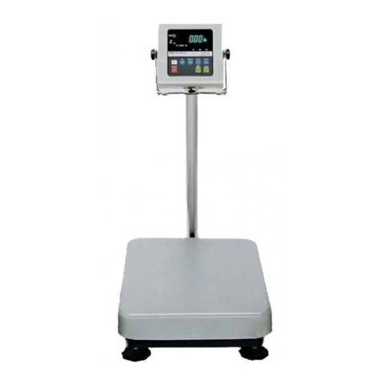
Page 6: Outline And Features
2. Outline and Features These scales are designed to comply with IP-65 of IEC 529 The HV-WP series is a platform scale with 1/3000 resolution, and has a "triple weighing range" function to select the weighing range. The HW-WP series is a platform scale with 1/10000 resolution. The scales have a fluorescent display so the weighing value can be read in dim light. -
Page 7: Unpacking
Base Unit Main power cord Display Unit Models Base Unit HV-200KV-WP HW-100KV-WP Caution HW-200KV-WP Do not pull the load-cell cable. Main power cord Main power Please confirm that the local voltage and receptacle type are correct for your scale. All Accessories Refer to the accessries list on the next page. -
Page 8: Accessories And Options List
RS-232C interface/ Relay output/ Buzzer Connector JA:TCP0586 OP-04 RS-422/485 interface / Relay output Connector TM:BLA9 OP-13 Roller conveyor for HV-200KV-WP, HW-100KV-WP and HW-200KV-WP OP-14 Roller conveyor for HV-60KV-WP and HW-60KV-WP AX-KO577A-200 RS-232C cable, D-sub 25 pin, 2m AX-KO1786-200 RS-232C cable, D-sub 9 pin, 2m AX-KO577A-200 AX-KO1786-200 3. -
Page 9: Caution
4. Caution 4.1. Precautions for Installing the Scale Ground the scale, so that the user will not be subjected to an electric shock. Do not handle the Main power cord with wet hands. The AC plug is not water-resistant. Install it in an area where it does not get wet. Do not install the scale where there is flammable or corrosive gas present. -
Page 10: Installing The Scale
5. Installing the Scale This procedure includes all of the steps for installing the HV-WP series and HW-WP series. Therefore, on some models, there are some unnecessary steps. Pole Cable Step 1 Connect the indicator unit to the pole with the Indicator accesory knobs and rubber washers. -
Page 11: Removing The Pole
Step 5 Remove four 3mm screws from the bottom cover Pole of the bracket for HV-60KV-WP, HV-200KV-WP, HW-60KV-WP, HW-100KV-WP, HW-200KV-WP. Bracket (Middle and large size) Step 6 Carefully remove the load cell cable from the pole and the bracket. Especially, use care with... - Page 12 Allen head screw requires the following allen wrench. HV-15KV-WP, HV-200KV-WP, HV-60KV-WP, HW-100KV-WP, HW-10KV-WP, HW-200KV-WP HW-60KV-WP 5mm Allen wrench 6mm Allen wrench Bracket Step 9 Wind the cable through the ferrite core two times. Affix the cable to the rear cover using the cable clamp.
-
Page 13: Grounding The Scale
(Part of “ ”) Levering feet Procedure B HV-60KV-WP, HV-200KV-WP, HW-60KV-WP, HW-100KV-WP, HW-200KV-WP Secure the grounding cable using the screw that Under cover Base unit secures the under cover. (Part of “ ”) -
Page 14: Names
6. Names Models Models HV-15KV-WP HV-60KV-WP HW-10KV-WP HV-200KV-WP HW-60KV-WP HW-100KV-WP Knob for HW-200KV-WP angle adjustment Display Unit Display Unit Pole Knob for Pole angle adjustment Pan (Weighing Pan) Base Unit Leveling Foot Display Weighing condition Weighing data Units STABLE Indicator of... -
Page 15: Display And Symbols
6.1. Display and Symbols Display and Symbols Meaning Stability mark. When the current weighing value is stable, this mark is displayed, indicating a condition where the value is readable. Zero point mark. With nothing on the weighing pan and pressing the switch, this mark is displayed. - Page 16 Display and Symbols Meaning 20 pieces Zero value Example. Storing the unit mass of the counting mode. STABLE The unit mass is stored, using 20 pieces of samples. The zero value means that no articles are on the pan. Example. Storing the unit mass of the counting mode. The unit mass is stored, using 10 pieces of samples.
-
Page 17: Switches
Display and Symbols Meaning Does not display zero when the scale is turned on. Remove anything that is on the weighing pan. Perform zero point calibration. The weight value is unstable due to drift or vibration when the scale is turned on. breeze vibration affecting... - Page 18 Display and Symbols Meaning SET switch. Turns the comparator on/off. (Refer to f6 ) Counting mode, it is used to enter the mode to store the unit mass. Percentage mode, it is used to enter the mode to store the 100% mass.
-
Page 19: Basic Operation
7. Basic Operation 7.1. Turning the Scale on/off and Weighing Step 1 Ground the scale using the earth terminal. Step 2 Place nothing on the weighing pan. Step 3 Confirm that local voltage and receptacle type adapt to your scale. Step 4 The scale turns on/off using the switch alternately. -
Page 20: Tare (And Net Display)
7.2. Tare (And Net Display) "Tare" is used to cancel the mass of a container, receptacle, case, bag, etc. which is put on the weighing pan to contain the item to be weighed. Caution Using a tare value reduces the weighing range. The current tare value is reset by pressing the switch or turning the ZERO... -
Page 21: Weighing Range For The Hv-Wp Series
7.3. Weighing Range for the HV-WP Series 7. Basic Operation This is the function to select a weighing range for the HV-WP series. The mass value is displayed within a selected range. Select automatic range (f2 0) or manual range (f2 1) in the function table. Operation and Performance Function table Meaning and purpose... -
Page 22: Mode Switch (Changing Unit And Mode)
7.4. Mode Switch (Changing Unit and Mode) switch, the display changes as follows. Refer to function table f3 Pressing the MODE for units. Usable units are according to the factory settings. If the law in your area Pound premits, you may use all of the units. - Page 23 Explanation The status of "Inactive comparator ( )" is that comparator function ( f6 0 f6 2 f6 4 f6 6 is selected and the comparator is not used. The "active" or "Inactive" (ON/OFF) for the comparator can be selected by pressing the SET switch alternately. The following parameters are stored in the same memory.
-
Page 24: Counting Mode
8. Counting Mode The counting mode is the function to convert the total mass value (total weight) of articles to a count, when each of these articles assume the same mass value. It is necessary to store a unit mass to count articles. Even if the AC adapter or the batteries is removed, the unit mass is maintained in non-volatile memory. -
Page 25: Counting The Number Of Articles
8.2. Counting the Number of Articles Step 1 Press the switch to display the unit MODE Counting mode Step 2 Store the articles unit mass. Storing a unit mass Refer to "8.1 Storing a Unit Mass" A container(bowl) Step 3 Place the container item only on the weighing pan. Press the switch. -
Page 26: Percentage Mode
9. Percentage Mode The percent mode is the function to display a mass value in the unit of "%". Store a 100% mass value, in advance, to use this function. The 100% mass value is stored in the scale even if the power is removed. 9.1. -
Page 27: Reading Percentage
9.2. Reading Percentage Step 1 Press the switch to display the unit %. MODE % Percentage mode Step 2 Store the 100% mass of the article. Storing a 100% mass Refer to "9.1 Storing a 100% Mass " A container(bowl) Step 3 If a container is needed, place the tare item only on the weighing pan and press the switch. -
Page 28: Accumulation Function
10. Accumulation Function This function counts the number of weighed items, calculates the total mass value and can display the number and accumulated mass value. The accumulation function is displayed with up to 6 digits. The balance can not display 7 or more digits, therefore the leading digits are not displayed. -
Page 29: Preparation (Setting Parameters)
Function table Meaning and purpose When the display is a stable value and without nearly-zero, the scale accumulates the data automatically. The next accumulation can be performed after the display is nearly-zero. f8 4 Recording the number and mass of articles removed from the weighing pan. -
Page 30: Operation And Performance (Examples)
10.2. Operation and Performance (Examples) Example 1 Weighing each article, the scale makes the accumulation according to f8 3 . Step 1 Press the switch to display MODE Step 2 Press the switch to reset the accumulation data. ZERO Step 3 Return to the kg mode using the switch. -
Page 31: Upper/Lower Comparator Function
11. Upper/Lower Comparator Function This function compares a display value with the upper limit (HI), the lower limit (LO) and displays the result. Set the "comparator function ( )" parameters, upper limit value (HI) and f6 0 f6 7 lower limit value (LO) in the function table, in advance, to use this function. Install option OP-03 or OP-04, to use the relay output of the comparator. -
Page 32: Preparation (Setting Parameters)
Function table Meaning and purpose When the display value becomes stable and not nearly-zero, the f6 7 scale compares the value. It does not compare on an unstable condition. Caution The upper limit value (HI) must be greater than the lower limit value (LO). The parameters of the upper limit value (HI) and the final value (HI) use the same memory. - Page 33 Last page Step 5 If either of has been f6 0 f6 2 f6 4 f6 6 Either parameter is selected. selected, press the switch to use the f6 0, f6 2 f6 4, f6 6 comparator. Step 6 Press the switch to display the blinking HI.
-
Page 34: Operation And Performance (Examples)
11.2. Operation and Performance (Examples) Example 1 This example is set as follows: Function table (The scale always compares the weight value f6 1 even when the value is nearly-zero.) Upper limit value (HI) 7.000kg Lower limit value (LO) 6.500kg Case The comparison starts at turning the scale on. -
Page 35: Full/Dribble Batch Function
12. Full/Dribble Batch Function This function changes the scale to a filling machine which subdivides a bulk product ( like grain) into loads of predetermined and virtually constant mass. Set the parameters of the "comparator function ( )", " full/dribble batch f6 9 sub-function ( )"... - Page 36 Caution The comparison of the full/dribble batch function is a one way sequence (not reversible). If the display value becomes less than the final value after the value reached a predetermined target value, neither HI nor LO is on. The parameters of the upper limit value (HI) and the final value (HI) use the same memory.
-
Page 37: Preparation (Setting Parameters)
12.1. Preparation (Setting Parameters) Step 1 Turn off the display. Press the switch while the switch is ON/OFF ZERO pressed and held. The function table is displayed. Step 2 Press the switch to display an item of the ENTER comparator function ( Step 3 Select a parameter of the full/dribble batch function ) with the switch. - Page 38 L a s t page Step 8 Press the switch to display the blinking HI (of MODE the final value). B l i n k i n g Step 9 Set the final value using the following switches. switch Selecting the number of a figure. ∧...
-
Page 39: Simple Batch Function
13. Simple Batch Function This function compares a display value with the final value, preliminary value and zero band for the full/dribble batch function. The result is indicated by zero band (LO indicator), full flow (HI indicator) and dribble flow (OK indicator). Even if a weighing value includes increase and decrease, this function can compare it. -
Page 40: Preparation (Setting Parameters)
Caution The parameters of the upper limit value (HI) and a final value (HI) use the same memory. The parameters of the lower limit value (LO) and the preliminary value (OK) use the same memory. The upper/lower comparator function, the simple batch function and the full/dribble batch function can not be used at the same time because these parameters use common memory. -
Page 41: Operation And Performance (Examples)
L a s t page Step 6 Press the switch to display the blinking HI (of MODE the final value). B l i n k i n g Step 7 Set the final value using the following switches. switch Selecting the number of a figure. ∧... -
Page 42: Calibration (Adjusting The Scale)
14. Calibration (Adjusting the Scale) The scale is an instrument which measures the "weight" and displays its "mass" value. Calibration is the adjustment function so that the scale can weigh correctly. There are three steps to calibration. Gravity Acceleration Correction ... When a calibrated scale is moved to a distant place, the scale can correctly weigh anything by revising to a new local gravity acceleration. -
Page 43: The Gravity Acceleration Table
14.1.1. The Gravity Acceleration Table Amsterdam 9.813 m/s Manila 9.784 m/s Athens 9.800 m/s Melbourne 9.800 m/s Auckland NZ 9.799 m/s Mexico City 9.779 m/s Bangkok 9.783 m/s Milan 9.806 m/s Birmingham 9.813 m/s New York 9.802 m/s Brussels 9.811 m/s Oslo 9.819 m/s Buenos Aires... -
Page 44: The Complete Calibration Procedure
14.2. The Complete Calibration Procedure 14.2.1. Gravity Acceleration Correction Step 1 Turn on the display. Open the rear cover of the display unit. Press and hold the switch, it is in the depth of 5cm, to enter the calibration mode. Then is displayed. -
Page 45: Calibration Of The Zero Point
14.2.3. Calibration of the Zero Point Weighing value CAL switch Step 8 Press and hold the switch to enter STABLE the calibration mode after displaying normal weighing for 30 minutes. Then is displayed. Cal 0 STABLE Step 9 With nothing on the weighing pan, press Stability mark switch while the stable mark is ENTER... -
Page 46: The Function Table
15. The Function Table The function table is the function to store and refer items that determine the performance of the scale. Each item has a parameter. The parameters are maintained even without power applied. 15.1. The Procedure for Setting Parameters Step 1 Turn off the display. -
Page 47: Parameter List
15.2. Parameter List A Item Display Meaning and purpose Not used Selects the way of changing weighing range for HV-WP series. A Weighing f2 0 # Automatic range A range f2 1 Manual range using the switch. A RANGE Selection of the first unit at the time when the scale turns on. A... - Page 48 A Item Display Meaning and purpose When the display value becomes stable, the scale compares the Comparator f6 5 display value. It does not compare on an unstable condition. When the display value becomes stable when not nearly-zero after pressing the switch, the scale compares the display value.
- Page 49 A Item Display Meaning and purpose Not used The details of the full/dribble batch function (f6 9) A Reaching final value and pressing the switch, the current f10 0 # process is finished. Reaching final value and displaying the stability mark, the current f10 1 Full/Dribble process is finished automatically.
-
Page 50: Rs-232C Serial Interface
16. RS-232C Serial Interface Note When the RS-232C serial interface is used, be sure to set the "Address ( ) " to "( )". The RS-232C interface has the following two modes. Stream mode Outputs data continuously and can be used for printing data. Command mode Controls the scale using commands from a computer. -
Page 51: Data Format
16.1. Data Format 16. RS-232C Serial Interface Bit Format Format 1 There are four headers for the type of data and weighing condition. Stable weighing data Unstable weighing data Stable counting data Out of range ( Over) The weighing data consists of 9 characters including decimal point and polarity. The polarity is always output. - Page 52 Format 2 There are four headers for the type of data and weighing condition. Stable weighing data Unstable weighing data Stable counting data Out of range The weighing data consists of 7 characters including decimal point and polarity. The polarity is always output. There are three units.
-
Page 53: Stream Mode
16.2. Stream Mode The scale outputs the current display data at the time when refreshing the display. The scale does not output data while in the setting mode. Averaging of function table Refresh rate f13 0 Fast response Approximately 7 times/s while the display is unstable, Sensitive value Approximately 4 times/s when the display is stable f13 1... -
Page 54: Command Mode
16.3. Command Mode The command mode is the function which can perform "output data", "controlling the scale" and "setting parameters" by a command transmitted from a computer Caution Allow at least 500 milliseconds between commands. 16.3.1. Command List The following explanation uses "Format 1 ( f15 0 )" Data output The current weighing data is output. -
Page 55: Preset Tare
Preset tare The tare value is set and the net value is displayed. The set value is a 5 digit numerical value with a polarity sign and does not contain a decimal point. Template PT, [parameter] Command Reply Net is displayed and the net mark is displayed. Upper limit value An upper limit value is stored. - Page 56 Final value The final value is stored. The set value is a 5 digit numerical value with a polarity sign and does not contain a decimal point. Template S0, [parameter] Command Reply The value is stored. Preliminary value The preliminary value is stored. The set value is a 5 digit numerical value with a polarity sign and does not contain a decimal point.
-
Page 57: Example Of Setting Parameters
16.3.2. Example of Setting Parameters Step 1 Turn off the display. D i s p l ay off Press the switch while the switch is ON/OFF ZERO P r e s s and hold pressed and held. The function table is displayed. Press Fun c t i o n t a b l e switch to display f4 ("Baud rate"). -
Page 58: Options
17. Options 17.1. Extension Cable (OP-02) This cable is used for installing the indicator away from the base unit. This loadcell cable is 5m long. Refer tos " 5.1. Removing the Pole" for the way to remove the pole. Caution Calibrate the scale after connecting this cable. -
Page 59: Rs-232C/ Relay Output/ Buzzer (Op-03)
17.2. RS-232C/ Relay Output/ Buzzer (OP-03) Note When the OP-03 is used, be sure to set the "Address ( ) " to "( )". This option replaces the standard RS-232C interface, refer to "16. RS-232C Serial Interface" for specification of RS-232C. The following option cables can be used, when you do not use the relay output. -
Page 60: Installing Op-03
17.2.1. Installing the OP-03 Caution Do not pull on the connected cables while opening the rear panel. Step 1 Remove the plastic panel from the option board. Step 2 Remove eight pairs of screws and O rings from the indicator unit. Open the rear panel of the unit. -
Page 61: Rs-422/ Rs-485 / Relay Output (Op-04)
17.3. RS-422/ RS-485 / Relay Output (OP-04) Replacing the standard RS-232C interface with this option, the RS-422/ RS-485 interface can connect up to 16 scales and control them from a computer. The RS-422/ RS-485 interface has the following two modes. Stream mode Outputs data continuosly. -
Page 62: Installing Op-04
Relay Circuits RS-422 input RS-485 input RS-485 output RS-422 output RS-422/485 terminal Relay output Selection switch for the RS-422/ RS-485 interface Selects either of RS-422 or RS-485 interface using a switch on the board. 17.3.1. Installing the OP-04 Caution Do not pull on the connected cables while opening the rear panel. Step 1 Remove eight pairs of screws and O rings from the indicator unit. -
Page 63: Communication Format
An example of connection RS-422 RS-485 Terminator Terminator The polarities (A,B) of the (May be built in the (May be built in the host computer) host computer) host computer signal depends on the computer Host computer Host computer model. HV-WP/HW-WP HV-WP/HW-WP Address=01 Address=01... -
Page 64: Command List
17.3.3. Command List The following explanation uses "Format 1 ( f15 3 )" assuming 23 as the address. Data output The current weighing data is output. Template Command Reply Selection of mode and unit Selects the mode and unit. This is the same as the switch. - Page 65 Lower limit value A lower limit value is stored. The set value is a 5 digit numerical value with a polarity sign and does not contain a decimal point. Template LO, [parameter] Command Reply The lower limit value is stored. Caution The lower limit value must be less than the upper limit value.
-
Page 66: Roller Conveyor (Op-13, Op-14)
OP-13 This option can be used with the following models. HV-200KV-WP, HW-100KV-WP, HW-200KV-WP OP-14 This option can be used with the following models. HV-60KV-WP, HW-60KV-WP 17.4. OP-13, OP-14, Options... -
Page 67: Specification
18. Specification HV-WP series A Models HV-15KV-WP HV-60KV-WP HV-200KV-WP A Weighing Capacity [kg] A Min. weighing (1 digit) [g] A Weighing Capacity [lb] A Min. weighing (1 digit) [lb] 0.002 0.005 0.01 0.01 0.02 0.05 0.05 A Weighing Capacity [oz] 2400 2400 4800... - Page 68 HW-WP series A Models HW-10KV-WP HW-60KV-WP HW-100KV-WP HW-200KV-WP A Weighing Capacity [kg] A Min. weighing (1 digit) [g] A Weighing Capacity [lb] A Min. weighing (1 digit) [lb] 0.002 0.01 0.02 0.05 A Weighing Capacity [oz] 2400 3200 8000 A...
- Page 69 Dimensions Models HV-15KV-WP HW-10KV-WP 90~130 Models HV-60KV-WP HW-60KV-WP 90~130 HV-WP/HW-WP Series Page 67 18. Specification...
- Page 70 M o d e l s H V - 2 0 0 K V - W P H W - 1 0 0 K V - WP 3 9 0 H W - 2 0 0 K V - WP 1 1 0 ~150 3 0 0 18.
-
Page 71: Maintenance
19. Maintenance Refer to "4. Caution" for use. Refer to "6.1. Display and Symbols " and corresponding mode for displayed error code. Refer to "14. Calibration (Adjusting the Scale)" for precision weighing. Periodically check the accuracy of weighing. Calibrate the scale, if it is moved to another location or the environment has changed. - Page 72 MEMO Page 70 HV-WP/HW-WP Series...
- Page 73 MEMO HV-WP/HW-WP Series Page 71...
- Page 74 MEMO Page 72 HV-WP/HW-WP Series...