Table of Contents
Advertisement
Quick Links
Advertisement
Table of Contents

Related Manuals for Pace PRC 2000


Summary of Contents for Pace PRC 2000
- Page 1 PRC 2000 SYSTEMS SYSTEM OPERATION & MAINTENANCE MANUAL...
- Page 3 MANUAL NO. 5050-0313 REV. G...
-
Page 4: Table Of Contents
TABLE OF CONTENTS TITLE PAGE General Information .......................... 7 Use Of This Manual ........................7 Introduction ..........................7 Specifications ..........................8 Capabilities ..........................10 Primary Controls ......................... 11 Pulse Heat .......................... 12 Pulse Plate ......................... 13 MicroChine .......................... 14 Pik And Paste ........................15 Thermal Management Center .................... - Page 5 TABLE OF CONTENTS TITLE PAGE Pik And Paste ........................79 Paste Dispenser ......................79 Vacuum Pick ........................86 MicroChine .......................... 89 Set-Up ........................... 89 Probe Brake Operation ....................90 Pulse Plate .......................... 93 Set-Up ........................... 93 Pulse Heat ........................... 97 Set-Up ...........................
- Page 6 ® ® ® ® ® PERMAGROUND , Tip-Brite , Auto-Off Additional copies of this manual or other PACE literature may be obtained from: www.paceworldwide.com PACE USA PACE Europe 9893 Brewers Court Sherbourne House Laurel, MD 20723 Sherbourne Drive Tilbrook, Milton Keynes...
-
Page 7: General Information
The systems are available in a variety of package configurations to suit your needs. The PRC 2000 systems are available in either the 100 VAC version, the 115 VAC version or the 230 VAC version. The Power Source houses five functional sections. The following is a brief description of each section. -
Page 8: Specifications
The SR-4 “Safety Rating” designation on the back panel is your assurance that the PRC 2000 meets or exceeds all applicable civilian and military standards (including MIL-STD-2000A, and WS-6536), EOS\ESD and worldwide electrical codes. - Page 9 Storage Temperature: -40°C to 100°C (-40°F to 212°F). THERMAL MANAGEMENT CENTER VACUUM AND AIR Measurements at front panel SNAP-VAC and Controllable PRESSURE Ports of power source. Vacuum Rise Time: Evacuates 33 cc (2 cubic inches) volume to 25 cm Hg. (10 in. Hg.) in 150 ms. Vacuum: 51 cm Hg.
-
Page 10: Capabilities
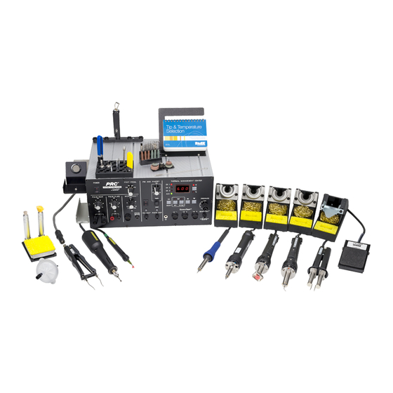
CAPABILITIES Your new PRC 2000 is the most advanced, self-contained rework and repair system ever created for the service bench or manual production workstation. The case's T-slot channels allow you to configure PRC 2000 accessories to suit individual operator preferences. The new style Tip & Tool Stands and Hot Cubbies can be mounted to the T-slot channels or set up freestanding (with the purchase of optional "Stand Alone"... -
Page 11: Primary Controls
PRIMARY CONTROLS In the upper left hand corner, you will find the master POWER Switch which controls all power to the unit. Just to the right of the POWER Switch is a 4-position FOOT PEDAL Selector Switch which directs the action of the foot pedal connected to the FOOT PEDAL Receptacle (rear panel). -
Page 12: Pulse Heat
PULSE HEAT At the lower left of the control panel you will find the PULSE HEAT section of the PRC 2000. The two AC jacks are for connecting the Universal Power Cord to the PRC 2000 system. The cord will accept several quick connect/disconnect handpieces including the LapFlo, ResisTweez, ConducTweez (optional) and StripTweez (optional) which can be changed within 2 seconds. -
Page 13: Pulse Plate
(EOS) discharge damage to sensitive components. PACE ThermoBand tips, which fit the ResisTweez, are specially insulated to keep leakage below 2mV. The control knob located above the AC terminals (PULSE HEAT Output Control) controls the amount of energy delivered to the handpieces. -
Page 14: Microchine
The MICROCHINE represents the latest PACE development in hand machining for the circuit board rework and repair. The self-contained motor handpiece connects to the PRC 2000 via a special connector. The motor unit can be actuated by a fingertip control switch or the foot pedal. A tachometer feedback loop between the motor and controller keeps the speed that you select constant as the load on the motor changes. -
Page 15: Pik And Paste
The paste dispensing system occupies the right half of the PIK AND PASTE section of the PRC 2000 and can dispense a variety of solder cremes, fluxes, potting compounds and adhesives. The Paste Dispense air hose comes equipped to accept standard 10cc material barrels. -
Page 16: Thermal Management Center
The THERMAL MANAGEMENT CENTER occupying the right 1/3 of the front panel is the heart of your PRC 2000 system. This microprocessor based multi-channel center can control up to six devices at one time. To the left of the Digital Readout are the three LEDs which indicate the "Current Channel" (i.e., the channel whose temperature information can be adjusted and is displayed on the Digital Readout (CH 1, CH 2 and CH 3)). - Page 17 Figure 6. Thermal Management Center...
-
Page 18: Parts Identification
PARTS IDENTIFICATION SYSTEM 1. POWER SWITCH - Turns system ON (“1”) and OFF (“0”); controls input power to the system. 2. FOOT PEDAL SELECTOR SWITCH - Control knob provides foot pedal connection to Pik and Paste (PD), MicroChine (MC), Pulse Plate (PP) or Pulse Heat (PH) features. POWER SWITCH Figure 8. -
Page 19: Front Panel Features
FRONT PANEL FEATURES PULSE HEAT 3. PULSE HEAT OUTPUTS - Low voltage AC power outputs for Low Voltage, Pulse Heat handpieces. 4. PULSE HEAT OUTPUT CONTROL - Controls low voltage AC power at PULSE HEAT Outputs. 5. PULSE HEAT LED - Illuminates Green in color when power is applied (by foot pedal through FOOT PEDAL Selector Switch) to the PULSE HEAT Outputs. - Page 20 PULSE PLATE 6. PULSE PLATE OUTPUTS - DC power connections for PACE SwaPlater plating system. 7. PULSE PLATE OUTPUT CONTROL - Controls DC power at PULSE PLATE Outputs. 8. PULSE PLATE LED - Illuminates Green to indicate when power is applied (upon foot pedal actuation) at the PULSE PLATE Outputs.
- Page 21 MICROCHINE 9. MICROCHINE POWER RECEPTACLE - Provides power, speed control, tip ground and finger switch connection for the MicroChine handpiece. 10. VARIABLE SPEED CONTROL - Controls motor speed (2,500 - 10,000 RPMs) of MicroChine handpiece. 11. PROBE BRAKE RECEPTACLE - Provides Probe Brake connection for the MicroChine Probe Brake feature.
- Page 22 PIK AND PASTE 13. PIK-VAC POWER SWITCH - Turns power “ON” (1) or “OFF” (0). Controls power to the Pik-Vac vacuum pump. 14. PIK-VAC LED - Illuminates Green to indicate Pik-Vac vacuum pump operation. 15. PIK-VAC PORT - Quick connect fitting which provides vacuum for Pik-Vac handpiece. 16.
- Page 23 Figure 12. Pik And Paste Section...
- Page 24 20. CH 1 POWER RECEPTACLE - Provides power, tip ground, sensing circuitry and finger switch connection from PRC 2000 system to handpiece connected to Channel 1 (CH 1). 21. CH 2 POWER RECEPTACLE - Provides power, tip ground, sensing circuitry and finger switch connection from PRC 2000 system to handpiece connected to Channel 2 (CH 2).
- Page 25 30. CH 2 LED - Illuminates when Channel 2 (CH 2) or Auxiliary Channel (AUX 2) is the Current Channel (i.e., the channel (with connected handpiece/tip or auxiliary accessory) whose temperature information is displayed on the Digital Readout). 31. CH 3 LED - Illuminates when Channel 3 (CH 3) or Auxiliary Channel (AUX 3) is the Current Channel (i.e., the channel (with connected handpiece/tip or auxiliary accessory) whose temperature information is displayed on the Digital Readout).
- Page 26 39. SCROLL DOWN KEY - Decreases the Set Tip Temperature (in TIP SET Mode) and Tip Temperature Offset Constant (in TIP OFFSET Mode) in one, then ten degree increments. Also used in “CAL” (Calibration) Mode. 40. EARTH GROUND RECEPTACLE - Provides positive earth ground to which a ground cable can be connected from the workpiece or work surface as part of a static control program.
-
Page 27: Rear Panel
REAR PANEL 41. AC POWER RECEPTACLE/FUSE HOLDER - Receptacle for providing power to the PRC 2000 system from AC outlet through power cord. Also location of fuse (F1) which protects the system from overcurrent conditions. 42. FUSE F1 - Provides overload protection for PRC 2000 system. - Page 28 49. TIP & TEMPERATURE SELECTION SYSTEM CHART HOLDER (NOT SHOWN) - Holds PACE’s Tip & Temperature Selection System charts (booklet) which enable the operator to accurately set and display the true, correct operating tip temperature for any handpiece/tip configuration connected to CH 1, CH 2 or CH 3.
- Page 29 HEADING GUIDELINES PACE adheres to the following Heading Guidelines (based on OSHA guidelines) when listing special information or precautions to be taken. Especially important are all procedures and practices which, if not strictly observed, could result in injury or loss of life.
-
Page 30: Safety
PACE in the associated handpiece manual. 2. The front end (heater end) of the glass solder collection chamber in the PACE Sodr-X-Tractor is hot when the handpiece is in use. When removing the chamber for cleaning, grip the chamber at the rear seal. -
Page 31: Set-Up
SYSTEM Set up the PRC 2000 system using Figures 15 through 18 and the following steps. 1. Store the shipping container(s) in a convenient location. Reuse of these containers will prevent damage if you ship or store the system. 2. Place POWER Switch in the “OFF” or “0” position. - Page 32 Turn Locking Ring fully clockwise to lock in place. Figure 17. TMC Handpiece Connection 10. To avoid confusion among handpieces, PACE recommends the use of colored markers (P/N 6993- 0136 Cable Marker Kit) to identify the particular handpiece power cord and/or air hose. Attach any two like colored markers, one to each end of the handpiece power cord or air hose.
-
Page 33: Handpiece Vacuum/Pressure
HANDPIECE VACUUM/PRESSURE The SX-65A, SX-70 and TP-65 handpieces require the use of the SNAP-VAC (vacuum) Port and the TJ-70 handpiece requires the use of the Controllable PRESSURE Port on the THERMAL MANAGEMENT CENTER (TMC). There are two preferred methods for connection of the Air Hose. The advantages of each method are discussed in the paragraph below. - Page 34 Damage to or breakage of Vacuum Fitting or VisiFilter may occur. 6. Connect the handpiece power cord connector plug to one of the Power Receptacles. For convenience, PACE recommends the use of CH 3 for air handpieces. Figure 21. Handpiece Connection to TMC...
- Page 35 NOTE If more than one air-operated handpiece is connected to the THERMAL MANAGEMENT CENTER, insure that only one of the Air Hoses is connected to either the SNAP-VAC Port or Controllable PRESSURE Port. Attachment to both simultaneously will cause a deterioration in perfor- mance.
- Page 36 QUICK CONNECT METHOD CONT'D 3. Attach the ridged end of a male quick connect hose mount Fitting (P/N 1259-0087) to each end of the 54 inch (137cm) Air Hose. Push and turn hose onto each Fitting to seat properly. You may install metal hose clamps (enclosed with system) to further secure connections.
-
Page 37: Operation
INTRODUCTION The PRC 2000 systems are easy to operate and allow the operator the flexibility of using additional features as desired. The “Operation” portion of this manual will familiarize the user with the features of the system as received from the factory. -
Page 38: Thermal Management Center
THERMAL MANAGEMENT CENTER POWER UP 1. Insure that the system is properly prepared for operation. Refer to the “Set-Up” portion of this manual. The handpieces selected for your application should be connected to the unit. Connect any single air hose to either the SNAP-VAC Port or Controllable PRESSURE Port. -
Page 39: Operation
OPERATION CHANNEL LED OPERATION 4. The Channel LED (CH 1, CH 2 or CH 3) of the first Active Channel encountered by the system (Channel with connected handpiece) will be illuminated. This is the Current Channel. The Auxiliary LED (in conjunction with the appropriate Channel led (CH 1, CH 2 or CH 3) will illuminate if a Current Channel is an Auxiliary Channel (AUX 1, AUX 2 or AUX 3). - Page 40 DIGITAL READOUT OPERATION 7. The Digital Readout provides a 3 digit display of the Current Channel temperature information. The Digital Readout will show the Set Tip Temperature in the TIP SET Mode, Tip Offset Constants in TIP OFFSET Mode and the True (Operating Tip) Temperature in the Temperature Display Mode (normal operation).
- Page 41 NOTE Refer to “Tip & Temperature Selection” for a complete discussion of Tip Temperature Offset function. 10. Press the TIP OFFSET Key once to enter TIP OFFSET Mode. Immediately press and hold the Scroll Up Key. Observe the displayed TIP OFFSET CONSTANT increase, first in 1°...
- Page 42 PANEL CONTROLS CONT'D 13. Press the TIP SET Key once. This is TIP SET Mode. The TIP SET LED will flash and the Digital Readout will display the stored Set Tip Temperature for the Current Channel. As received from the factory, the Digital Readout will display “OFF”.
- Page 43 15. Press the TIP SET Key once again to enter the TIP SET Mode. Press and hold the Scroll Up Key. Observe as the displayed Set Tip Temperature increases first in 1°, then in 10° increments (°C or °F). Release the key when the Digital Readout reads 371°C (or 700°F).
- Page 44 PANEL CONTROLS CONT'D 18. Press the TIP SET Key once again and use the Scroll Up and Scroll Down Keys to enter your desired Set Tip Temperature. Immediately press the TIP SET Key to exit the TIP SET Mode. This enters the new Set Tip Temperature for the Current Channel into system memory.
- Page 45 21. Press the TIP SET Key. Notice that the system has retained the stored Set Tip Temperature in memory. Immediately press the TIP SET Key once again to exit TIP SET Mode. Figure 43. Store Set Tip Temperature 22. In order to prevent a handpiece/tip combination from inadvertently operating at an incorrect Tip Temperature, a safety feature incorporated within the system will prevent retention of a stored TIP...
- Page 46 PANEL CONTROLS CONT'D 24. Press the TIP OFFSET Key. Notice that the TIP OFFSET CONSTANT has now changed to the default value of “3” for °C (“6” for °F) and the TIP OFFSET LED turns off. Whenever a channel becomes inactive, the system memory automatically reverts to the default TIP OFFSET CONSTANT.
- Page 47 Tip, Handpiece and Temperature Options for your particular application. NOTE The PRC 2000 systems incorporate a “Dynamic Offset” feature which automatically adjusts the Tip Temperature Offset (based on the entered TIP OFFSET CONSTANT) for any Set Tip Temperature established by the operator.
- Page 48 PANEL CONTROLS CONT'D 24. Press the TIP OFFSET Key. Notice that the TIP OFFSET CONSTANT has now changed to the default value of “3” for °C (“6” for °F) and the TIP OFFSET LED turns off. Whenever a channel becomes inactive, the system memory automatically reverts to the default TIP OFFSET CONSTANT.
- Page 49 Tip, Handpiece and Temperature Options for your particular application. NOTE The PRC 2000 systems incorporate a “Dynamic Offset” feature which automatically adjusts the Tip Temperature Offset (based on the entered TIP OFFSET CONSTANT) for any Set Tip Temperature established by the operator.
-
Page 50: Tip & Temperature Selection
With any heating system, actual tip temperatures can differ greatly from temperature control settings. PACE’s unique “Tip & Temperature Selection System” allows you to select and maintain True Tip Temperatures for any size and type of tip and handpiece using the appropriate TIP OFFSET CONSTANT. -
Page 51: Password
PASSWORD A password feature of the THERMAL MANAGEMENT CENTER which, when activated, will prevent unauthorized alteration of stored System and Channel features listed in Table 1 "Factory Settings". If a password has been installed, "P - - " will appear on the Digital Readout to prevent the operator from changing any of the stored settings. - Page 52 INITIAL INSTALLATION OF A PASSWORD CONT'D 4. Release the TIP SET and the °F/°C Keys. The system is now in Password Mode. The Digital Readout will display “PS-” and only the three Channel LEDs plus the Auxiliary LED will remain illuminated signifying that the system does not have a Password installed.
- Page 53 6. Press any key except the TIP SET Key as the first key of the Password. 7. Press any key as the second key of the Password. Figure 54. First Key Not Tip Set Key 8. Press any key as the third (and last) key of the Password.
- Page 54 REMOVING A PASSWORD 1. Place the POWER Switch in the OFF (“0”) position. Figure 56. Power Off 2. Press and hold the TIP SET and the °F/°C Keys down. Figure 57. Enter Password Mode 3. Place POWER Switch in the ON (“1”) position. All the THERMAL MANAGEMENT CENTER LEDs will illuminate.
- Page 55 4. Release the TIP SET and the °F/°C Keys. The Digital Readout will now display “P - -” signifying that the system is now asking for the operator to enter the Password previously installed into the system's memory. Figure 59. Stored Password NOTE If “PS-”...
- Page 56 REMOVING A PASSWORD CONT'D 7. Press the third (and last) key of the Password. The Digital Readout will now display “PS-”. Figure 61. Digital Readout "P S -" 8. Press the TIP SET Key. Figure 62. Press Tip Set Key 9.
- Page 57 NOTE The password is not permanently removed until the Calibration Mode is exited normally by pressing the TIP OFFSET Key. If AC POWER is turned off while still in the Calibration Mode, the password will not be removed. CHANGING THE PASSWORD 1.
- Page 58 CHANGING THE PASSWORD CONT'D 3. Place Power Switch in the ON (“1”) position. All the THERMAL MANAGEMENT CENTER LEDs will illuminate. The Digital Readout will read “888” and change to read “1-0”. This number may be different on your unit. Figure 66.
- Page 59 6. Press the first key of the old Password. 7. Press the second key of the old Password. 8. Press the third (and last) key of the old Password. 9. The Digital Readout will now display “PS-”. Figure 69. Digital Readout "P S -" 10.
- Page 60 CHANGING THE PASSWORD CONT'D 11. Press any key as the second key of the new Password. 12. Press any key as the third (and last) key of the new Password. 13. The Calibration Mode has been automatically entered and the Digital Readout will now display “CAL”.
- Page 61 DANGER POTENTIAL SHOCK HAZARD The following steps are to be performed by qualified service personnel only. Removal of the rear panel exposes line voltage parts. Service personnel must insure that AC power cord is dis- connected when installing jumper wire (step #5) and disconnecting jumper wire (step #9).
-
Page 62: Calibration
CALIBRATION INTRODUCTION In Calibration (CAL) Mode, you can: 1. Change the Upper & Lower Temperature limits for each channel independently. 2. Set the default temperature scale to °F or °C as desired. 3. Enable or disable the Auto Temperature Setback/Power Down features. PROCEDURE 1. - Page 63 3. Place POWER Switch in the On (“1”) position. All of the system LEDS will light. The Digital Readout will read “888” and change to read “1-0”. This number may be different on your unit. Figure 78. Digital Readout "888" 4.
- Page 64 °F/°C READOUT DEFAULT 5. Press and release the TIP SET Key. The Digital Readout will display “S - X” (X = “-” or 1-9). Either the °F or °C LED will be on. This is the default temperature scale of the Digital Readout (e.g., if the °C LED is on, the Digital Readout will display Tip Temperatures and Tip Offset values in °C).
- Page 65 8. Press the TIP SET Key to store the °F/°C default and Automatic Temperature Setback time value in system memory. The Digital Readout will revert to “CAL” and only the CH 1 LED will remain lit. AUTOMATIC POWER DOWN Figure 83. Store Temperature Default 9.
-
Page 66: Temperature Limits
TEMPERATURE LIMITS NOTE All temperature limits are entered and stored in system memory in degrees F. LOWER TEMPERATURE LIMIT 11. Press and release the TIP SET Key. The Digital Readout will now display “L-X” (X = 1-9). This is the stored value of the Lower Temperature Limit in increments of 100°F. - Page 67 UPPER TEMPERATURE LIMIT 14. The Digital Readout now displays “H-X” (X = 1-9). This is the stored value of the upper temperature limit in increments of 100°F. Figure 87. Digital Readout "H - X" 15. Press Scroll Keys as necessary to increase (Scroll Up Key) or decrease (Scroll Down Key) the upper temperature limit.
-
Page 68: Temperature Setback
°C (“6” for °F). Figure 90. Digital Readout "OFF" TEMPERATURE SETBACK The PRC 2000 system is equipped with a Temperature Setback feature which, when enabled, will preserve tip life and reduce energy consumption. ACTIVATION There are two ways in which the system will enable the Temperature Setback feature. - Page 69 b) Press the Scroll Up Key. c) Release both keys. Figure 92. Temp. Setback Entry OPERATION 1. Temperature Setback for each channel is indicated by the following. a) The Current Channel LED will flash off once each 2 second period when that channel is in Temperature Setback Mode.
- Page 70 Listed below are 4 different ways to exit Temperature Setback Mode. 1. For any individual channel, perform the following operation. a) Press and release the CH SELECT Key until the Setback Channel becomes the Current Channel shown on the Digital Readout. Figure 93.
- Page 71 will change to the default value of “3” for °C (“6” for °F). To exit Temperature Setback Mode for all Channels, do either of the following. 3. Press and hold the Scroll Down Key; press the Scroll Up Key. Release both keys. This is the Figure 95.
-
Page 72: Automatic Power Down
AUTOMATIC POWER DOWN The Automatic Power Down feature of the PRC 2000 system is a safety feature which removes power from all channels 90 minutes after all Active Channels have entered the Temperature Setback Mode. This feature is not programmable and is automatically enabled when all Active Channels are in the Temperature Setback Mode. -
Page 73: Digital Readout Message Codes
DIGITAL READOUT MESSAGE CODES Listed below are message codes and a description of each which may be displayed on the Digital Readout during the Calibration procedure. DISPLAY DESCRIPTION MESSAGE Refer to "CORRECTIVE MAINTENANCE" E-1,E-2,E-3 OR E-4 section. Indicates that system is in the Calibration Mode. Ready to accept new Upper Temperature Limit setpoint for this channel, where: X is limit in hundreds of degrees F. -
Page 75: Quick Reference - System Operation
The Quick Reference Charts shown may be used as a guide for quickly changing any particular parameter stored within the THERMAL MANAGEMENT CENTER of the PRC 2000 system. Locate the parameter you wish to change in the column marked “ACTION” and follow the simple instructions given under “Procedure”. - Page 76 ACTION PROCEDURE PRESS & HOLD POWER ON RELEASE AFTER 3 SECONDS E N T E R CALIBRATION (CAL) MODE DEFAULT PRESS ˚F TEMP SCALE KEYS OFFSET ˚C (°F/°C) ** (Press CHANGE LOWER PRESS TEMP LIMIT ** KEYS Twice) SELECT OFFSET CHANGE UPPER PRESS...
- Page 77 ACTION PROCEDURE M A N U A L PRESS & HOLD RELEASE AFTER 1 SECOND SETBACK ACTIVE C H A N N E L S E X I T PRESS & HOLD RELEASE AFTER 1 SECOND SETBACK A L L A C T I V E C H A N N E L S PRESS...
-
Page 78: Foot Pedal
FOOT PEDAL The foot pedal may be used with the PRC 2000 system in two different manners as described below. 1. FOOT PEDAL Receptacle - Connection of the foot pedal to this receptacle will allow the Pulse Heat (PH), Pulse Plate (PP), MicroChine (MC) and Pik &... -
Page 79: Pik And Paste
PIK AND PASTE Located in the middle of the front panel of the system power source, this portion of the PRC 2000 provides both a vacuum pick/placement capability (PIK) and a dispensing capability (PASTE) for use with a variety of solder cremes, high viscosity fluxes and adhesives. Refer to the “Capabilities” portion of this manual for a complete description of this feature. - Page 80 SET-UP CONT'D Air Hose 5. Slide the Hose Clamp over the free end of the Air Hose. Push clamp back 1 inch from the end of the Air Hose. Hose Clamp 6. Attach the free end of the Air Hose to the nipple on the Barrel Adapter (10 cc adapter is supplied).
- Page 81 OPERATION PACE recommends that the operator become familiar with the operation of the dispenser by first applying the material to a piece of paper or scrap PC board. Use this method to obtain the desired results for each dispensing material and application.
- Page 82 MATERIAL LOADING PACE recommends the use of prefilled barrels whenever practical to minimize any handling or safety precaution requirements. When loading is required, adhere to all precautions recommended by the material manufacturer. Refer to the Material Safety Data Sheet supplied with each material for information on important safety procedures and a listing of any toxic chemical elements.
- Page 83 Never install a clogged tip. The tip may be clogged with material used in a previous application. Install a new tip and discard after the required dispensing operation is completed. Listed below are the four tip sizes available from PACE. ITEM PART...
- Page 84 DISPENSING MATERIAL The operator may select the Continuous (CONT ) or TIMED Mode of operation. The CONT Mode allows the operator to dispense the material for as long as the foot pedal remains depressed. The TIMED/CONT Switch must be placed in the CONT position for use in this mode. This mode is recommended for use when dispensing a continuous bead of material.
- Page 85 4. Holding the barrel as shown (at a 45° angle to the work), rest the tip on a piece of paper and dispense a small amount of material. This initial dispensing will fill the tip with material. 5. Wipe any material residue from the end of tip.
-
Page 86: Vacuum Pick
DISPENSING SUGGESTIONS 1. Dispose of all tips and barrels after use. Always use new tips and barrels to prevent contamination, insure cleanliness and provide consistent, repeatable material deposition. 2. When dispensing different dot sizes, select a tip/time combination which dispenses small dots. These small dots may be dispensed in multiples to provide the deposition amount required. - Page 87 3. Attach one male quick connect hose Fitting (with attached Air Hose) to the rear of the Pik-Vac Handpiece. 4. Insert the other male quick connect hose Fitting (with attached Air Hose) into the PIK- VAC Port. 5. Attach the Metal Vacuum Tip to the end of the Pik-Vac Handpiece.
- Page 88 OPERATION CONT'D 4. Place the Vacuum Cup and/or the Metal Vacuum Tip gently onto the top surface of the Component body. Exercise caution to avoid bending of leads on fine pitch devices. 5. Place one finger over the Vacuum Control Port. Vacuum is now being applied to the Component body.
-
Page 89: Microchine
MICROCHINE The PACE MicroChine handpiece has a number of unique features which are not available in any other motorized, hand-held machining tool. The user is provided with a broad range of machining capabilities required in the repair, rework, modification, prototyping and manufacturing of printed circuit boards and electronic assemblies. - Page 90 SET-UP CONT'D 3. Adjust the MicroChine Variable Speed Control to the desired rotational speed. Speeds are available from 2500 to 10,000 R.P.M. On any task, start with a lower speed and increase it within your control. Figure 113. MC-65 Speed Control 4.
- Page 91 6. Set the FOOT PEDAL Selector Switch to the MicroChine (MC) position when foot pedal actuation is desired. In this mode either the finger switch on the handpiece or the foot pedal can actuate the MicroChine. Figure 116. Pedal Selector Switch 7.
-
Page 92: Probe Brake Operation
Brake lead may activate the electronic sensing circuitry, in continuity with the Probe Brake lead, in the system power source. In this case, PACE recommends the use of the PROBE BRAKE Receptacle to ground the workpiece. To prevent electrostatic build-up, this receptacle provides an impedance of 1,000 ohms to ground. -
Page 93: Pulse Plate
PULSE PLATE The PACE PRC 2000 system provides the DC electrical power, voltage level control power receptacles and LED indicator for controlled miniature plating. The LED indicator illuminates Green during normal operation and Red in short circuit or over current conditions. - Page 94 SET-UP CONT'D 3. Insure that the foot pedal is attached to the FOOT PEDAL Receptacle on the rear panel of the power source. Figure 121. Foot Pedal Connection 4. Place foot pedal in a convenient position on the floor beneath the workstation. 5.
- Page 95 Figure 122. Pulse Plate Set-Up...
-
Page 97: Pulse Heat
PULSE HEAT Located on the extreme left side of the PRC 2000 system, the PULSE HEAT section features a power output which provides controlled temperature ramp-up to solder reflow and rapid cool down. This controlled temperature ramp-up helps reduce the risk of thermal shock damage to components and substrates in combination with other measures such as preheating with the PACE HotSpot. - Page 98 SET-UP CONT'D 4. Attach the Universal Power Cord to the Universal Power Cord PULSE HEAT Outputs as shown. Figure 125. Universal Power Cord 5. Attach the proper tip for the task at hand, to the selected handpiece. Refer to the Pulse Heat Reference Guidelines for recommended tip/handpiece selection and PULSE HEAT Output Control settings.
-
Page 99: Operation
OPERATION 1. Set the FOOT PEDAL Selector Switch on the system front panel to the Pulse Heat (PH) position. Figure 127. Pedal Selector Switch 2. Press foot pedal and adjust the PULSE HEAT Output Control. Increase output level until selected tip heats to desired level. -
Page 100: Reference Guidelines
The PULSE HEAT Output Control reference guidelines listed in the table below are recommended by PACE as base reference parameters only. In each application, PULSE HEAT Output Control adjustments may be necessary. Start with the applicable setting listed below and increase output level in small increments until desired results are achieved. - Page 101 CAUTION For continuous use, the Output Level settings listed in Table 5 are the maximum recommended values. Exceeding these levels for extended periods may sometimes cause the handle to get hot. # LEADS COMPONENT OUTPUT OPERATION TYPE USED OUTLINE LEVEL SIZE REMOVAL &...
-
Page 103: Corrective Maintenance
VISIFILTER ELEMENT REPLACEMENT Follow the procedure listed below to replace the VisiFilter element when it becomes clogged or discolored. 1. Disconnect the handpiece air hose by gently turning and pulling the coupled Fittings. 2. Disconnect the Visifilter and hose assembly from the Power Source by gently turning and pulling the male Fitting inserted into the SNAP-VAC Port. -
Page 104: Handpieces
Operation and Maintenance Manual applicable to handpiece for instructions on troubleshooting that particular handpiece. The following "Heater Assembly Checkout Procedures" are applicable to all PACE SensaTemp handpieces except for the TT-65 ThermoTweez and DTP-80 Dual ThermoPik handpieces. Refer to either of the TT-65 manuals (P/N 5050-0300 or 5050-0336) for troubleshooting procedures pertinent to that handpiece. - Page 105 NOTE Perform the "Heater Assembly Checkout Procedures" shown below with the handpiece (and heater) at room temperature. If the handpiece is warm, resistance reading will be different from those shown in the table below. HEATER SYMPTOM CHECKOUT PROCEDURE CAUSE SOLUTION SPECIFICATIONS No heat Check resistance - Pin 2 to Pin 5.
-
Page 106: Power Source
Digital Readout is blank. Low AC line voltage. Check line voltage. Some functions work. Microprocessor pcb defect. Contact PACE Service Department. E-1 displayed on Digital All Channels are unplugged Plug handpiece into CH 1, CH 2 OR CH Readout. on Thermal Mgmt. Center. - Page 107 Power Receptacle on Thermal Thermal Management Center. Thermal Mgt. Center motor Management Center. pump activation. Defective motor pump. Contact PACE Service Department. Microprocessor pcb defect. Contact PACE Service Department. Keys on Thermal Key caps binding. Clean and/or adjust Key caps. Management Center don't Display pcb misaligned or Contact PACE Service Department.
- Page 108 Replace any clogged filters and clear (vacuum) or air pressure. clogged. all air hoses. Excessive motor pump noise. Defective motor pump. Contact PACE Service Department. Microprocessor pcb defect. Contact PACE Service Department. Digital Readout display is Shorted handpiece or Disconnect handpieces and erratic.
- Page 109 (& run in color. Management Center. MicroChine) until LED turns off. Multifunction pcb defect. Contact PACE Service Department. MicroChine Probe Brake Probe Brake test lead is Remove ground lead from pcb. activates prematurely. connected to or exciting a circuit having less than 500 ohms resistance to ground.
- Page 110 Status LED is illuminated Resume operation exerting less Yellow in color. pressure on handpiece. Defective handpiece. Replace handpiece. Multifunction pcb defective or Contact PACE Service Department. requires adjustment. Pik-Vac has insufficient "Low Pressure" output on Remove obstruction. vacuum. power source rear panel is obstructed.
-
Page 112: Replacement Parts
POWER SOURCE Listed below are the power source parts which may be ordered directly from PACE sales or your local authorized PACE distributor. For handpiece replacement parts, refer to the associated Operation and Maintenance Manual. To obtain power source parts other than those shown, contact your local PACE distributor or PACE Service Department directly at Telephone (301) 490-9860, Fax (301) 483-7030. -
Page 113: System Packaging
The tables on the following pages detail handpieces and accessory items available for use with the PRC 2000 systems. The handpieces and accessories supplied standard with each system version (e.g., Standard Version) are listed in the current revision of the PACE Price/Parts book. Contact your local authorized PACE distributor for additional information. -
Page 114: System Handpieces
SYSTEM HANDPIECES Item Number Description Part Number SensaTemp Handpieces SP-2A Sodr-Pen 6025-0014 SP-1A Sodr-Pen 6025-0013 SX-70 Sodr-X-Tractor 6010-0077 TJ-70 Mini ThermoJet 7023-0002 TP-65 ThermoPik 7024-0001 TT-65 ThermoTweez 7025-0001 Tip & Tool Stands for SensaTemp Handpieces SP Tip & Tool Stand (used with items #1 & 2 above) 6019-0043 SX Tip &... -
Page 115: System Accessories
Quick-Disconnect Insert (Male) 1259-0087 Quick-Disconnect Insert (Female) 1259-0086 Cable Marker Kit (Colored Tabs for hose/cord identification) 6993-0136 Wire Brush, 3/16" Daimeter 1127-0014 Wire Brush, 1/8" Daimeter 1127-0006 Tip Cleaner Kit 6993-0151 PACE Screwdriver 1100-0230 Service Manual 5050-0344 Table 10. System Accessories... -
Page 116: Sensatemp Handpieces
SENSATEMP HANDPIECES Listed below are available SensaTemp handpieces. These items may be ordered directly from PACE or through your local authorized PACE distributor. 1. SP-2A Sodr-Pen Soldering Iron - P/N 6025-0014 - Provides a wide range of SMD and thru-hole installation and removal capability as well as unsurpassed thermal performance on heavy multilayer thru-hole assemblies at safe, lower working temperatures. - Page 117 Instructions Duplicate this form and submit comments on the copy. Keep the original to make future comments. Complete all requested information. Submit completed form to: PACE Incorporated Applications Engineering Fax: (301) 604 - 8782 9893 Brewers Court Laurel MD 20723-1990 U.S.A.
-
Page 118: Warranty
Warranty Information: LIMITED WARRANTY PACE warrants that this equipment will be free of defects in materials and workmanship for a period of one (1) year from the date of receipt by original purchaser. This warranty does not cover repair or replacement required as a result of misuse, mishandling or improper storage.