Table of Contents
Advertisement
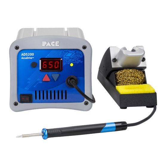
ADS200 Soldering System w/TD-200 Handpiece
Model
ADS200 w/Standard Tool Stand
ADS200 w/ISB Tool Stand
ADS200 w/Standard Tool Stand
ADS200 w/ ISB Tool Stand
Operation and Maintenance Manual for
Manual 5050-0589
Rev. Date 4/1232018
This manual applies to:
Firmware
Revision
1-2
1-2
1-2
1-2
Required Power
Part Number
120 VAC
120 VAC
230 VAC
230 VAC
8007-0578
8007-0579
8007-0580
8007-0581
Advertisement
Table of Contents

Related Manuals for Pace ADS200


Summary of Contents for Pace ADS200
- Page 1 Operation and Maintenance Manual for ADS200 Soldering System w/TD-200 Handpiece Manual 5050-0589 Rev. Date 4/1232018 This manual applies to: Firmware Model Required Power Part Number Revision ADS200 w/Standard Tool Stand 120 VAC 8007-0578 ADS200 w/ISB Tool Stand 120 VAC 8007-0579...
-
Page 2: Table Of Contents
Temperature Match Mode ........................9 Exiting Set-Up Mode..........................9 Corrective Maintenance ..........................9 Digital Display Message Codes ......................9 Power Source ............................10 Spare Parts .............................. 10 Optional AccuDrive® Blue Series Tip-Heater Cartridges ..............11 Service ..............................11 PACE LIMITED WARRANTY STATEMENT ................. 12... -
Page 3: General Information
General Information Introduction Thank you for purchasing the ADS200 Soldering System. This manual will provide you with the information necessary to properly set up, operate, and maintain your system. Please read this manual thoroughly before using the system. The systems featured in this guide are available in either 115 VAC or 230 VAC versions. All of these models incorporate AccuDrive®... -
Page 4: Power Supply Features
DO NOT touch the heater or the tip. Severe burns may result. 3. PACE Tip & Tool Stands are designed specifically for use with the associated handpiece and houses it in a manner that protects the user from accidental burns. Always store the handpiece in its holder. Be sure to place the handpiece in its holder after use and allow the Tip-Heater Cartridge to cool before storing. -
Page 5: System Set-Up
2. Place the Power Switch in the “OFF” or “0” position. Handpiece Connection The ADS200 is designed to work with the AccuDrive® TD-200 Tip-Heater Cartridge Iron and the AccuDrive® specific Blue Series Tip-Heater Cartridges, which have a blue end-cap. Caution: Using other handpieces or Tip- Heater Cartridges may result in damage to your ADS200 system or the attached handpieces and accessories. -
Page 6: System Power
Proper Tip-Heater Cartridge is installed in • handpiece. Power cord is connected to both an appropriate AC supply and the ADS200 unit. • 2. Turn the Power Switch On ("I"). 3. Press the Scroll Up ( ) Key. After a brief start-up sequence, the Set Temperature will be displayed. -
Page 7: Digital Led Display - Normal Operation
Default Factory Settings The ADS200 system comes equipped with a number of features, which may be adjusted by the user. Listed below are the default settings of each. To change and/or learn about any of these features, refer to the applicable part of the “Customizing Your System”... -
Page 8: Customizing Your System
Use the Scroll Up Key ( ) to change the default Temperature Scale. • Press and release the Program Key ( ) to proceed to the next step • ©2018 PACE Inc., Vass, North Carolina, All Rights Reserved Page 6... -
Page 9: Temperature Limits
Press and release the Program Key ( ) to proceed to the next step. • The allowable temperature range of the ADS200 is between 177° C (350° F) and 454° C (850° F). The Low Temperature Limit cannot be adjusted higher than the High Temperature Limit. These limits control how high or low the Set Temperature can be adjusted to during normal operation. -
Page 10: Autooff
In general, the higher the temperature, the more destructive to the iron plating. To significantly improve tip life, program 350° F or 177°C into the PS1 position. When the ADS200 is not in use, press the Program Key to initiate a “Manual Temperature SetBack” and when ready to use the station again push the Program Key twice to re-establish the operating temperature that is in the PS2 position. -
Page 11: Setback Temperature
Receptacle or is faulty, or the Tip-Heater Cartridge is not properly inserted or faulty. “Over Current Error” The Tip-Heater Cartridge circuit is shorted or the handpiece has failed. Replace the Tip-Heater Cartridge. ©2018 PACE Inc., Vass, North Carolina, All Rights Reserved Page 9... -
Page 12: Power Source
Contact PACE Spare Parts Description PACE Part Number Fuse 1.25 Amp, Time Lag (for 115V) 1159-0251-P5 Fuse 0.63 Amp, Time Lag (for 230V) 1159-0214-P5 Optional under shelf mounting bracket 1321-0609-P1 ©2018 PACE Inc., Vass, North Carolina, All Rights Reserved Page 10... -
Page 13: Optional Accudrive® Blue Series Tip-Heater Cartridges
For delicate micro-soldering to challenging, high thermal mass applications Ultra-Performance Tips Optimized tip geometries and increased thermal pipeline deliver maximum heat throughput Service Please contact PACE or your local distributor for service and repair. ©2018 PACE Inc., Vass, North Carolina, All Rights Reserved Page 11... -
Page 14: Pace Limited Warranty Statement
(6) months. Monitors, computers and other brand equipment supplied but not manufactured by PACE are covered under their respective manufacturer’s warranty in lieu of this Warranty.