Sign In
Upload
Manuals
Brands
Siemens Manuals
Recording Equipment
Albatros2 RVA78.690
Siemens Albatros2 RVA78.690 Manuals
Manuals and User Guides for Siemens Albatros2 RVA78.690. We have
4
Siemens Albatros2 RVA78.690 manuals available for free PDF download: User Manual, Technical Manual
Siemens Albatros2 RVA78.690 User Manual (258 pages)
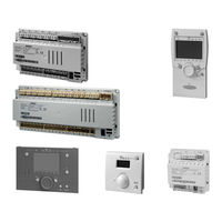
AVS75, AVS37, QAA75, QAA78, QAA55 Series Heat pump controller
Brand:
Siemens
| Category:
Controller
| Size: 5.44 MB
Table of Contents
3
Table of Contents
2
Ce1U2355En
3
Table of Contents
10
Overview
11
1.1 Product Range Overview
11
Topology
12
Operation Options
13
Safety Notes
13
Notes On Product Liability
14
Mounting and Installation
14
Regulations
14
Heat Pump Controller RVS
14
Engineering
14
Mounting Method
15
Dimensions and Drilling Plan
16
Connection Terminals RVS61.843
16
Terminal Markings:rvs41.813
19
Connection Terminals of RVS41.813
19
Terminal Markings RVS41.813
21
Extension Module AVS75.390
21
Dimensions and Drilling Plan
21
3.3.1 Connection Terminals AVS75.390
22
Terminal Markings
22
Assignment of Terminals
23
Operator Unit AVS37.294
23
Mounting Method
24
3.5 Operator Unit AVS37.390
24
Connections
24
Dimensions
25
3.6 Room Unit QAA55
25
Engineering
25
Dimensions and Drilling Plan
26
Room Unit QAA75
26
Engineering
27
Dimensions and Drilling Plan
28
RF Components
28
RF Module AVS71.390
29
Room Unit QAA78.610
29
Engineering
29
Mounting with the Base
30
Connections / Power Supply
30
Radio Connection
31
Dimensions and Drilling Plan
32
Wireless Outside Sensor AVS13.399
32
Mounting Method
33
Radio Connection
33
Dimensions and Drilling Plan
34
RF Repeater AVS14.390
34
Mounting Method
34
Connections
34
Radio Connection
34
Dimensions and Drilling Plan
35
Checking the RF Components
36
Commissioning
36
4.1 Heat Pump Controller
37
Handling
37
Qaa75
37
Operation
37
Operating Elements
38
Display Choices
38
Selecting Pace Heating Mode
39
Selecting Cooling Mode
39
Selecting DHW Heating Mode
40
Adjusting the Room Temperature Setpoint
40
Occupancy Button
40
Displaying Information
42
Manual Defrost of HP / Reset
43
Programming the QAA75
43
Setting Principle
43
Example "Setting the Time of Day
44
User Levels
45
Setting Structure "End User
45
Setting Structure "Heating Engineer
46
Overview of the Settings
54
Table of Contents
77
5.2 Qaa55
77
Operation
77
Operating Elements
77
Display Choices
77
Selecting Pace Heating Mode
78
Indication of Cooling Mode
78
Adjusting the Room Temperature Setpoint
78
Occupancy Button
79
Programming
80
Operator Section
80
Operation and Display
82
Heating Circuit Assignment
82
Room Sensor
83
Device Data
80
The Settings in Detail
80
Time of Day and Date
83
Radio Links
83
Binding
83
List of RF Devices
84
Holidays
84
Time Programs
84
Switching Points
84
Standard Program
85
Heating Circuits
85
Operating Mode
85
Setpoints
86
Heating Curve
87
ECO Functions
88
Flow Temperature Setpoint Limits
89
Room Influence
90
Room Temperature Limitation
90
Boost Heating
91
Quick Setback
91
Optimum Start / Stop Control
92
Raising the Reduced Setpoint
92
Overtemp Prot Pump Heating Circuit
93
Mixing Valve Control
93
Floor Curing Function
96
Excess Heat Draw
96
Buffer Storage Tank / Primary Controller
97
Remote Control
97
Frost Protection for the Heating Circuit
97
Cooling Circuit 1
98
Operating Mode
98
Setpoints
98
Release
99
Cooling Curve
99
Eco
100
Summer Compensation
100
Flow Temperature Setpoint Limits
101
Room Influence
102
Room Temperature Limitation
102
Mixing Valve Control
103
Dewpoint Monitoring
104
Buffer Storage Tank / Primary Controller
104
Remote Control
105
Frost Protection for the Heating Circuit
105
Domestic Hot Water
105
Overview
105
Setpoints
106
Release
107
Charging Priority
107
Legionella Function
109
Circulating Pump
109
Hx Pumps
109
Overview
110
Hx Pumps
111
6.10 Swimming Pool
111
Overview
111
Setpoints
111
Priority
112
Plant Hydraulics
112
6.11 Primary Controller / System Pump
112
Overview
112
6.12 Heat Pump
113
Function Diagrams
114
Condenser Pump
115
Source Pump
116
Compressor Control in Plants Without Buffer or Combi Storage Tank
117
Overview of Setpoint and Control Sensor Selection
118
Compressor Control in Plants with Buffer or Combi Storage Tank
119
Compressor Settings
122
Compressor 2
124
Electric Immersion Heater in the Flow
126
Heat Pump Protection During DHW Charging
127
General Parameters
128
Heat Pump Protection During DHW Charging
130
Defrost Function for Air-To-Water Heat Pumps
131
Automatic Defrost Function
134
Frost Protection for the Heat Pump
134
Cooling
136
During Compressor Operation
137
Sensor Calibration
138
Readj Hp Return Sensor
138
Readj Status
139
6.13 Energy Meter
141
Heat Volume Meter
141
Pulse Count Heat
141
Pulse Unit Heat
141
Pulse Unit Heat Numer
141
Pulse Unit Heat Denom
142
Flow Heating
143
Energy Counter Electricity/Natural Gas
143
Pulse Count Energy
143
Pulse Unit Energy
143
Pulse Value Energy Numer
143
Pulse Value Energy Denom
144
Counter/Performance Factor
144
Mean Gas Energy Content
144
Electric Source Output
144
Heat Delivered
145
Fixed Day Storage (Yearly Performance Factor)
145
Energy Brought in
148
6.14 Cascade
148
Control
148
Heat Source Sequence
149
Electric Immersion Heaters in the Cascade
150
Supplementary Source (Only RVS41
150
Operating Mode
150
Overtemperature Protection
150
Control
152
6.16 Solar
152
Overview
152
Charging Controller (Dt)
153
Priority
154
Start Function
154
Collector Frost Protection
154
Overtemperature Protection for the Collector
155
Medium's Evaporation Temperature
155
Speed Control
155
Yield Measurement
156
6.17 Buffer Storage Tank
156
Overview
156
Forced Charging
157
Automatic Locks
159
Stratification Protection
159
Overtemperature Protection
160
Recooling
160
Electric Immersion Heater
161
Solar Integration
161
6.18 DHW Storage Tank
161
Abortion of DHW Charging
161
Charging Control
162
Overtemperature Protection
163
Recooling
163
Electric Immersion Heater
164
Excess Heat Draw
165
Plant Hydraulics
165
Speed-Controlled Pump
167
Transfer
167
Instantaneous DHW Heater (Only RVS61.843)
167
Overview
168
6.20 Configuration
168
Setpoints
168
Speed-Controlled Pump
168
Mixing Valve Control
168
Procedure
169
Preselection of Plant Diagram
169
Manual Setting / Adjustment of Partial Diagrams
169
Heating/Cooling Circuit 1
170
Heating Circuit 2
171
DHW Controlling Element Q3
171
Separate DHW Circuit
172
Heat Pump
173
Solar
174
Buffer Storage Tank
174
Output Relay QX
179
Function Output Qx4-Mod
179
Sensor Input BX1, BX2, BX3, BX4, BX5
180
Input H1, H3
186
Input EX1, EX2, EX3, EX4, EX5, EX6, EX7
188
Mixing Group
189
Extension Module
189
Frost Protection On the Extension Module
190
QX Extension Module
191
BX Extension Module
191
H2 Extension Module
192
10V Output UX
193
Types of Sensor / Readjustment
193
Building and Room Model
194
Frost Protection for the Plant
194
Air Dehumidifier
195
Sensors
195
Parameters
195
Plant Diagram
198
Device Data
198
6.21 Lpb
198
Address / Power Supply
199
Central Functions
201
Clock
201
6.22 Errors
201
Reset
202
Error Message Functions
202
Error History
202
Error List
206
6.23 Service / Special Operation
206
Maintenance Functions
208
Other Maintenance Messages
208
Economy Mode
209
Emergency Operation
209
Simulation
210
Manual Defrost
210
Definition of Responsibilities
210
6.24 Input / Output Test
210
Output Test Relays
211
Output Test UX
211
Input Test Sensors
212
Input Test E
213
6.25 State of Plant
213
Messages
217
History
217
6.27 Diagnostics Heat Source
217
Brine-To-Water Heat Pump
218
Setpoints and Actual Values
219
Time / Start Counter
219
Heat Pump Air
220
Solar
217
Diagnostics Cascade
217
Priority/State
221
6.28 Diagnostics Consumers
221
Outside Temperature
221
Room
222
Heating Circuits 1, 2, P
222
Cooling Circuit 1
223
Domestic Hot Water
223
Swimming Pool
223
Primary Controller
223
Common Flow
223
Buffer Storage Tank
224
Input H1
224
Water Pressure
224
States Multifunctional Relays
224
States of Relays Extension Modules 1 and 2
225
6.29 Pump Kick
226
Basic Diagrams
241
Legend (Catalog of Plant Diagrams and Extra Functions)
226
Plant Diagrams
242
Basic Units RVS61.843 and RVS41.813
242
Technical Data
243
Extension Module AVS75.390
244
Operator and Room Unit AVS37
245
RF Module AVS71.390
246
8.5 Wireless Outside Sensor AVS13.399
247
8.6 RF Repeater AVS14.390
248
8.7 Sensor Characteristics
248
8.7.1 NTC 1K
249
8.7.2 NTC 10K
249
Pt1000
Advertisement
Siemens Albatros2 RVA78.690 User Manual (239 pages)
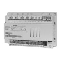
Boiler controller
Brand:
Siemens
| Category:
Controller
| Size: 2.48 MB
Table of Contents
3
Table of Contents
5
1 Summary
6
Type Summary
6
Topology
7
The Communication Choices in Detail
8
2 Safety Notes
8
Notes On Product Liability
8
3 Mounting and Installation
8
Regulations
8
Basic Units RVS43.345
10
Connection Terminals RVS43.345
13
Extension Module AVS75.370
14
Connection Terminals AVS75.370
16
Extension Module Avs75.39X
17
Connection Terminals AVS75.390
19
Connection Terminals AVS75.391
21
4 Commissioning
21
Basic Unit RVS43.345
22
5 Overview of Settings
51
6 The Settings in Detail
51
Time Programs
51
Holidays
52
Heating Circuits
70
Cooling Circuit
79
Dhw
84
Consumer Circuits and Swimming Pool Circuit
86
Swimming Pool
88
Primary Controller/System Pump
91
Boiler
103
Cascade
108
Supplementary Source
113
Solar
120
6.13 Solid Fuel Boiler
124
Buffer Storage Tank
133
DHW Storage Tank
146
Instantaneous DHW Heater
149
Configuration
183
Lpb
187
Fault
188
Maintenance/Special Operation
192
Configuring the Extension Modules
197
Input/Output Test
198
State
203
6.24 Diagnostics Cascade
204
Diagnostics Heat Source
205
Diagnostics Consumers
206
Pump and Valve Kick
208
List of Displays
208
6.28.1 Error Codes
210
6.28.2 Maintenance Code
210
6.28.3 Special Operation Code
211
7 Plant Diagrams
212
Basic Diagrams
212
Basic Diagram RVS43.345
213
Source Variants
214
Extra Functions in General
220
Auxiliary Functions with Mixer Group or Extension Module AVS75.3XX
225
8 Technical Data
225
Basic Unit RVS43.345
227
Extension Module AVS75.370
229
Extension Module Avs75.39X
230
Sensor Characteristics
230
NTC 1 K
231
NTC 10 K
231
Pt1000
232
Index
Siemens Albatros2 RVA78.690 Technical Manual (101 pages)
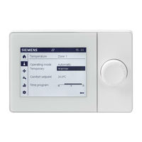
Graphical User Interface UI400
Brand:
Siemens
| Category:
Recording Equipment
| Size: 1.64 MB
Table of Contents
2
Legal Note
7
Overview
9
Design of QAA74 Room Units
10
Design AVS74 Operator Units
11
Engineering Use
14
Operator Units AVS74
19
Mount and Connect
20
Mounting QAA74 Room Unit
25
Surface Mount Cable Routing
28
Uninstall QAA74
29
Switch On Room Unit QAA74
30
Mount AVS74 Operator Unit
31
Front Side Installation (AVS74.261)
32
Rear Side Installation (AVS74.661, AVS74.761)
34
Switch-On Operator Unit AVS74
35
USB Connection, Unlock Button
36
Operation
41
Plant Operation, Quick Access
42
Operate Start
44
Operating Heating/Cooling
50
Operate Ventilation
53
Operate Hot Water
56
Evaluate Plant and Set
57
Evaluate and Operate Info
58
Operate Messages (Errors, Maintenance Messages)
61
Plant Information
63
Energy Consumption
64
Operating Service/Setting
65
Regional Settings
66
Operate Special Functions
68
Set Important Plant Parameters
69
Login to Expert View
71
Commission Plant Using the Commissioning Wizard
73
Analyze Plant and Set
74
Test Plant, Diagnostics
75
Example Input/Output Test
77
Set Plant and Troubleshoot
78
Complete Parameter List
80
Start Commissioning Wizards
81
Update Operator Unit
82
Technical Data
84
Avs74
85
Additional Information
86
Appendix
88
Settings in Detail
94
Special Operations
96
Manual Operation
99
Unlock Button On Boiler Management Units
Advertisement
Siemens Albatros2 RVA78.690 User Manual (64 pages)
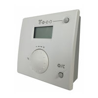
Solar compact controller
Brand:
Siemens
| Category:
Controller
| Size: 2 MB
Table of Contents
3
Table of Contents
4
2 Safety Notes
4
Notes On Product Liability
4
Summary
5
Mounting
5
3 Mounting and Installation
5
Planning
5
Regulations
10
Commission
11
Handling
11
Operating Elements
12
Display
13
Displaying Information
14
Programming
16
User Levels
18
Overview of the Settings
19
4131 F Temp Diff Off 4
23
6 The Settings in Detail
23
Operator Section
23
Time of Day and Date
24
Automatic Summer / Winter Recognition
24
Time Program
25
Domestic Hot Water
27
Solar
27
3812 F Charg Temp Min DHW St Tank
27
3813 O Temp Diff On Buffer
27
3814 O Temp Diff Off Buffer
27
3815 F Charging Temp Min Buffer
28
None ¦ DHW Storage Tank ¦ Buffer
28
3826 F Waiting Time Relative Prio
28
Waiting Time Relative Prio Min
28
Charging Time Relative Prio Min
28
Waiting Time Parallel Op Min
29
3831 F Min Run Time Collector Pump
29
3834 F Collector Start Funct Grad
29
3840 F Collector Frost Protection − − − − − − / -20
30
3850 F Collector Overtemp Prot
30
3860 F Evaporation Heat Carrier
30
3872 O Speed Xp
31
3881 F Antifreeze Concentration
31
3884 F Pump Capacity
31
None ¦ Kwh ¦ Liter
31
3888 F Pulse Value Yield Numer
31
3889 F Pulse Value Yield Denom
32
Solid Fuel Boiler
33
4130 F Temp Diff On
33
4131 F Temp Diff Off
34
Buffer Sensor
37
DHW Storage Tank
41
Configuration
47
Fault
48
Input/Output Test
49
State of Plant
51
Diagnostics Heat Source
51
Diagnostics of Consumer
52
Basic Diagrams
52
7 Plant Diagrams
55
Auxiliary Functions
60
Basic Units RVA78.690
60
8 Technical Data
61
Sensor Characteristics
62
Index
Share and save
Advertisement
Related Products
Siemens ASM 456
Siemens AVS74
Siemens SIMOTION ADI4
Siemens A80515
Siemens Albatros2 AVS75 Series
Siemens Albatros2 RVS46 Series
Siemens Albatros2 QAA75 Series
Siemens Albatros2 QAA78 Series
Siemens Albatros2 AVS37 Series
Siemens Albatros2 QAA55 Series
Siemens Categories
Controller
Control Unit
Switch
Measuring Instruments
Industrial Equipment
More Siemens Manuals
Login
Sign In
OR
Sign in with Facebook
Sign in with Google
Upload manual
Upload from disk
Upload from URL