Siemens Albatros2 RVA78.690 User Manual
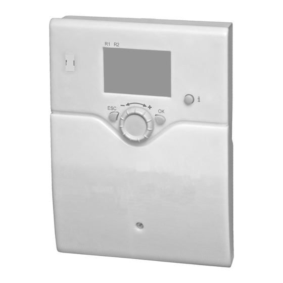
Solar compact controller
Hide thumbs
Also See for Albatros2 RVA78.690:
- User manual (221 pages) ,
- Technical manual (101 pages) ,
- User manual (258 pages)
Table of Contents
Advertisement
Quick Links
Download this manual
See also:
Technical Manual
Advertisement
Chapters
Table of Contents

Related Manuals for Siemens Albatros2 RVA78.690


Summary of Contents for Siemens Albatros2 RVA78.690
- Page 1 Albatros Solar compact controller RVA78.690 User manual CE1U2396en Building Technologies 18.08.2010...
- Page 2 Siemens Switzerland Ltd Industry Sector Building Technologies Division Gubelstrasse 22 6301 Zug Switzerland Tel. +41 41-724 24 24 © 2010 Siemens Switzerland Ltd www.siemens.com/sbt Subject to change 2 / 64 Siemens Solar compact controller CE1U2396en Building Technologies 18.08.2010...
-
Page 3: Table Of Contents
6.14 Diagnostics heat source................51 6.15 Diagnostics of consumer.................51 Plant diagrams ..................52 Basic diagrams..................52 Auxiliary functions ...................55 Technical data ..................60 Basic units RVA78.690................60 Sensor characteristics................61 Index ........................62 3 / 64 Siemens Solar compact controller CE1U2396en Building Technologies Table of contents 18.08.2010... -
Page 4: Summary
• Comply with all requirements specified in chapters "Handling" and "Technical data" when using the device. • Local regulations (for installation, etc.) must be complied with • Do not open the device. If not observed, warranty becomes void. 4 / 64 Siemens Solar compact controller CE1U2396en Building Technologies Summary... -
Page 5: Mounting And Installation
The device has two pre-punched connection openings on the back side and six on Prepare for mounting the under side. Break out the required connection openings prior to mounting. 5 / 64 Siemens Solar compact controller CE1U2396en Building Technologies Mounting and installation... - Page 6 DIN rail (1) and press on the lower part of the rails (2). Push the attachment fastening slide to (3) to the end position (4). 6 / 64 Siemens Solar compact controller CE1U2396en Building Technologies Mounting and installation 18.08.2010...
- Page 7 3.3.2 Dimensions and drilling plan Dimensions Measures in mm Drilling plan Measures in mm 7 / 64 Siemens Solar compact controller CE1U2396en Building Technologies Mounting and installation 18.08.2010...
- Page 8 3.3.3 Connection terminals A special connector is used for wiring; it is plugged into the plug on the controller. Plug assignment per image below: 8 / 64 Siemens Solar compact controller CE1U2396en Building Technologies Mounting and installation 18.08.2010...
- Page 9 AGP8S.03C/109 Protective earth Multifunctional output (Triac) Neutral conductor AGP8S.03C/109 Protective earth Collector pump 1 (Triac) Live AC 230 V basic unit AGP4S.03E/109 Protective earth Neutral conductor 9 / 64 Siemens Solar compact controller CE1U2396en Building Technologies Mounting and installation 18.08.2010...
-
Page 10: Commission
Operating state The current operating state can be checked on menu "State". Diagnosis For detailed diagnostics of the plant, check menus "Diagnostics heat generation" and "Diagnostics consumers". 10 / 64 Siemens Solar compact controller CE1U2396en Building Technologies Commission 18.08.2010... -
Page 11: Handling
The OK button enters the selected menu or setting lines. Confirm a set value with OK. The Escape button changes to the next highest level without saving values from the previous level. 11 / 64 Siemens Solar compact controller CE1U2396en Building Technologies Handling... -
Page 12: Display
It is a selection of the following temperature measured values: – Collector temp 1 – Collector temp 2 – DHW temp 2 – Buffer temp 2 12 / 64 Siemens Solar compact controller CE1U2396en Building Technologies Handling 18.08.2010... -
Page 13: Displaying Information
A plant fault is visualized in the basic display using the error icon Press the info button and read further information. R1 R2 A list of possible displays is available under "Display lists" on page 47. 13 / 64 Siemens Solar compact controller CE1U2396en Building Technologies Handling... -
Page 14: Programming
Press the OK button to confirm. The clock flashes on the display. R1 R2 Turn the setting knob to the correct time. Press the OK button to confirm. 14 / 64 Siemens Solar compact controller CE1U2396en Building Technologies Handling 18.08.2010... - Page 15 Returns to the basic display. R1 R2 Example of menu structure Time of day and date Year Operator section Date Time program Time of day 00:00 - 23:59 15 / 64 Siemens Solar compact controller CE1U2396en Building Technologies Handling 18.08.2010...
-
Page 16: User Levels
Press OK. You are now at the required user R1 R2 level. To reach the OEM level, the relevant code must be entered. 16 / 64 Siemens Solar compact controller CE1U2396en Building Technologies Handling 18.08.2010... - Page 17 Domestic hot water Start of summertime Solar End of summertime Solid fuel boiler Buffer storage tank DHW storage tank Configuration Input/output test State Diagnostics heat generation Diagnostics consumers 17 / 64 Siemens Solar compact controller CE1U2396en Building Technologies Handling 18.08.2010...
-
Page 18: Overview Of The Settings
Legionella funct duration − − − / 10 1647 F Legionella funct circ pump Off ¦ On 1660 F Circulating pump release Switching programs 24h/day ¦ Switching program 18 / 64 Siemens Solar compact controller CE1U2396en Building Technologies Handling 18.08.2010... - Page 19 DHW sensor B3 ¦ DHW sensor B31 ¦ Buffer sensor B4 ¦ Buffer sensor B41 ¦ Flow temp setpoint ¦ Setpoint min 4140 O Pump overrun time Buffer storage tank 4700 E Nominal setpoint °C 19 / 64 Siemens Solar compact controller CE1U2396en Building Technologies Handling 18.08.2010...
- Page 20 K10 ¦ Storage tank transfer pump ¦ Buffer return valve ¦ Solid fuel boiler pump ¦ El imm heater DHW K6 ¦ Heat request K27 ¦ Overtemperature protection K11 20 / 64 Siemens Solar compact controller CE1U2396en Building Technologies Handling 18.08.2010...
- Page 21 6804 F History 3 Error code 3 6806 F History 4 Error code 4 6808 F History 5 Error code 5 6820 O Reset history No ¦ Yes 21 / 64 Siemens Solar compact controller CE1U2396en Building Technologies Handling 18.08.2010...
- Page 22 DHW temp 2 °C 8835 I DHW circulation temp °C 8980 I Buffer temp 1 140.0 °C 8981 I Buffer setpoint °C 8982 I Buffer temp 2 °C 22 / 64 Siemens Solar compact controller CE1U2396en Building Technologies Handling 18.08.2010...
-
Page 23: The Settings In Detail
• Constant deactivation of programming. First, make the temporary deactivation, then go to operating line "Programming lock" (27) and deactivate the programming lock 23 / 64 Siemens Solar compact controller CE1U2396en Building Technologies The settings in detail... -
Page 24: Time Program
There is no need to charge the buffer in summer, since no heating requests are pending. Conversely, the electric immersion heating in the DHW may be enabled in summer whereas it is locked in winter. 24 / 64 Siemens Solar compact controller CE1U2396en Building Technologies The settings in detail 18.08.2010... -
Page 25: Domestic Hot Water
Nominal DHW setpoint TWWmax Nominal DHW setpoint maximum Nominal setpoint This operating line is used to limit the "Nominal setpoint" (1610) at the top. maximum 25 / 64 Siemens Solar compact controller CE1U2396en Building Technologies The settings in detail 18.08.2010... - Page 26 During the period of time the legionella function is carried out, there is a risk of scalding when opening the taps. 26 / 64 Siemens Solar compact controller CE1U2396en Building Technologies The settings in detail...
-
Page 27: Solar
TLmin Charging temp. min (DHW storage tank or buffer) Setting - - - in operating lines 3813 and 3814, adopts the general temperature differential of solar operating lines 3810 and 3811. 27 / 64 Siemens Solar compact controller CE1U2396en Building Technologies The settings in detail 18.08.2010... -
Page 28: None ¦ Dhw Storage Tank ¦ Buffer
Waiting time relative prio During the period of time set, the transfer of priority is delayed. This prevents relative priority from intervening too often. 28 / 64 Siemens Solar compact controller CE1U2396en Building Technologies The settings in detail... -
Page 29: 3831 F Min Run Time Collector Pump
• When the collector temperature returns to a level of 1 K above the frost protection temperature, the collector pump is deactivated again: TKol > TKolFrost + 1. 29 / 64 Siemens Solar compact controller CE1U2396en Building Technologies The settings in detail... -
Page 30: 3850 F Collector Overtemp Prot
3872 Speed Xp 3873 Speed Tn Pump speed The solar pump motor speed is limited by a minimum and maximum permitted min / max speed. 30 / 64 Siemens Solar compact controller CE1U2396en Building Technologies The settings in detail 18.08.2010... -
Page 31: 3881 F Antifreeze Concentration
Pulse measurement Each pulse received can be interpreted as a value (kWh or liters). The pulse value is defined using settings 3887-3889 (unit, counter and denominator). 31 / 64 Siemens Solar compact controller CE1U2396en Building Technologies The settings in detail... -
Page 32: Solid Fuel Boiler
The boiler pump will be put into operation only when the boiler temperature has reached a minimum temperature level, in addition to the required temperature differential. 32 / 64 Siemens Solar compact controller CE1U2396en Building Technologies The settings in detail... -
Page 33: 4130 F Temp Diff On
Pump overrun time If the boiler temperature drops below the minimum temperature differential or the minimum setpoint, the boiler pump keeps running for the parameterized overrun time. 33 / 64 Siemens Solar compact controller CE1U2396en Building Technologies The settings in detail... -
Page 34: Buffer Sensor
Sensor B4 is used for releasing the heat source. Sensor B41 is used generation lock. Auto heat gen lock SD The switching differential for generation lock can be set. 34 / 64 Siemens Solar compact controller CE1U2396en Building Technologies The settings in detail... - Page 35 The function "Recooling collector" cannot be switched off for recooling. Recooling collector When the collector is cold, the energy can be emitted to the environment via the collector’s surfaces. 35 / 64 Siemens Solar compact controller CE1U2396en Building Technologies The settings in detail...
- Page 36 (OL 4795), the return can be preheated by diverting it via the lower part of the storage tank. It is thus possible to preheat the return, for example. 36 / 64 Siemens Solar compact controller CE1U2396en Building Technologies The settings in detail 18.08.2010...
-
Page 37: Dhw Storage Tank
The buffer storage tank may receive no or too little energy during DHW charging – regardless of the hydraulic circuit. For this reason, it is often practical to set a time limit to DHW charging. 37 / 64 Siemens Solar compact controller CE1U2396en Building Technologies The settings in detail 18.08.2010... - Page 38 TSpMax 1°C TSpMax Storage tank temp max (5051) Actual value of the storage tank temperature Storage tank charging: 1 = on, 0 = off 38 / 64 Siemens Solar compact controller CE1U2396en Building Technologies The settings in detail 18.08.2010...
- Page 39 The electric immersion heater is always released, independent of time programs nd DHW release. Example: Time program For the electric immersion heater, the time program for the controller is taken into ccount. Example: 39 / 64 Siemens Solar compact controller CE1U2396en Building Technologies The settings in detail 18.08.2010...
- Page 40 Line no. Operating line 5130 Transfer strategy Always ¦ DHW release Transfer strategy Transfer is permitted either always or at the release times set (1620). 40 / 64 Siemens Solar compact controller CE1U2396en Building Technologies The settings in detail 18.08.2010...
-
Page 41: Configuration
OL 5931 Sensor input BX2 OL 5932 Sensor input BX3 - - - - - - - - - - - - OL = Operating line 41 / 64 Siemens Solar compact controller CE1U2396en Building Technologies The settings in detail 18.08.2010... - Page 42 Operation of the pump can be scheduled as required on operating page "DHW", operating line "Release circulating pump". Collector pump 2 Q16 When using a solar collector, a circulating pump for the collector circuit is required. 42 / 64 Siemens Solar compact controller CE1U2396en Building Technologies The settings in detail...
- Page 43 (6209) on the defined reference sensor (OL6208). It remains enabled until the temperature drops below the overheat protection temperature by the set switching differential (6210). 43 / 64 Siemens Solar compact controller CE1U2396en Building Technologies The settings in detail...
- Page 44 The low voltage signal is calculated and issued for collector pump Q5. Per output ZX1 The low voltage signal is calculated and issed for the pump connected to relay output ZX1 (Q4, Q16, K9, Q11 or Q10). 44 / 64 Siemens Solar compact controller CE1U2396en Building Technologies The settings in detail...
- Page 45 The parameters can be reset to their default values. Exempted from this are the following menus: Time and date, schedule as well as operating house and the various counters. 45 / 64 Siemens Solar compact controller CE1U2396en Building Technologies The settings in detail...
- Page 46 The software version indicated here represents the current controller version. Device hours run This indicates the total number of operating hours since the controller was first commissioned. 46 / 64 Siemens Solar compact controller CE1U2396en Building Technologies The settings in detail...
-
Page 47: Fault
6820 Reset history The error history with the last 5 errors, the associated actual values and setpoints and the relay output states will be deleted. 47 / 64 Siemens Solar compact controller CE1U2396en Building Technologies The settings in detail 18.08.2010... -
Page 48: Input/Output Test
Display of the sum total of pulses on input H1 since the pulse counter was comissioned. (Input H1 is set programmed for pulse counting and is not used by another function). 48 / 64 Siemens Solar compact controller CE1U2396en Building Technologies The settings in detail 18.08.2010... -
Page 49: State Of Plant
Overtemp prot active Max charging temp reached Max charging temp reached Charging DHW+buffer Charging DHW+buffer Charging DHW Charging DHW Charging buffer Charging buffer Radiation insufficient Radiation insufficient 49 / 64 Siemens Solar compact controller CE1U2396en Building Technologies The settings in detail 18.08.2010... - Page 50 Charged, max charging temp Charged, forced temp Charged, required temp Part charged, required temp Charged, min charging temp Charged Cold Cold No request No request 50 / 64 Siemens Solar compact controller CE1U2396en Building Technologies The settings in detail 18.08.2010...
-
Page 51: Diagnostics Heat Source
Various setpoints and actual values can be displayed for diagnostics (see Overview of settings as of page 18). Line no. Operating line 8703…8835 DHW diagnostics 8980…8982 Buffer storage tank diagnostics 51 / 64 Siemens Solar compact controller CE1U2396en Building Technologies The settings in detail 18.08.2010... -
Page 52: Plant Diagrams
Automatic settings: charging – Collector sensor B6 OL 5931 BX2: – Buffer storage tank sensor B41 – collector pump Q5 (OL 5840 Solar cntrl elem:) (charging pump) 52 / 64 Siemens Solar compact controller CE1U2396en Building Technologies Plant diagrams 18.08.2010... - Page 53 OL 5931 BX2: – Buffer storage tank sensor B41 – collector pump Q5 OL 5890 ZX1: – Solar controlling element buffer (OL 5840 Solar ctrl elem:) – Charging pump 53 / 64 Siemens Solar compact controller CE1U2396en Building Technologies Plant diagrams 18.08.2010...
- Page 54 Buffer storage tank sensor B41 OL 5932 BX3: – Collector sensor B61 – collector pump Q5 OL 5890 ZX1: – Collector pump 2 Q16 (OL 5840 Solar cntrl elem:) (charging pump) 54 / 64 Siemens Solar compact controller CE1U2396en Building Technologies Plant diagrams 18.08.2010...
-
Page 55: Auxiliary Functions
OL 4133 Comparative temperature: – DHW sensor B3 or – DHW sensor B31 or – Buffer storage tank sensor B4 or – Buffer storage tank sensor B41 55 / 64 Siemens Solar compact controller CE1U2396en Building Technologies Plant diagrams 18.08.2010... - Page 56 OL 5890 ZX1: – Storage tank transfer pump Q11 OL 5131 Comparative temperature transfer: – DHW sensor B3 – or B31 Optional settings: OL 5130 (Heat transfer strategy). 56 / 64 Siemens Solar compact controller CE1U2396en Building Technologies Plant diagrams 18.08.2010...
- Page 57 DHW storage tank Required settings: electric immersion heater OL 5890 ZX1: – Electric immersion heater DHW Optional settings: OL 5060 (operating mode). OL 5061 (release). OL 5062 (control). 57 / 64 Siemens Solar compact controller CE1U2396en Building Technologies Plant diagrams 18.08.2010...
- Page 58 OL 5890 ZX1: – alarm output K10 Overtemperature Required settings: protection OL 5890 ZX1: – Overtemperature protection K11 Heat requisition Required settings: OL 5890 ZX1: – Heat request K27 58 / 64 Siemens Solar compact controller CE1U2396en Building Technologies Plant diagrams 18.08.2010...
- Page 59 DHW circulation sensor Buffer storage tank temperature sensor Buffer storage tank temperature sensor Collector sensor Collector sensor 2 Solar flow sensor B63 Solar return sensor B63 Common return sensor 59 / 64 Siemens Solar compact controller CE1U2396en Building Technologies Plant diagrams 18.08.2010...
-
Page 60: Technical Data
-20…65°C Climatic conditions Transport to IEC721-3-2 class 2K3 temperature -25…70 °C Operation to IEC721-3-3 class 3K5 temperature 0...50 °C (noncondensing) Weight Without packaging RVA78.690: 530 g 60 / 64 Siemens Solar compact controller CE1U2396en Building Technologies Technical data 18.08.2010... -
Page 61: Sensor Characteristics
1,289.83 205.0 1,776.80 335.0 2,244.21 80.0 1,308.93 210.0 1,795.14 340.0 2,261.80 85.0 1,327.99 215.0 1,813.45 345.0 2,279.36 90.0 1,347.02 220.0 1,831.73 350.0 2,296.89 95.0 1,366.02 225.0 1,849.98 61 / 64 Siemens Solar compact controller CE1U2396en Building Technologies Technical data 18.08.2010... -
Page 62: Index
Comparative temperature ........33 Transfer ............. 40 K11................ 46 Configuration............41 Control boiler / burner ........... 33 Language.............. 23 Legionella function ..........26 Device data ............46 Lighting ..............23 62 / 64 Siemens Solar compact controller CE1U2396en Building Technologies Index 18.08.2010... - Page 63 Relay test.............. 48 Winter / Summer changeover .......24 Release..............26 Buffer storage tank ..........34 Yield measurement..........31 Request Heat..............46 Reset Error history............47 ZX1 ................42 Reset alarm relay..........47 63 / 64 Siemens Solar compact controller CE1U2396en Building Technologies Index 18.08.2010...
- Page 64 Siemens Switzerland Ltd Industry Sector Building Technologies Division Gubelstrasse 22 6301 Zug Switzerland Tel. +41 41-724 24 24 © 2010 Siemens Switzerland Ltd www.siemens.com/sbt Subject to change 64 / 64 Siemens Solar compact controller CE1U2396en Building Technologies 18.08.2010...
Need help?
Do you have a question about the Albatros2 RVA78.690 and is the answer not in the manual?
Questions and answers