Sign In
Upload
Manuals
Brands
Polaris Manuals
Offroad Vehicle
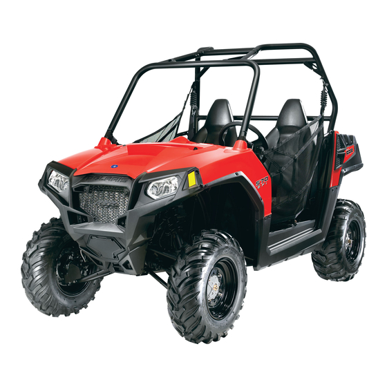
2012 RANGER RZR 570
Polaris 2012 RANGER RZR 570 Vehicle Manuals
Manuals and User Guides for Polaris 2012 RANGER RZR 570 Vehicle. We have
1
Polaris 2012 RANGER RZR 570 Vehicle manual available for free PDF download: Service Manual
Polaris 2012 RANGER RZR 570 Service Manual (403 pages)
Brand:
Polaris
| Category:
Offroad Vehicle
| Size: 19.63 MB
Table of Contents
Table of Contents
3
Chapter 1
6
Engine Designation Number
6
General Information
6
Model Identification
6
Model Information
6
Vehicle and Engine Serial Number Location
6
Vin Identification
6
Special Tools
7
2012 Ranger Rzr 570
7
2012 Ranger Rzr 570 Intl
7
2012 Ranger Rzr 570 Intl
10
Vehicle Information
7
Publication Numbers
7
Replacement Keys
7
Misc. Specifications and Charts
12
Conversion Table
12
Standard Bolt Torque Specification
13
Metric Bolt Torque Specification
13
Sae Tap / Drill Sizes
14
Metric Tap / Drill Sizes
14
Maintenance Chapter 2 Maintenance 2
15
Maintenance
15
Periodic Maintenance Chart
17
Break-In Period
17
Chapter 2
17
Maintenance Chart Key
17
Periodic Maintenance Overview
17
Pre-Ride - 25 Hour Maintenance Interval
18
50 - 500 Hour Maintenance Interval
19
Maintenance Quick Reference
20
Grease Lubrication Points
22
Lubricants / Service Products
23
General Vehicle Inspection and Maintenance
24
Pre-Ride / Daily Inspection
24
Frame, Nuts, Bolts, and Fasteners
24
Shift Cable Inspection / Adjustment
24
Fuel System and Air Intake
25
Fuel System
25
Fuel Line
25
Fuel Pump / Fuel Filters
26
Vent Lines
26
Throttle Pedal Inspection
26
Throttle Freeplay Adjustment
27
Engine and Pvt Intake Pre-Filter Service
27
Air Filter Service
28
Engine
30
Engine Oil Level
30
Engine Oil and Filter Service
30
Engine Breather Hose Inspection
32
Engine and Transmission Mounts
32
Compression Test Specification
32
Valve Clearance Inspection
32
Exhaust - Spark Arrestor
34
Transmission and Front Gearcase
35
Specification Chart
35
Transmission Lubrication
35
Front Gearcase Lubrication
37
Cooling System
39
Cooling System Exploded View
39
Cooling System Overview
40
Coolant Level Inspection
40
Cooling System Pressure Test
40
Coolant Strength / Type
41
Cooling System
41
Coolant Drain / Fill
41
Final Drive / Wheel and Tire
42
Wheel and Hub Torque Table
42
Wheel Removal
42
Wheel Installation
43
Tire Inspection
43
Tire Pressure
44
Drive Shaft Boot Inspection
44
Electrical and Ignition System
44
Battery Maintenance
44
Battery Removal
45
Battery Installation
45
Battery off Season Storage
45
Spark Plug Service
46
Engine to Frame Ground
47
Steering
47
Steering Inspection
47
Steering Wheel Freeplay
48
Tie Rod End / Wheel Hub Inspection
48
Wheel Toe Alignment Inspection
49
Wheel Toe Adjustment
49
Suspension
50
Spring Preload Adjustment
50
Brake System
51
Brake Fluid Inspection
51
Brake Pad / Disc Inspection
51
Brake Hose and Fitting Inspection
51
Parking Brake Cable Adjustment (Intl)
52
Parking Brake Pad Inspection (Intl)
52
Chapter 3 Engine / Cooling System
53
Engine / Cooling System
53
General Information
55
Engine Lubrication Specifications
55
Special Tools
55
Oil Pressure Test
56
Engine Oil Flow Chart
57
Engine Service Specifications
58
Engine Specifications - 1204286 Rzr570Ho-11
58
Engine Detail - Torque Values / Sequences / Assembly Notes
60
Main Engine Components - Torque Specification and Sequence
60
Crankcase / Timing Chain Guides / Oil Pickup / Regulator Valve
61
Cylinder / Oil Filter / Oil Pump / Breather
62
Camshafts / Cylinder Head / Flywheel / Idler Gears / Stator Cover
63
Spark Plugs / Starter / Throttle Body / Valve Cover
64
Piston / Crankshaft / Balance Shaft
65
Engine Cooling System
65
Cooling System Exploded View and Coolant Flow Diagram
66
Engine Cooling System
66
Cooling System Specifications
67
Cooling System Pressure Test
67
Pressure Cap Test
68
Radiator
68
Coolant Drain / Radiator Removal
69
Thermostat Replacement
70
Cooling System Bleeding Procedure
70
Water Pump Service
72
Water Pump Cover and Impeller Service
72
Water Pump Mechanical Seal / Oil Seal Replacement
73
Engine Service
78
Accessible Engine Components
78
Top-End Service (Engine in Chassis)
78
Engine Removal
79
Engine Installation
83
Engine Break-In Period
86
Engine Mounting and Torque Values
87
Engine Lubrication Specifications
87
Setting Tdc (Top-Dead-Center)
88
Engine Disassembly / Inspection - Top End
89
Valve Cover Removal
89
Camshaft Removal
89
Camshaft Sprocket Inspection
91
Camshaft / Camshaft Bore Inspection
91
Exhaust Camshaft Decompression Mechanism
93
Cam Chain and Guide Service
93
Cylinder Head Removal
94
Cylinder Head Disassembly
94
Cylinder Head Inspection
96
Cylinder Head Warp Inspection
96
Valve Inspection
96
Combustion Chamber Cleaning
97
Valve Seat Reconditioning
98
Cylinder Removal
100
Cylinder Inspection
100
Piston Removal
101
Piston-To-Cylinder Clearance
102
Piston / Rod Inspection
102
Piston Ring Installed Gap
103
Honing to Oversize
104
Cylinder Hone Selection / Honing Procedure
104
Cleaning the Cylinder after Honing
104
Engine Assembly - Top End
105
Piston Ring Installation
105
Piston / Connecting Rod Assembly
106
Cylinder Installation
107
Cylinder Head Assembly
108
Valve Sealing Test
109
Cylinder Head Installation
110
Valve Clearance Check / Adjustment
111
Intake Valve Lash - Shim Selection Matrix
113
Exhaust Valve Lash - Shim Selection Matrix
114
Camshaft Installation / Timing
115
Camshaft Timing - Quick Reference
118
Valve Cover Installation
119
Engine Disassembly / Inspection - Lower End
120
Crankcase Disassembly
120
Flywheel / Stator Housing Removal
120
Starter One-Way Clutch Inspection
121
Starter One-Way Clutch Installation
122
Flywheel Installation
123
Stator Removal
124
Stator / Stator Cover Installation
125
Oil Pump Removal
125
Oil Pump Assembly
127
Crankcase Breather Service
128
Crankcase Separation
128
Balance Shaft Removal / Inspection
129
Crankshaft Removal
130
Crankshaft Inspection
130
Pto Side Crankcase Bearing Service
131
Mag Side Crankcase Bearing Service
132
Oil Pickup Assembly Inspection
133
Oil Pressure Regulator (Bypass) Valve Inspection
133
Crankcase Inspection
133
Engine Assembly - Lower End
134
Crankcase Assembly - Pto Side
134
Balance Shaft Installation / Timing
136
Final Crankcase Assembly
136
Troubleshooting
138
Engine
138
Cooling System
139
Chapter 4 Electronic Fuel Injection
141
General Information
142
Service Notes
144
Efi System Exploded View
145
Efi System Component Locations
146
Electronic Fuel Injection
148
Fuel Tank
148
Efi Operation Overview
150
Initial Priming / Starting Procedure
150
Principal Components
150
Electronic Control Unit (Ecu)
151
Operation Overview
151
Ecu Service
151
Ecu Replacement
152
Temp / Manifold Absolutepressure Sensor (T-Map)
153
Operation Overview
153
T-Map Sensor Test
153
T-Map Sensor Replacement
153
Crankshaft Position Sensor (Cps)
154
Fuel Injectors
155
Operation Overview
155
Fuel Injector Troubleshooting
155
Fuel Injector Test
155
Cps Replacement
155
Fuel Injector Replacement
157
Fuel Pump
158
Operation Overview
158
Fuel Sender Test
159
Fuel Pump Test
159
Fuel Pump Replacement
161
Fuel Tank Removal
164
Fuel Tank Installation
167
Idle Air Control (Iac)
167
Throttle Position Sensor (Tps)
168
Operation Overview
168
Tps Resistance Tests
169
Tps Tester / Regulator
169
Tps Replacement
169
Engine Coolant Temperature Sensor (Ect)
171
Operation Overview
171
Ect Sensor Test
171
Ect Sensor Replacement
172
Ignition Coil
172
Efi Diagnostics
174
Efi Troubleshooting
177
Digital Wrench™ Operation
178
Diagnostic Software Version
178
Guided Diagnostic Available
178
Efi System Electrical Diagram
187
Body / Steering / Suspension Chapter 5 Body / Steering / Suspension
189
Body / Steering / Suspension
189
Torque Specifications
190
Special Tools
190
Cab Frame
191
Chapter 5 Assembly / Removal
191
Body Exploded Views
192
Side Safety Nets
192
Dash Instruments / Controls / Glovebox
193
Hood / Front Body Work
194
Front Bumper
195
Rear Bumper
195
Seat Assembly
196
Seat Belts / Mounting
196
Floor / Rocker Panels
197
Rear Cargo Box / Fenders
198
Chassis / Main Frame
199
Body Component Removal
200
Seats
200
Rear Service Panel
200
Front Bumper
200
Rear Bumper
200
Hood and Front Body Work
201
Rear Fender Flair Removal
202
Cargo Box Assembly Removal
202
Rocker Panels, Console and Floor
203
Steering Assembly
204
Exploded View
204
Steering Wheel Removal
205
Steering Shaft Bearing Replacement
205
Front A-Arms
206
Removal / Replacement
206
Exploded View
207
Ball Joint Service
208
Removal
208
Installation
209
Front Stabilizer Bar
209
Stabilizer Bar Linkage Removal
209
Stabilizer Bar Removal
209
Exploded View
211
Rear A-Arms
212
Removal
212
Installation
213
Exploded View
213
Rear Stabilizer Bar
214
Removal / Installation
214
Shocks / Springs / Fasteners
215
Exploded View
215
Shock Removal / Installation
215
Shock Replacement
216
Decal Replacement
216
Clutching Chapter 6 Clutching
217
Clutching
217
Special Tools and Supplies
218
Torque Specifications
218
Chapter 6 Pvt System Fastener Torques
218
Pvt System Overview
218
General Operation
218
Drive Clutch Operation
219
Driven Clutch Operation
219
Pvt Break-In (Drive Belt / Clutches)
219
Maintenance / Inspection
219
Overheating / Diagnosis
220
Pvt System Service
221
Pvt Covers and Ducting Components
221
Pvt Disassembly
221
Pvt Assembly
223
Drive Belt
224
Belt Removal
224
Belt Inspection
224
Belt Installation
225
Pvt Break-In (Drive Belt / Clutches)
225
Clutch Center Distance
226
Inspection
226
Adjustment
226
Drive Clutch Service
228
Drive Clutch Exploded View
228
Clutch Disassembly
229
Drive Clutch Spring Inspection
230
Shift Weight Inspection
230
Spider Removal
231
Roller, Pin, and Thrust Washer Inspection
232
Button to Tower Clearance Inspection
232
Bearing Inspection
232
Clutch Inspection
233
Bushing Service
234
Clutch Assembly
236
Driven Clutch Service
237
Exploded View
237
Clutch Disassembly / Inspection
237
Clutch Assembly
240
Troubleshooting
241
Final Drive Chapter 7 Final Drive
243
Final Drive
243
Special Tools
244
Torque Specifications
244
Chapter 7 Wheel and Hub Torque Table
244
Front Bearing Carrier
244
Bearing Carrier Inspection / Removal
244
Bearing Replacement
245
Bearing Carrier Installation
246
Front Drive Shaft
248
Drive Shaft Removal
248
Drive Shaft / CV Joint Handling Tips
249
Outer CV Joint / Boot Replacement
249
Inner Plunging Joint / Boot Replacement
251
Drive Shaft Installation
252
Propshaft Service
254
Removal / Installation
254
Transmission
255
Propshaft U-Joint Service
256
Disassembly
256
Assembly
257
Front Gearcase / Centralized Hilliard
258
Centralized Hilliard Exploded View
258
All Wheel Drive Operation
259
Awd Diagnosis
260
Gearcase Removal
261
Gearcase Disassembly / Inspection
262
Gearcase Assembly
265
Gearcase Installation
267
Rear Bearing Carrier
268
Bearing Carrier Inspection / Removal
268
Brakes
268
Bearing Replacement
269
Bearing Carrier Bushing Replacement
270
Bearing Carrier Installation
271
Rear Drive Shaft
272
Drive Shaft Removal
272
Outer CV Joint / Boot Replacement
274
Inner Plunging Joint / Boot Replacement
277
Drive Shaft Exploded View
279
Drive Shaft Installation
280
Wheel Hub
280
Wheel Hubs
282
Front Hub Exploded View
282
Rear Hub Exploded View
282
Chapter 8 Transmission
283
Lubrication
284
Special Tools
284
Specifications
284
Torque Specifications
284
Transmission Mounting and Torque Values
284
Shift Lever
285
Removal
285
Installation
285
Shift Cable
286
Inspection
286
Adjustment
286
Transmission Service
287
Transmission Removal
287
Transmission Installation
290
Transmission Disassembly
294
Gear / Shaft / Bearing Inspection
300
Snorkel Gear Backlash Procedure
301
Transmission Assembly
303
Electrical
308
Transmission Disassembly
309
Planetary Differential Disassembly
314
Planetary Differential Bushing Replacement
314
Planetary Differential Assembly
317
Gear / Shaft / Bearing Inspection
317
Snorkel Gear Backlash Procedure
318
Transmission Assembly
320
Troubleshooting
325
Troubleshooting Checklist
325
Transmission Exploded View
326
Transmission Exploded View (Intl)
328
Brakes Chapter 9 Brakes
331
Transmission Service (Intl)
308
Differential Operation
308
Chapter 9
332
General Specifications
332
Special Tools
332
Torque Specifications
332
Brake Noise Troubleshooting
333
Brake System Service Notes
333
Hydraulic Brake System Operation
334
Brake System Exploded View
335
Brake Pedal Lever
336
Pedal Removal
336
Pedal Installation
336
Master Cylinder
336
Brake Bleeding / Fluid Change
337
Parking Brake (Intl Model)
338
Parking Brake Caliper Service (Intl Model)
340
Parking Brake Disc (Intl Model)
342
Front Brake Pads
343
Pad Removal
343
Pad Inspection
344
Pad Assembly / Installation
344
Brake Burnishing Procedure
345
Front Caliper Service
346
Caliper Exploded View
346
Caliper Removal
346
Caliper Disassembly
347
Caliper Inspection
348
Caliper Assembly
348
Caliper Installation
349
Front Brake Disc
350
Disc Runout
350
Disc Inspection
350
Disc Replacement
351
Rear Brake Pads
352
Pad Removal
352
Pad Inspection
353
Pad Assembly / Installation
353
Brake Burnishing Procedure
354
Rear Caliper Service
355
Caliper Exploded View
355
Caliper Removal
355
Caliper Disassembly
356
Caliper Inspection
357
Caliper Assembly
357
Caliper Installation
358
Rear Brake Disc
358
Disc Inspection
358
Disc Replacement
359
Troubleshooting
360
Pedal Vibration
360
Brakes Lock
360
Electrical Chapter 10 Electrical
361
Chapter 10
363
Electrical Service Notes
363
General Information
363
Special Tools
363
Under-Dash Components
363
Switches / Controls
364
Ignition Key Switch / Headlamp Switch
364
Ignition Key Switch (Intl)
364
Awd / 2Wd Switch
365
Awd / 2Wd / Turf Switch (Intl)
365
Transmission (Gear Position) Switch
366
Turn Signal Switch (Intl)
366
Hazard Switch (Intl)
366
Brake Light Switch
367
Parking Brake Switch (INTL Model)
367
Rear Diff Solenoid (Intl)
368
Differential Solenoid Overview
368
Differential Solenoid Circuit Operation
368
Vehicle Speed Sensor
369
Speed Sensor Location
369
Speed Sensor Testing
369
Instrument Cluster
370
Overview
370
Rider Information Display
371
Information Display Area
371
Diagnostic Mode
375
Instrument Cluster Pinouts
376
Instrument Cluster Removal
376
Instrument Cluster Installation
377
All Wheel Drive Coil
377
Operation Overview
377
Diagnosing System Failures
377
Head Lights
378
Headlight Adjustment
378
Headlamp Bulb Replacement
378
Headlamp Housing Removal
379
Headlamp Housing Installation
379
Tail / Brake Lights
379
Bulb Replacement
379
Cooling System
380
Cooling System Break-Out Diagram
380
Fan Control Circuit Operation / Testing
381
Fan Control Circuit Bypass Test
381
Coolant Temperature Sensor
381
Efi Diagnostics
382
Efi Component Testing
382
Fuel Sender
382
Testing
382
Charging System
383
Current Draw - Key off
383
Charging System "Break Even" Test
383
Charging System Stator (Alternator) Tests
384
Stator (Alternator) Replacement
384
Regulator / Rectifier
385
Charging System Testing Flow Chart
386
Battery Service
387
Battery Specifications
387
General Battery Information
387
Battery Activation
388
Battery Removal / Installation
388
Battery off Season Storage
389
Battery Testing
389
Battery Conductance Analyzer
389
Ocv - Open Circuit Voltage Test
390
Load Test
390
Specific Gravity Test
390
Charging Procedure
391
Starting System
391
Troubleshooting
391
Voltage Drop Test
391
Starter Motor Removal
392
Starter Motor Installation
392
Starter Solenoid Bench Test
393
Starter Solenoid Operation
393
Starting System Testing Flow Chart
394
Electrical System Breakouts
395
Awd
395
Vehicle Speed Sensor
395
Cooling Fan
396
Charging System
397
Chassis Power
397
Lights
398
Advertisement
Advertisement
Related Products
Polaris 2012 Turbo IQ LX
Polaris 2012 Sportsman Forest 500 International
Polaris 2015 AXYS 800 SWITCHBACK
Polaris 2013 Sportsman 550 EPS
Polaris 2010 Trail Boss 330 International
Polaris 2010 Trail Blazer 330 International
Polaris 2010 Sportsman 400
Polaris 2011 Sportsman International
Polaris 2014 Sportsman 570 EPS
Polaris 2014 RZR S 800
Polaris Categories
Offroad Vehicle
Swimming Pool Vacuum
Utility Vehicle
Automobile Accessories
Snowmobiles
More Polaris Manuals
Login
Sign In
OR
Sign in with Facebook
Sign in with Google
Upload manual
Upload from disk
Upload from URL