Sign In
Upload
Manuals
Brands
Lab.gruppen Manuals
Speakers
PLM Series
Lab.gruppen PLM Series Manuals
Manuals and User Guides for Lab.gruppen PLM Series. We have
9
Lab.gruppen PLM Series manuals available for free PDF download: Operation Manual, Quick Start Manual, Network Configuration Manual
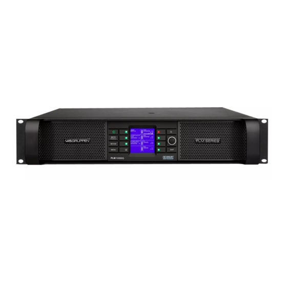
Lab.gruppen PLM Series Operation Manual (106 pages)
PLM Series Powered Loudspeaker Management systems
Brand:
Lab.gruppen
| Category:
Recording Equipment
| Size: 6 MB
Table of Contents
Table of Contents
2
2 Approvals
7
3 Warnings
7
Explanation of Graphical Symbols
7
Warning
7
Caution
7
Important Safety Instructions
8
User Responsibility
8
Mains Connection Grounding
8
Speaker Output Hazard
8
Radio Interference
9
Speaker Damage
9
4 Welcome
10
Introduction
10
Main Features
10
Amplifier Platform
10
Amplifier DSP: Gain, ISVPL ™ , Load Verification and Performance Monitoring
10
Lake ® Processing and Controller
11
Lake Analyzer Bridge
11
Dante ™ Audio Network
11
Additional Documentation
11
5 Installation
13
Unpacking
13
Mounting
13
Rear Mounting
13
Cooling
15
Operating Voltage
15
Grounding
16
6 Quick Guide Overview
17
Front Panel Overview
17
Rear Panel Overview
19
Input Connectors and Links
20
Output Connectors
21
Network Connectors
22
AC Input
23
Integrated Lake Processing
23
Lake Controller Software
23
7 Operation and Performance
25
Introduction to Operation
25
Operation Precautions
25
Power Output Performance
25
Symmetrical Power
25
Asymmetrical Power
25
Power over Time
26
Amplifier and Load Protection Systems
27
Inter-Sample Voltage Peak Limiter (ISVPL)
27
Current Peak Limiter (CPL)
28
Power Average Limiter (PAL)
28
Current Average Limiter (CAL ™ )
29
Voltage Clip Limiter (VCL)
29
Temperature Protection
29
DC Protection
29
VHF Protection
30
Short Circuit Protection
31
Power Supply
31
8 Signal Flow and Processing
32
Signal Flow
32
Level Adjustments
32
Mute Points
33
Power Output Section: Limiting and Sensitivity
33
Loudspeaker Processor Configuration
34
Modules and Frames
35
Loadlibrary ™ and Fingerprints
36
Super Modules
36
Presets
37
Module Files
37
Frame Presets
37
Subsystem Presets
37
System Presets
37
9 Front Panel Interface
38
Front Panel Navigation
38
General Description of Navigation in the PLM
38
Pinging Modules in the Lake Controller Software from the PLM
39
Key Lock Front Panel
39
Power Button
40
Mute Enable Button
40
Meter Button
40
Menu Button
40
Network Activity LED
41
Rotary Encoder
41
Exit Button
42
Soft-Function Buttons
42
Mute Functions
43
Module Input Mute
44
Module Output Mute
44
PLM Input Mute
44
Power Output Mute
45
LED Faults, Warnings, and Clip Indications
45
Green Indications
47
Red Indications
47
Yellow Indications
47
Warning and Fault Indications
48
Meter Mode
49
Meter View 2 - Module View
52
Meter View 3 - Temperature View
53
Meter View 4 - Input View
54
Meter Mode
55
Menu View
55
Module Submenu
56
Gain
56
Amp Gain
57
Limiters
57
Phase Reverse
57
Inter-Sample Voltage Peak Limiter Profile (ISVPL Profile)
58
Inter-Sample Voltage Peak Limiter Threshold (ISVPL Threshold)
58
Maxpeak Level (Maxpeaklvl)
58
Maxrms Attack (Maxrmsatk)
58
Maxrms Corner (Maxrmscor)
58
Maxrms Level (Maxrmslvl)
58
Maxrms Release (Maxrmsrel)
59
Mutes
59
Input Routing and Settings Submenu
59
Input Selection and Sensitivity Settings
60
AES/EBU Input Termination
62
Iso-Float
62
Attenuation Submenu
62
Frame Submenu
63
Frame Label
63
Firmware Version ('FW Version')
64
Frame Info
64
Latency ('Inh. Latency')
64
Factory Reset
65
Frame Reset
65
Max Output Current ('Maxoutcurr')
65
Max Output Voltage ('Maxoutvolt')
65
Network
65
Serial Number ('Serial No.')
65
Soft Reset
65
Display Adjustments
66
Display Contrast
66
Frame ID
66
IP Address
66
IP Mask
66
Latency Match
66
MAC Address
66
Network Status ('Online')
66
Channel Order
67
Dimming
67
Frame Preset Submenu
67
Loadsmart
67
Configure # of Cabinets in Parallel
67
Loadsmart Verification
68
Estimated # of Cabinets
68
Dante
69
Using the PLM as a "Break-In Box
69
10 Back Panel Interface
70
Power Inlet
70
Powercon ® Wiring Details
70
Audio Input and Links
70
Analog Inputs and Links
70
Iso-Float Electronic Balancing
71
Unbalanced Operation
71
Digital Inputs and Links
72
Speaker Output Connections
73
Speakon ® Output Connectors
73
Binding Post Output Connectors
75
RJ45 Connectors
75
11 Appendix
77
Faults and Warnings Overview
77
Maintenance
79
Factory Default Settings
79
Current Draw and Thermal Dissipation Specifications
80
Glossary of Terms, Acronyms and Abbreviations
82
12 Application Guide
85
I/O Panels
85
Power Distribution
85
Gain Structure
86
Gain / Level Optimization
87
Speaker Configurations
91
Digital Audio Interconnections
91
AES/EBU Interface
91
System Latency and Delay Compensation
92
Connections and Cabling
92
Input and Link Connectors
92
Interconnection Options
92
Cable Types and Distance Limitations
93
Signal Degradation and Loss
93
External Signal Distribution Hardware
93
Distribution Amplifiers
93
Passive Splitters
94
Additional Reference
94
Digital Clock Configuration
95
Firmware Upgrades
96
Firmware Upgrades Using the Update Utility
97
Firmware Upgrades Using the Lake Controller Software
100
Hot Swapping PLM Devices
101
Advertisement
Lab.gruppen PLM Series Operation Manual (75 pages)
PLM Series Powered Loudspeaker Management systems
Brand:
Lab.gruppen
| Category:
Recording Equipment
| Size: 5 MB
Table of Contents
Contents
2
Table of Contents
2
Approvals
6
Warnings
6
Explanation of Graphical Symbols
6
Warning
6
Caution
6
Important Safety Instructions
6
User Responsibility
7
Mains Connection Grounding
7
Speaker Output Hazard
7
Radio Interference
7
Speaker Damage
7
Maintenance
7
Welcome
8
Introduction
8
Main Features
8
Amplifier Platform
8
Amplifier DSP: Gain, ISVPL™, Load Verification and Performance Monitoring
8
Dolby Lake Processing and Controller
8
Smaartlive Integration
9
Dante Audio Network
9
Additional Documentation
9
Installation
10
Unpacking
10
Mounting
10
Rear Mounting
10
Cooling
11
Operating Voltage
12
Grounding
12
PLM Series Features
13
Front Panel Overview
13
Rear Panel Overview
15
Input Connectors and Links
15
Output Connectors
15
Network Connectors
16
AC Input
16
Integrated Dolby Lake Processing
17
Dolby Lake Controller (DLC) PLM Edition Software
17
Operation and Performance
18
Introduction to Operation
18
Operation Precautions
18
Power Output Performance
18
Symmetrical Power
18
Asymmetrical Power
18
Power over Time
18
Amplifier and Load Protection Systems
19
Inter-Sample Voltage Peak Limiter (ISVPL)
19
Current Peak Limiter (CPL)
20
Power Average Limiter (PAL)
20
Current Average Limiter (CAL)
20
Voltage Clip Limiter (VCL)
20
Temperature Protection
20
Contents
21
DC Protection
21
VHF Protection
21
Short Circuit Protection
21
Power Supply
22
Signal FLOW and Processing 8
23
Signal Flow
23
Level Adjustments
23
Mute Points
23
Power Output Section: Limiting and Sensitivity
23
Loudspeaker Processor Configuration
24
Modules and Frames
25
Loadlibrary and Fingerprints
25
Super Modules
26
Presets
26
Module Files
26
Frame Presets
26
Subsystem Presets
26
System Presets
26
Front Panel Interface 9
27
Front Panel Navigation
27
General Description of Navigation in the PLM
27
Pinging Modules in the DLC PLM Edition Software from the PLM
27
Key Lock Front Panel
28
Power Button
28
Mute Enable Button
28
Meter Button
28
Menu Button
28
Network Activity LED
29
Rotary Encoder
29
Exit Button
29
Soft Function Buttons
30
Mute Functions
30
Module Input Mute
30
PLM Input Mute
30
Module Output Mute
31
Power Output Mute
31
LED Faults, Warnings and Clip Indications
31
Green Indications
32
Red Indications
32
Yellow Indications
32
Warning and Fault Indications
33
Meter Mode
34
Meter View 1 - Home View
35
Meter View 2 - Module View
35
Meter View 3 - Temperature View
36
Menu Mode
37
Menu View
37
1 Contents
38
Module Submenu
38
Gain
38
Delay
38
Phase Reverse
38
Amp Gain
38
Limiters
38
Inter-Sample Voltage Peak Limiter (ISVPL)
39
Maxpeak Level (Maxpeaklvl)
39
Maxrms Attack (Maxrmsatk)
39
Maxrms Corner (Maxrmscor)
39
Maxrms Level (Maxrmslvl)
39
Maxrms Release (Maxrmsrel)
39
Mutes
39
Input Routing and Settings Submenu
40
Input Selection and Sensitivity Settings
40
Isofloat
41
AES/EBU Input Termination
41
Attenuation Submenu
42
Frame Submenu
42
Frame Name
42
Frame Info
42
Firmware Version ('FW Version')
43
Latency ('Inh. Latency')
43
Max Output Current ('Maxoutcurr')
43
Max Output Voltage ('Maxoutvolt')
43
Serial Number ('Serial No.')
43
Frame Reset
43
Factory Reset
43
Soft Reset
43
Network
43
Frame ID
44
IP Address
44
IP Mask
44
MAC Address
44
Network Statuses ('Online')
44
Latency Match
44
Display Adjustments
44
Dimming
44
Display Contrast
44
Frame Preset Submenu
44
Configure # of Cabinets in Parallel
45
Loadsmart Verification
45
Dante
45
Using the PLM as a "Break-In Box
46
Back Panel Interface 10
47
Power Inlet
47
Powercon Wiring Details
47
Audio Input and Links
47
Analog Inputs and Links
47
Unbalanced Operation
47
Iso-Float Electronic Balancing
48
Digital Inputs and Links
48
Speaker Output Connections
49
Speakon Output Connectors
49
Binding Post Output Connectors
50
RJ45 Connectors
50
11 Appendix
51
Faults and Warnings Overview
51
Factory Default Settings
54
Maintenance
54
Current Draw and Thermal Dissipation Specifications
55
Glossary of Terms, Acronyms and Abbreviations
56
I/O Panels
59
Power Distribution
59
Gain Structure
60
Gain / Level Optimization
61
Connecting Digital Audio Devices
65
AES/EBU Digital Audio
65
Sampling Rates and Latency
65
Interconnecting Digital Audio
66
Accessories
67
Application Hints
67
Digital Audio Cabling Recommendations
67
Distribution Amplifiers
67
Passive Splitters
67
Speaker Configurations
65
Digital Clock Configuration
68
Appendix 11
51
Application Guide 12
69
Firmware Upgrades
69
Firmware Upgrades Using the Update Utility
69
Firmware Upgrades Using the Dolby Lake Controller PLM Edition
71
Hot Swapping PLM Devices
72
Lab.gruppen PLM Series Operation Manual (75 pages)
PLM Series Powered Loudspeaker Management systems
Brand:
Lab.gruppen
| Category:
Recording Equipment
| Size: 5 MB
Table of Contents
Contents
2
Table of Contents
2
Approvals
6
Warnings
6
Explanation of Graphical Symbols
6
Warning
6
Caution
6
Important Safety Instructions
6
User Responsibility
7
Mains Connection Grounding
7
Speaker Output Hazard
7
Radio Interference
7
Speaker Damage
7
Maintenance
7
Welcome
8
Introduction
8
Main Features
8
Amplifier Platform
8
Amplifier DSP: Gain, ISVPL™, Load Verification and Performance Monitoring
8
Dolby Lake Processing and Controller
9
Smaartlive Integration
9
Dante Audio Network
9
Installation
10
Unpacking
10
Mounting
10
Rear Mounting
10
Cooling
11
Operating Voltage
12
Grounding
12
PLM Series Features
13
Front Panel Overview
13
Rear Panel Overview
15
Input Connectors and Links
15
Output Connectors
15
Network Connectors
16
10/100Base-T Network
16
Integrated Dolby Lake Processing
17
Dolby Lake Controller (DLC) PLM Edition Software
17
Operation and Performance
18
Introduction to Operation
18
Operation Precautions
18
Power Output Performance
18
Symmetrical Power
18
Asymmetrical Power
18
Power over Time
18
Amplifier and Load Protection Systems
19
Inter-Sample Voltage Peak Limiter (ISVPL)
19
Current Peak Limiter (CPL)
20
Power Average Limiter (PAL)
20
Current Average Limiter (CAL)
20
Voltage Clip Limiter
20
Temperature Protection
20
Contents
21
DC Protection
21
VHF Protection
21
Short Circuit Protection
22
Power Supply
22
Signal FLOW and Processing 8
23
Signal Flow
23
Loudspeaker Processor Configuration
24
Modules and Frames
25
Loadlibrary and Fingerprints
25
Super Modules
26
Presets
26
Module Presets
26
Frame Presets
26
Subsystem Presets
26
System Presets
26
Front Panel Interface 9
27
Front Panel Navigation
27
General Description of Navigation in the PLM
27
Pinging Modules in the DLC PLM Edition Software from the PLM
27
Key Lock Front Panel
28
Power Button
28
Mute Enable Button
28
Meter Button
28
Menu Button
28
Network Activity LED
29
Rotary Encoder
29
Exit Button
30
Soft-Function Buttons
30
Mute Functions
30
Module Input Mute
30
PLM Input Mute
30
Module Output Mute
31
Power Output Mute
31
LED Faults, Warnings and Clip Indications
32
Green Indications
33
Red Indications
33
Yellow Indications
33
Meter Mode
35
Meter View 1 - Home View
36
Meter View 2 - Module View
36
Meter View 3 - Temperature View
37
Menu Mode
38
Menu View
38
Module Submenu
39
Amp Gain
39
Delay
39
Limiters
39
Phase Reverse
39
User Gain
39
Inter-Sample Voltage Peak Limiter (ISVPL)
40
Maxpeak Level (Maxpeaklvl)
40
Maxrms Attack (Maxrmsatk)
40
Maxrms Corner (Maxrmscor)
40
Maxrms Level (Maxrmslvl)
40
Maxrms Release (Maxrmsrel)
40
Mutes
40
Input Routing and Settings Submenu
41
Input Selection and Sensitivity Settings
41
AES/EBU Input Termination
42
Isofloat
42
Attenuation Submenu
43
Frame Submenu
43
Frame Info
43
Frame Name
43
Factory Reset
44
Firmware Version ('FW Version')
44
Frame Reset
44
Latency ('Inh. Latency')
44
Max Output Current ('Maxoutcurr')
44
Max Output Voltage ('Maxoutvolt')
44
Network
44
Serial Number ('Serial No.')
44
Soft Reset
44
Dimming
45
Display Adjustments
45
Display Contrast
45
Frame ID
45
IP Address
45
IP Mask
45
Latency Match
45
MAC Address
45
Network Statuses ('Online')
45
Frame Preset Submenu
45
Loadsmart
46
Configure of Cabinets in Parallel
46
Loadsmart Verification
46
Dante
47
Break in Physical Line
47
Probe Routing
47
Back PANEL INTERFACE
48
Power Inlet
48
Powercon Wiring Details
48
Audio Input and Links
48
Analog Inputs and Links
48
Unbalanced Operation
48
Iso-Float Electronic Balancing
49
Digital Inputs and Links
49
Speaker Output Connections
50
Speakon Output Connectors
50
Binding Post Output Connectors
51
RJ45 Connectors
51
Appendix
52
Faults and Warnings Overview
52
Maintenance
55
Additional Documentation
55
Current Draw and Thermal Dissipation Specifications
55
Factory Default Settings
55
Glossary of Terms, Acronyms, Abbreviations, Etc. Used in this Manual
55
Application Guide
62
I/O Panels
62
Power Distribution
62
Gain Structure
63
Gain / Level Optimization
63
Speaker Configurations
67
Connecting Digital Audio Devices
67
AES/EBU Digital Audio
67
Sampling Rates and Latency
67
Interconnecting Digital Audio
68
Cable
68
Accessories
69
Distribution Amplifiers
69
Passive Splitters
69
Application Hints
69
Firmware Upgrades
70
Firmware Upgrades Using the Update Utility
70
Firmware Upgrades Using the Dolby Lake Controller PLM Edition
71
Hot Swapping PLM Devices
72
Advertisement
Lab.gruppen PLM Series Operation Manual (101 pages)
PLM Series Powered Loudspeaker Management systems
Brand:
Lab.gruppen
| Category:
Recording Equipment
| Size: 3 MB
Table of Contents
1 Important Safety Instructions
2
Standards
2
Explanation of Graphical Symbols
2
Warning
3
Caution
3
FCC Compliance Notice (Radio Interference)
3
User Responsibility
4
Mains Connection Grounding
4
Speaker Damage
4
Table of Contents
5
2 Welcome
7
Introduction
7
Main Features
7
Amplifier Platform
7
Lake Analyzer Bridge
8
Additional Documentation
9
3 Installation
10
Unpacking
10
Mounting
10
Rear Mounting
10
Cooling
12
Operating Voltage
12
Grounding
13
4 Product Overview
15
Front Panel Overview
15
Meter Button
16
Exit Button
17
Back Panel Overview
18
Input and Link Connectors
19
Output Connectors
19
5 Operation and Performance
22
Operation Precautions
22
Power Output Performance
22
Symmetrical Power
22
Asymmetrical Power
23
Power over Time
23
Amplifier and Load Protection Systems
24
Temperature Protection
28
Vhf Protection
29
Short Circuit Protection
30
Power Supply
30
6 Signal Flow and Lake Processing
32
Signal Flow
32
Lake Processing and Control
34
Modules and Frames
34
Super Modules
35
Loudspeaker Crossover Configuration Overview
35
Files and Presets
36
7 Front Panel Interface
37
Overview
37
Operating Modes
37
Front Panel Key Lock
38
Power Button
38
Mute Enable Button
39
Meter Button
39
Menu Button
39
Exit Button
39
Dynamic Buttons, Controls and Leds
40
Rotary Encoder
41
Mute Functions
42
Plm Input Mute
42
Module Input Mute
43
Module Output Mute
43
Power Output Mute
43
Warning and Fault Indications
45
Meter Mode
47
Menu Mode
51
Module Submenu
53
Attenuation Submenu
59
Frame Submenu
60
Loadsmart Verification
64
8 Back Panel Interface
67
Speaker Outputs
67
Analog Inputs and Outputs
71
Unbalanced Operation
72
AES3 Digital I/O
73
RJ45 Ethercon ® Network Connections
74
Power Inlet
75
9 Appendix
76
Faults and Warnings Overview
76
Maintenance
79
Factory Default Settings
79
Current Draw and Thermal Dissipation Specifications
80
Glossary of Terms, Acronyms and Abbreviations
83
10 Application Guide
86
Rack I/O Panels
86
Power Distribution
86
Gain Structure
87
Gain / Level Optimization
89
Speaker Configurations
92
Digital Audio Connections
92
System Latency and Delay Compensation
93
Connections and Cabling
93
Interconnection Options
94
External Signal Distribution Hardware
95
Distribution Amplifiers
95
Digital Clock Configuration
96
11 Technical Specifications
98
12 Warranty and Support
99
General
99
International Warranties
99
Technical Assistance and Service
99
Trademarks
100
Lab.gruppen PLM Series Operation Manual (107 pages)
PLM Series Powered Loudspeaker Management systems
Brand:
Lab.gruppen
| Category:
Recording Equipment
| Size: 15 MB
Table of Contents
1 Important Safety Instructions
2
Standards
2
Explanation of Graphical Symbols
2
Warning
3
Caution
3
FCC Compliance Notice (Radio Interference)
3
User Responsibility
4
Mains Connection Grounding
4
Speaker Damage
4
Table of Contents
5
2 Welcome
7
Introduction
7
Main Features
7
Additional Documentation
9
3 Installation
10
Unpacking
10
Mounting
10
Cooling
12
Operating Voltage
12
Grounding
13
4 Product Overview
14
Front Panel Overview
14
Back Panel Overview
17
Input and Link Connectors
18
Output Connectors
18
5 Operation and Performance
21
Operation Precautions
21
Power Output Performance
21
Asymmetrical Power
22
Power over Time
22
Amplifier and Load Protection Systems
23
Temperature Protection
27
Vhf Protection
28
Power Supply
30
6 Signal Flow and Lake® Processing
31
Signal Flow
31
Level Adjustments & Mute Points
31
Lake Processing and Control
33
Modules and Frames
34
Loudspeaker Processor Overview
35
Files and Presets
35
7 Front Panel Interface
37
Overview
37
Front Panel Key Lock
38
Power Button
39
Mute Enable Button
39
Meter Button
39
Menu Button
39
Exit Button
40
Dynamic Buttons, Controls and Leds
40
Rotary Encoder
41
Mute Functions
42
Plm Input Mute
42
Module Input Mute
43
Module Output Mute
43
Power Output Mute
43
Warning and Fault Indications
45
Meter Mode
48
Menu Mode
52
Module Submenu
54
Attenuation Submenu
61
Frame Submenu
62
Loadsmart Verification
66
8 Back Panel Interface
69
Speaker Outputs
69
Analog Inputs and Outputs
74
Unbalanced Operation
75
AES3 Digital I/O
76
RJ45 Ethercon Network Connections
77
Power Inlet
78
9 Appendix
80
Faults and Warnings Overview
80
Maintenance
84
Factory Default Settings
84
Current Draw and Thermal Dissipation Specifications
85
Glossary of Terms, Acronyms and Abbreviations
89
10 Application Guide
92
Rack I/O Panels
92
Power Distribution
92
Gain Structure
93
Gain / Level Optimization
95
Speaker Configurations
98
Digital Audio Connections
99
Connections and Cabling
100
Interconnection Options
100
External Signal Distribution Hardware
101
Distribution Amplifiers
101
Digital Clock Configuration
102
11 Technical Specifications
104
12 Warranty and Support
105
General
105
International Warranties
105
Technical Assistance and Service
105
Trademarks
106
Lab.gruppen PLM Series Quick Start Manual (38 pages)
Brand:
Lab.gruppen
| Category:
Recording Equipment
| Size: 7 MB
Table of Contents
1 Important Safety Instructions
2
Standards
2
Explanation of Graphical Symbols
2
Warning
3
Caution
3
FCC Compliance Notice (Radio Interference)
3
User Responsibility
4
Table of Contents
5
2 Welcome
7
Introduction
7
Main Features
7
Additional Documentation
9
3 Installation
10
Unpacking
10
Mounting
10
Cooling
12
Operating Voltage
12
Grounding
13
4 Product Overview
14
Front Panel Overview
14
Back Panel Overview
17
Output Connectors
18
5 Signal Flow and Lake Processing
21
Signal Flow
21
Lake Processing and Control
23
Modules and Frames
24
Loudspeaker Processor Overview
25
Files and Presets
25
6 Quick Start Tutorial
27
Introduction
27
Lake Processing and Control
27
Installing the Lake Controller Software
27
Software Installation
28
PLM Series Configuration Tutorial
29
Ethernet Configuration
29
Gain Structure
33
Gain / Level Optimization
34
7 Technical Specifications
35
8 Warranty and Support
36
Factory Service
37
Lab.gruppen PLM Series Quick Start Manual (32 pages)
PLM Series Powered Loudspeaker Management systems
Brand:
Lab.gruppen
| Category:
Recording Equipment
| Size: 2 MB
Table of Contents
Table of Contents
2
2 Approvals
4
3 Warnings
4
Explanation of Graphical Symbols
4
Warning
4
Caution
4
Important Safety Instructions
5
User Responsibility
5
Mains Connection Grounding
5
Speaker Output Hazard
5
Radio Interference
6
Speaker Damage
6
4 Welcome
7
Introduction
7
Additional Documentation
7
Lab.gruppen Documents
8
5 Installation
9
Unpacking
9
Mounting
9
Rear Mounting
9
Cooling
11
Operating Voltage
11
Grounding
12
6 Quick Start Tutorial
13
Introduction
13
Integrated Lake Processing
13
Installing the Lake Controller Software
13
Overview
13
Software and Firmware Updates
14
Networked Applications
15
How to Configure the PLM
15
Gain Settings
19
Gain / Level Optimization
20
7 Quick Guide Overview
22
Front Panel Overview
22
Rear Panel Overview
24
Input Connectors and Links
25
Output Connectors
26
Network Connectors
27
AC Input
27
Technical Specifications
28
Warranty
30
Lab.gruppen PLM Series Network Configuration Manual (17 pages)
Powered Loudspeaker Management systems
Brand:
Lab.gruppen
| Category:
Speakers
| Size: 1 MB
Table of Contents
1 Contents
2
Table of Contents
2
2 Introduction 2
3
Overview
3
Ethernet Fundamentals
3
PC Configuration
3
3 PLM Series and Dante Networking Features 3
5
Networking Overview
5
Dante Audio Network
5
Rear Panel Connections
5
4 Avoiding Single POINT of Failure (SPF) ISSUES
6
SPF Overview
6
Automatic Priority Input Switching
6
Signal Type Redundancy
7
Signal Redundancy
7
Network Port Redundancy
7
5 Network CONNECTIONS and Topologies
8
PLM Series Network Cabling
8
PLM Series Topology Overview
8
Daisy-Chained Devices
8
Star or Hub-And-Spoke Networks
9
Daisy-Chained Switches
9
Daisy-Chained Switch Ring
9
Dual Daisy-Chained Switches
9
Other Combination Networks
10
Ethernet Cabling Limitations
10
PLM / Dante Network Size Limitations
11
Wireless Network Topologies
12
Improving Wireless Accessibility
12
Using Dante in Conjunction with Wireless Networks and Low Bandwidth Devices
12
6 Network Hardware Recommendations 6
13
General Recommendations
13
Network Switches / Routers: Linksys ® SRW224G4
13
Recommended Wireless Access Points: Linksys WAP200
13
Recommended Network Cabling: Belden 1305A
14
Recommended Network Connectors: LEMO ® -Type Multipin Connector
14
7 References and Definitions 7
15
8 Additional Information
16
Lab.gruppen PLM Series Network Configuration Manual (17 pages)
PLM Series Powered Loudspeaker Management systems
Brand:
Lab.gruppen
| Category:
Recording Equipment
| Size: 1 MB
Table of Contents
1 Contents
2
Table of Contents
2
2 Introduction 2
3
Overview
3
Ethernet Fundamentals
3
PC Configuration
3
3 PLM Series and Dante Networking Features 3
5
Networking Overview
5
Dante Audio Network
5
Rear Panel Connections
5
4 Avoiding Single POINT of Failure (SPF) ISSUES
6
SPF Overview
6
Automatic Priority Input Switching
6
Signal Type Redundancy
7
Signal Redundancy
7
Network Port Redundancy
7
5 Network CONNECTIONS and Topologies
8
PLM Series Network Cabling
8
PLM Series Topology Overview
8
Daisy-Chained Devices
8
Star or Hub-And-Spoke Networks
9
Daisy-Chained Switches
9
Daisy-Chained Switch Ring
9
Dual Daisy-Chained Switches
9
Other Combination Networks
10
Ethernet Cabling Limitations
10
PLM / Dante Network Size Limitations
11
Wireless Network Topologies
12
Improving Wireless Accessibility
12
Using Dante in Conjunction with Wireless Networks and Low Bandwidth Devices
12
6 Network Hardware Recommendations 6
13
General Recommendations
13
Network Switches / Routers: Linksys ® SRW224G4
13
Recommended Wireless Access Points: Linksys WAP200
13
Recommended Network Cabling: Belden 1305A
14
Recommended Network Connectors: LEMO ® -Type Multipin Connector
14
7 References and Definitions 7
15
8 Additional Information
16
Advertisement
Related Products
LAB Gruppen PLM+ Series
Lab.gruppen PLM Series PLM 10000Q
Lab.gruppen PLM 10000Q
Lab.gruppen PLM 12K44
Lab.gruppen PLM 20K44
Lab.gruppen PLM 5K44
Lab.gruppen PLM 14000
Lab.gruppen PLM 20000Q
Lab.gruppen PLM 8K44
Lab.gruppen PLM 8K44 SP
Lab.gruppen Categories
Amplifier
Recording Equipment
Speaker System
Controller
Speakers
More Lab.gruppen Manuals
Login
Sign In
OR
Sign in with Facebook
Sign in with Google
Upload manual
Upload from disk
Upload from URL