Lab.gruppen PLM series Quick Start Manual
Hide thumbs
Also See for PLM series:
- Operation manual (107 pages) ,
- Quick start manual (32 pages) ,
- Network configuration manual (17 pages)
Table of Contents
Advertisement
Quick Links
Download this manual
See also:
Operating Manual
Advertisement
Table of Contents

Related Manuals for Lab.gruppen PLM series


Summary of Contents for Lab.gruppen PLM series
- Page 1 Quick Start and Field Reference Guide Quick Start & Field Reference Guide Operation Manual Series ™ Powered Loudspeaker Management systems ™ Rev 1.3.5 Item: QSG-PLM...
-
Page 2: Important Safety Instructions
21. An experienced user shall always supervise this professional audio equipment, especially if inexperienced adults or minors are using the equipment. 22. The US National Differences clause 16.3 requires that network cables must be flame rated VW-1. PLM Series Quick Start and Field Reference Guide Rev 1.3.5... -
Page 3: Warning
▸ Reorient or relocate the antenna. ▸ Increase the separation between the equipment and receiver. PLM Series Quick Start and Field Reference Guide Rev 1.3.5... -
Page 4: User Responsibility
There is also a risk that the unit will malfunction since it is dependent on constant airflow from front to rear. If the dust filters are not clean and the unit malfunctions, any resulting problems will not be covered by the warranty. PLM Series Quick Start and Field Reference Guide Rev 1.3.5... -
Page 5: Table Of Contents
Lake Processing and Control ......................21 Installing the Lake Controller Software ..................... 21 PLM Series Configuration Tutorial ......................23 Gain Structure ............................27 Gain / Level Optimization ........................28 Technical Specifications ........................29 Warranty and Support ..........................30 PLM Series Quick Start and Field Reference Guide Rev 1.3.5... - Page 6 General ..............................30 International Warranties ........................30 Technical Assistance and Service ......................30 Trademarks ............................31 PLM Series Quick Start and Field Reference Guide Rev 1.3.5...
-
Page 7: Welcome
For fast installation and use of this product, your welcome package includes a printed copy of the PLM Series Quick Start & Field Reference Guide which contains the information required to safely install the product and place it in service. Control and editing features are accessible via the front panel interface or via the included Lake Controller software. - Page 8 Various features of PLM Series devices are controlled by the on-board DSP, some of which are summarized in this section. 2.2.2.1 Input Gain (Sensitivity) Input gain (sensitivity) is set in the digital domain for PLM Series devices, and may be controlled via the Lake Controller software or front-panel interface. 2.2.2.2 ISVPL ™...
-
Page 9: Additional Documentation
Audio Network ™ PLM Series devices include Dante digital audio networking as standard. Utilizing the latest advances in Ethernet technology, Dante offers simplified system configuration and extremely low latency while deliver- ing very high quality uncompressed digital audio across the Lake network. The Zen automatic configuration ™... -
Page 10: Installation
Carefully open the shipping carton and check for any damage to the device or the supplied accessories. Every Lab.gruppen product is tested and inspected before leaving the factory and should arrive in perfect condition. If any damage is discovered, please notify the shipping company immediately. Only the consignee may initiate a claim with the carrier or their insurers for damage incurred during shipping. - Page 11 Installation Figure 3-1: Rear Support Bracket and Mounting Hardware Figure 3-2: Use the Washer for Fixed Installations Figure 3-3: Use Tube for Slide-On Installation PLM Series Quick Start and Field Reference Guide Rev 1.3.5...
-
Page 12: Cooling
If installing one or more PLM Series devices in a rack with other fan-cooled equipment, be sure that all the other equipment also uses front-to-rear airflow for cooling. If this precaution is not observed, there is a risk of overheating, as units with the reverse airflow will be drawing in air which has already been heated by the PLMs. -
Page 13: Grounding
Use correctly-shielded balanced audio input connections to minimise hum and interference. Please refer to section 7.1.5 of the PLM Series Operation Manual for further information. NEVER disconnect the earth (ground) pin on the mains cable (AC power cord). -
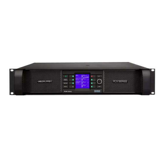
Page 14: Product Overview
Product Overview 4. Product Overview This chapter provides an overview of key features and functionality. For further information please see chapters 5 to 9 of the PLM Series Operation Manual. Front Panel Overview Figure 4-1: Front Panel Overview The front panel controls are clustered around a daylight readable LCD , allowing adjustment and monitor- ing of the majority parameters and meters. - Page 15 Please refer to chapter 6 of the PLM Series Operation Manual for further details. Standby PLM Series devices are powered on and to standby using the top-left button, or via the Lake Controller. Mute Enable Select MUTE ENABLE to allow the dynamic function buttons to operate as mute controls for the Module inputs and power output channels.
- Page 16 Module input mute functionality, mute indication and faults and warning indications relating to the PLM inputs. The bottom button is used only in Menu Mode or to lock the front panel buttons. Please refer to chapter 6 of the PLM Series Operation Manual for further details. Dynamic Function Buttons with LEDs (Right of LCD) The function of these buttons change according to the currently selected view or menu.
-
Page 17: Back Panel Overview
Product Overview Back Panel Overview Figure 4-2: Back Panel Layout Options for a 4-channel PLM Figure 4-3: Back Panel Layout Options for a 2-channel PLM PLM Series Quick Start and Field Reference Guide Rev 1.3.5... -
Page 18: Output Connectors
+26 dBu. Analog Links Two latching XLR3M connectors are fitted adjacent to the analog input connectors. These are paralleled to the input connectors to provide an unprocessed analog loop-through to feed additional PLM Series units, or other equipment. AES3 Inputs A latching XLR3F connector is provided which accepts an AES3 digital audio signal. - Page 19 Lake Processor. The daisy chain topology should not be used with Dante. For a technical reference of the Ethernet Port, please refer to section 7.3 of the PLM Series Operation Manual. Additional information is also available in the Lake Network Configuration Guide.
- Page 20 See the Lake Controller Operation Manual for further details. For a technical reference of the Ethernet Port, please refer to section 7.3 of the PLM Series Operation Manual. Additional information is also available in the Lake Network Configuration Guide.
-
Page 21: Signal Flow And Lake Processing
Signal Flow The figures below depict the audio signal flow for a PLM Series device. It is worth noting that this sophis- ticated device provides seven points in the signal chain where the signal level can be adjusted, muted or disconnected. - Page 22 The ISVPL setting is made via MENU > MODULE > LIMITERS > ISVPL, and can also be set from the Lake Controller software. Figure 5-2: Signal Flow Diagram (4-channel PLM Part 2) PLM Series Quick Start and Field Reference Guide Rev 1.3.5...
-
Page 23: Lake Processing And Control
PSU temperature to the appropriate protection circuits. Please refer to section 5.3 on page 17 further details. Table 5-1 lists PLM Series analog input sensitivity in dBu and Vrms for various Amp Gain settings and maximum/minimum ISVPL settings, assuming an analog input headroom of 26 dBu. -
Page 24: Modules And Frames
In addition to the standard loudspeaker presets (Module files), the Lake Controller also includes a set of enhanced Module files specifically for use with the PLM Series. These supplementary PLM Module files, known as the LoadLibrary incorporate both Lake DSP parameters along with PLM specific data;... -
Page 25: Loudspeaker Processor Overview
Signal Flow and Lake Processing Loudspeaker Processor Overview The Lake Processing system within PLM Series devices may be configured with up to two processing Modules containing a total of up to six processing Module outputs, although the number of power outputs will be either two or four depending on the PLM model being used. - Page 26 Using the System Presets function in the Lake Controller, entire system configurations can be stored and recalled across a network of LM & PLM Series devices. This enables fast retrieval and switching of entire system configurations as minimal data is being sent between the Controller and Processors.
-
Page 27: Quick Start Tutorial
Lake Processing and Control PLM Series products contain an integrated Lake loudspeaker management system, providing crossovers, EQ, dynamics and other functions. Primary control is via the supplied Lake Controller software, although many functions can be accessed via the front panel interface. -
Page 28: Software Installation
6.3.4 Software and Firmware Updates Regular software and firmware updates are available for the Lake Controller software and PLM Series devices. Please check for updates regularly to ensure you have the latest features and improvements, and review the release notes to ensure familiarity with new features and other improvements. -
Page 29: Plm Series Configuration Tutorial
This tutorial provides a step-by-step guide for configuration of a typical professional loudspeaker system and provides an overview of the basic features and operation of PLM Series devices. This tutorial uses the Lake Controller software for configuration, although many steps are also available via the front panel interface. - Page 30 Locate the small square block labeled POST EQ towards the bottom of Module A’s block diagram. A setting of POST EQ indicates that the Auxiliary output channel is fed from same audio source and the 3-way crossover. PLM Series Quick Start and Field Reference Guide Rev 1.3.5...
- Page 31 The following settings on the left-side of the I/O CONFIG screen should be correct by default; if they are incorrect, please refer to the Lake Controller Operation Manual for further details. ▸ DIGITAL CLOCK: Internal – 96 kHz PLM Series Quick Start and Field Reference Guide Rev 1.3.5...
- Page 32 Unmute the Module Input by tapping the red MUTED button; the button turns blue and reads UNMUTED. Start playback of audio through the mixing console and turn up the volume of the MAIN and SUB- WOOFER channels from the mixing console. PLM Series Quick Start and Field Reference Guide Rev 1.3.5...
-
Page 33: Gain Structure
Lake Controller Operation Manual for detailed information on these features. Gain Structure The PLM Series architecture provides gain adjustments at various points in the signal path and therefore, various places for muting and level adjustment. Each mute or gain adjustment point serves a different purpose. -
Page 34: Gain / Level Optimization
If full or high average power is not required, the Module input gain may be reduced. PLM Series Quick Start and Field Reference Guide Rev 1.3.5... -
Page 35: Technical Specifications
Note 2): Separate 230 V or 115 V versions available. Not selectable on the product. All specifications are subject to change without notice. PLM Series Quick Start and Field Reference Guide Rev 1.3.5... -
Page 36: Warranty And Support
8. Warranty and Support General This product is manufactured by Lab.gruppen, and it is warranted to be free from any defects caused by components or factory workmanship, under normal use and service, for a period of six (6) years from date of purchase from an authorized Lab.gruppen dealer. -
Page 37: Factory Service
Warranty and Support 8.3.2 Factory Service In the event a Lab.gruppen product requires factory service, you may contact Lab.gruppen’s service depart- ment for return instructions and a Return Authorization number. Please note for product return: Use the original packing. Include a copy of the sales receipt, your name, return address, phone and fax number, email address and description of the defect. - Page 38 Quick Start and Field Reference Guide Operation Manual L A B . G R U P P E N A B ► S W E D E N I N T E R N A T I O N A L C O N T A C T ► I N F O @ L A B G R U P P E N . C O M U S &...
Need help?
Do you have a question about the PLM series and is the answer not in the manual?
Questions and answers