Sign In
Upload
Manuals
Brands
JLG Manuals
Boom Lifts
Lull 1044C-54 II Series
JLG Lull 1044C-54 II Series Manuals
Manuals and User Guides for JLG Lull 1044C-54 II Series. We have
1
JLG Lull 1044C-54 II Series manual available for free PDF download: Service Manual
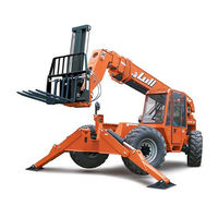
JLG Lull 1044C-54 II Series Service Manual (382 pages)
Brand:
JLG
| Category:
Boom Lifts
| Size: 26 MB
Table of Contents
July
3
Table of Contents
5
Section 1 - Safety
23
General
23
Caution, Warning, and Danger
23
Maintenance Safety
24
General
24
Mounting and Dismounting
24
Before Servicing the Machine
24
Fuel Hazards
25
Engine Coolant Hazards
25
Hydraulic System Hazards
26
Electrical System Hazards
26
Tire and Wheels Hazards
27
Rollover Protective Structure (ROPS) and Falling Object Protective Structure (FOPS)
28
Safety Standard
24
Decals and Placards
28
General
28
Cleaning Decals
28
Attaching Decals
29
Decal Locations
29
Fig. 1-1: Decals and Placards
30
Fig. 1-2: Instrument Panel Decals
30
Fig. 1-3: Control Decals
31
Fig. 1-4: Disconnect Battery Decal and Slow Moving Vehicle Sign
31
Fig. 1-5: Steer Selector Plate
32
Fig. 1-6: Hydraulic Reservoir/Fuel Tank Decals
32
Fig. 1-7: Fork Carriage Decals
32
Section 2 - Identification and Specifications
33
Serial Number Locations
35
Machine Serial Number
35
Fig. 2-1: Machine Serial Number Plate
35
Engine Serial Number, John Deere
36
Fig. 2-2: Engine Serial Number - John Deere
36
Attachment Serial Number Plate
37
Axle Serial Number
37
Fig. 2-3: Axle Serial Number
37
Fig. 2-4: Attachment Serial Number Plate
37
Identification
38
Fig. 2-5: Top View
38
Fig. 2-6: Left Side View
38
Specifications
39
Engine Specifications
42
John Deere 4045T
42
Section 3 - General Maintenance
43
General Instructions
45
Service Preparation Procedures
45
Service and Repair Procedures
46
Replacement Parts
47
General
47
Lubrication
47
Fluid and Lubricant Specifications
48
Engine Oil Specifications
48
General Specifications
48
Table 3-1: General Fluid and Lubricant Specifications
48
Table 3-2: John Deere Engine Oil Specifications
49
Table 3-3: ZF Transmission Oil Specifications
49
Transmission Oil Specifications
49
Fuel Requirements
50
Grease
50
Care and Cleaning
51
Cleaning Exterior Surfaces
51
Cleaning the Cab
51
Attaching Decals
52
Cleaning Decals
52
Storage
52
Preparing the Machine for Long-Term Storage
52
Preparing the Machine after Long-Term Storage
53
Torque Specifications
54
General Torques for Standard Bolts, Capscrews, and Nuts
54
Fig. 3-1: SAE Grade Identification
54
Fig. 3-4: Metric Class Identification
57
Hydraulic Fitting Torques
58
Table 3-4: Torque for JIC and SAE Female Swivel Nuts
58
Table 3-5: Torque for Non-Adjustable O-Ring Fittings
58
Table 3-6: Torque for Adjustable O-Ring Fittings
59
Table 3-7: Torque for O-Ring Plugs
59
Jump Starting Procedures
60
Table 3-8: Pipe Thread Fittings (Steel)
60
Conversion Charts
62
Table 3-9: Inch Fraction, Decimal, and Metric Conversion Chart
62
Table 3-10: Miscellaneous Conversions
63
MID-Inlet Hydraulic Schematic . . . . . . . . . . . . . . . . . . . . . . . . . . . . . . . . . . . . . . . . . . . . . . . . . . . . . . . Diagram
65
Section 4 - Reference Diagrams
67
Control Valve
74
Section 5 - Supply, Pressure, and Return Hydraulics
79
General
83
Major System Components
83
General Description
83
Fig. 5-1: Major Hydraulic Components
83
Hydraulic Systems
85
General Hydraulic Maintenance Practices
85
Safe Maintenance Practices
85
Fig. 5-2: MID-Inlet Hydraulic Components
85
Cleanliness
86
Checking Hydraulic Lines
87
Hydraulic Reservoir
88
Description
88
Fig. 5-3: Hydraulic Reservoir Location
88
Fig. 5-4: Hydraulic Reservoir
89
Filling Hydraulic Reservoir
90
Fig. 5-5: Recommended Reservoir Filling Method
90
Hydraulic Reservoir
90
Description
90
Fig. 5-6: Alternate Reservoir Filling Method
91
Reservoir Drain and Refill
93
Fig. 5-7: Hydraulic Reservoir Drain and Refill
93
Removal
95
Fig. 5-8: Hydraulic Reservoir/Fuel Tank Installation
95
Installation
97
Sight Gauge
98
Description
98
Fig. 5-9: Hydraulic Reservoir Sight Gauge
98
Removal
99
Fig. 5-10: Reservoir Sight Gauge Installation
99
Installation
100
Suction Strainer
101
Description
101
Fig. 5-11: Suction Strainer Installation
101
Installation
102
Removal and Cleaning
102
Hydraulic Return Filter
103
Checking Filter Condition
103
Description
103
Fig. 5-12: Hydraulic Return Filter
103
Fig. 5-13: Return Filter Pressure Gauge
103
Replacing Return Filter Element
104
Fig. 5-14: Filter Housing Cover
104
Fig. 5-15: Filter Element Assembly
105
Removal
107
Fig. 5-16: Return Filter Assembly
107
Installation
108
Reservoir Breather
108
Description
108
Fig. 5-17: Reservoir Breather
108
Removal and Installation
109
Hydraulic Pressure Filter
109
Description
109
Fig. 5-18: Hydraulic Pressure Filter - Control Manifold Hydraulics
109
Replacing Pressure Filter Element
110
Fig. 5-19: Hydraulic Pressure Filter Element
110
Removal
111
Fig. 5-20: Hydraulic Pressure Filter Assembly
111
Installation
112
Hydraulic Pump
112
Description
112
Fig. 5-21: Hydraulic Pump Location
112
Troubleshooting Pump Problems
113
Removal
115
Fig. 5-22: Hydraulic Pump Hoses - MID-Inlet Hydraulics
115
Hydraulic Pump
115
Fig. 5-23: Hydraulic Pump Installation - MID-Inlet Hydraulics
117
Installation
119
Checking Pump Flow Rate
120
Fig. 5-24: Checking Hydraulic Pump Flow Rate
120
MID-Inlet Control Valve
122
Description
122
Fig. 5-25: MID-Inlet Control Valve Location
122
Fig. 5-26: MID-Inlet Control Valve Components
122
Fig. 5-27: MID-Inlet Control Valve Configurations
124
Removal
125
Fig. 5-28: MID-Inlet Control Valve Installation
125
Installation
126
Rear Axle Stabilizer Control Valve
126
Description
126
Fig. 5-29: Rear Axle Stabilizer Control Valve Location
126
Fig. 5-30: Rear Axle Stabilizer Control Valve Ports
127
Table 5-1: Rear Axle Stabilizer Control Valve Markings
128
Removal, Rear Axle Stabilizer Control Valve
129
Fig. 5-31: Rear Axle Stabilizer Control Valve
129
Boom Extend Lockout Valve
131
Description
131
Fig. 5-32: Boom Extend Lockout Valve
131
Fig. 5-33: Hydraulic Diagnostic Ports - Models with MID-Inlet Hydraulics
131
Hydraulic Diagnostic Ports
131
General
131
Fig. 5-34: Roll-Back Hose Frame Location - Control Manifold Hydraulics
133
General
133
Removal
133
Fig. 5-35: Roll-Back Tray Installation - MID-Inlet Hydraulics
134
Installation
135
Roll-Back Hose Tray
133
Section 6 - Boom and Transfer
143
Boom and Transfer Hydraulics
143
Fig. 6-1: Major Boom and Transfer Hydraulic Components
143
Joystick Controls
143
Joystick Controls
144
General Description
143
Fig. 6-2: Joystick
144
Removal
145
General Description
144
Fig. 6-3: Joystick Installation
145
Installation
146
Disassembly
147
Fig. 6-4: Joystick Components
147
Fig. 6-5: Pilot Pressure Diagnostic Port
150
Hydraulic Cylinders
151
Description
151
Fig. 6-6: Pilot Pressure Plug
151
Checking Cylinder Condition
152
Boom Hoist Cylinder
154
Description
154
Fig. 6-7: Boom Hoist Cylinders
154
Removal
155
Fig. 6-8: Boom Hoist Cylinder Installation
155
Installation
156
Overhaul
157
Fig. 6-9: Boom Hoist Cylinder Assembly
157
Front Carriage Tilt Cylinder
160
Description
160
Fig. 6-10: Front Carriage Tilt Cylinder
160
Removal
161
Fig. 6-11: Front Carriage Tilt Cylinder Installation
161
Installation
162
Overhaul
163
Fig. 6-12: Front Carriage Tilt Cylinder Assembly
163
Rear Carriage Tilt Cylinder
166
Description
166
Fig. 6-13: Rear Carriage Tilt Cylinder
166
Removal
167
Fig. 6-14: Rear Carriage Tilt Cylinder Installation
167
Installation
168
Overhaul
169
Fig. 6-15: Rear Carriage Tilt Cylinder Assembly
169
Selector Valve
171
Description
171
Fig. 6-16: Selector Valve
171
Removal
172
Fig. 6-17: Selector Valve Installation
172
Installation
173
Overhaul
173
Fig. 6-18: Selector Valve Assembly
173
Troubleshooting
175
Boom Slide Pads - General
176
Description
176
Slide Pad Inspection
176
Fig. 6-19: Load Bearing Pad
176
Fig. 6-20: Pad Worn, but Still OK
177
Fig. 6-21: Pad Must be Replaced
177
Fig. 6-22: Bolted Boom Slide Pad
177
Lubrication
178
Slide Area Surface Finish
178
Fig. 6-23: Slide Pad Without Chamfers - 3 and 4-Section Boom
178
Fig. 6-24: Damaged Slide Surface
179
Fig. 6-25: Slide Surface Repair
179
Replacing and Shimming Boom Slide Pads - General
180
Fig. 6-26: Slide Pad Installation (2-Section Shown)
180
Fig. 6-27: Positioning Retaining Block
180
Fig. 6-28: Determining Capscrew Length
181
Fig. 6-29: Correctly Installed Capscrew
181
Quick Attach
182
Description
182
Disconnecting an Attachment
182
Fig. 6-30: Quick Attach Rear View
182
Fig. 6-31: Release Handle
182
Fig. 6-32: Lock Plate
183
Fig. 6-33: Rotating Quick Attach Downwards
183
Fig. 6-34: Lowering Boom
183
Connecting an Attachment
184
Fig. 6-35: Retracting Boom
184
Fig. 6-36: Extending Boom
184
Fig. 6-37: Raising Boom
184
Fig. 6-38: Rotating Quick Attach Forward
185
Fig. 6-39: Lock Plate Engaged
185
Removal
186
Fig. 6-40: Lower Pivot of Carriage Tilt Cylinder
186
Installation
187
Fig. 6-41: Quick Attach Pivot
187
Boom Angle Inclinometer
188
Description
188
Fig. 6-42: Boom Angle Inclinometer
188
Fig. 6-43: Boom Angle Inclinometer Installation
188
4-Section Boom
189
Replacement
188
Description
189
Fig. 6-44: 4-Section Boom
189
Shimming Procedures
190
Fig. 6-45: Boom Slide Pad Locations - 4-Section Boom
190
Fig. 6-46: Boom Section Gaps - Front of 4-Section Boom
190
Fig. 6-47: Lower Shim Installation - Front of 4-Section Boom
191
Fig. 6-48: Upper Shim Installation - Front of 4-Section Boom
191
Fig. 6-49: Boom Section Gaps - Rear of 4-Section Boom
192
Fig. 6-50: Lower Shim Installation - Rear of 4-Section Boom
192
Fig. 6-51: Upper Shim Installation - Rear of 4-Section Boom
193
Fig. 6-52: Clearances between Boom Sections - Rear of 4-Section Boom
193
Fig. 6-53: Gaps between Pads and Boom - Rear of 4-Section Boom
194
Fig. 6-54: Clearances between Boom Sections - Front of 4-Section Boom
194
Inspection Procedures
195
Fig. 6-55: Gaps between Pads and Boom - Front of 4-Section Boom
195
Fig. 6-56: Inner Boom Cross-Section at Window
196
Fig. 6-57: Middle (Forward) Boom Cross-Section at Window
196
Boom Removal
197
Fig. 6-58: Middle (Forward) Boom Cross-Section at Window
197
Fig. 6-59: 4-Section Boom Cover Installation
198
Fig. 6-60: Hose Connections, 4-Section Boom
198
Fig. 6-61: Cylinder Pivot Pins
199
Fig. 6-62: Upper Rear Slide Pad Removal - Middle (Rear) Boom Section
200
Fig. 6-63: Upper Rear Slide Pad Removal - Middle (Forward) Boom Section
201
Fig. 6-64: Upper Rear Slide Pad Removal - Inner Boom Section
201
Fig. 6-65: Locations for Chain Attachment - Inner Boom Section
202
Fig. 6-66: 4-Section Boom Pivot Pins
203
Installation
204
Boom Disassembly
205
Boom Extension Proximity Switch
206
Fig. 6-67: Slide Pad Removal - Outer Boom Section
206
Description
206
Fig. 6-68: Lower Front Slide Pad Removal - Middle (Rear) Boom Section
207
Fig. 6-69: Disconnecting Hoses between Sections
208
Fig. 6-70: Extension Cylinder Removal - 4-Section Boom
209
Fig. 6-71: Upper Front Slide Pad Removal - Middle (Rear) Boom Section
210
Fig. 6-72: Upper Front Slide Pad Removal - Middle (Forward) Boom Section
211
Fig. 6-73: Upper Chain - Middle (Forward) to Middle (Rear) Boom Sections
211
Fig. 6-74: Upper Chain Roller Assembly - Middle (Forward) Boom Section
212
Fig. 6-75: Disconnecting Chains at Rear of Inner Boom
213
Fig. 6-76: Disconnecting Chains at Rear of Middle (Forward) Boom
213
Fig. 6-77: Slide Pad Removal - Inner Boom Section
214
Fig. 6-78: Slide Pad Removal - Middle (Forward) Boom Section
215
Fig. 6-79: Grease Hose Assembly
216
Fig. 6-80: Rear Chain Roller Removal - Middle (Forward) Boom Section
217
Fig. 6-81: Hose and Tube Removal - Inner Boom Section
218
Fig. 6-82: Upper Chain Assembly
219
Fig. 6-83: Upper Chain Roller Assembly - Middle (Rear) Boom Section
219
Fig. 6-84: Removing Lower Chains
220
Fig. 6-85: Slide Pads - Middle (Rear) Boom Section
221
Fig. 6-86: Chain and Hose Guide Assembly
222
Fig. 6-87: Tubes and Hoses - Middle (Rear) and Outer Boom Sections
223
Fig. 6-88: Side Slide Pads - Outer Boom Section
224
Fig. 6-89: Outer Boom Tubes and Hoses
225
Assembly
226
Fig. 6-90: Outer Boom Tube and Hose Assembly
227
Fig. 6-91: Extension Cylinder Installation
228
Fig. 6-92: Lower Chains on Outer Boom Section
229
Fig. 6-93: Lower Rear Slide Pad Installation - Middle (Rear) Boom Section
230
Fig. 6-94: Tubes and Hoses - Middle (Rear) Boom Sections
231
Fig. 6-95: Chain and Hose Guide Assembly
232
Fig. 6-96: Installation of Lower Chain - Middle (Rear) Boom Section
233
Fig. 6-97: Upper Chain Roller Assembly - Middle (Rear) Boom Section
234
Fig. 6-98: Chain Roller Assemblies - Middle (Forward) Boom Section
235
Fig. 6-99: Slide Pad Installation - Middle (Forward) Boom Section
236
Fig. 6-100: Hydraulic Hose and Tube Installation - Inner Boom Section
237
Fig. 6-101: Slide Pad Installation - Inner Boom Section
238
Fig. 6-102: Grease Hose Installation
238
Fig. 6-103: Upper Chain Installation - Inner Boom Section
239
Fig. 6-104: Upper Slide Pad Installation - Front of Middle (Forward) Boom Section
240
Fig. 6-105: Upper Chain and Hose Reel Assembly - Middle (Forward) Boom
241
Fig. 6-106: Rear Slide Pad Installation
241
Fig. 6-107: Front Slide Pad Installation - Outer and Middle (Rear) Boom Sections
242
Fig. 6-108: Lower Chain Installation - Inner Boom Section
243
Fig. 6-109: Lower Chain Installation - Middle (Forward) Boom Section
243
Fig. 6-110: Upper Chains - Middle (Rear) to Outer Boom Sections
244
Fig. 6-111: Upper Chain - Middle (Forward) to Middle (Rear) Boom Sections
245
Fig. 6-112: Securing Lower Chains - Middle (Rear) and Outer Boom Sections
245
Fig. 6-113: Securing Boom Extension Cylinder
246
Fig. 6-114: Connecting Hoses between Sections
247
Boom Extend and Retract Chains
248
Chain Lubrication
249
Boom Chain Tension Check
250
Fig. 6-115: Boom Tension Check
250
Boom Hose Replacement
251
Extension Cylinder
253
Fig. 6-116: 4-Section Boom Extension Cylinder
253
Fig. 6-117: 4-Section Boom Extension Cylinder Installation
254
Fig. 6-118: 4-Section Boom Extension Cylinder Assembly
256
Boom Extension Proximity Switch
259
Description
259
Fig. 6-119: Boom Extension Proximity Switch
259
Removal
260
Fig. 6-120: Boom Extension Proximity Switch Operation
260
Fig. 6-121: Boom Extension Proximity Switch Assembly
260
Adjustments
261
Installation
261
Fig. 6-122: Boom Extension Proximity Switch Adjustment
261
Transfer Carriage
262
Description
262
Fig. 6-123: Transfer Carriage
262
Fig. 6-124: Disconnecting Transfer Cylinder from Transfer Carriage
263
Fig. 6-125: Boom Elevation Proximity Switch Wiring
264
Fig. 6-126: Boom Cover Installation
264
Fig. 6-127: Boom Extension Proximity Switch Wiring
265
Fig. 6-128: Disconnecting Hydraulic Hoses from Transfer Carriage
266
Fig. 6-129: Transfer Carriage with Boom Installation
267
Fig. 6-130: Transfer Carriage Installation
268
Installation
269
Rollers, Bushings, and Shims
271
Fig. 6-131: Transfer Carriage - Front Rollers, Bushings, and Shims
271
Fig. 6-132: Shims for Front Transfer Rollers
272
Fig. 6-133: Scraper Plate
273
Fig. 6-134: Transfer Carriage - Rear Rollers, Bushings, and Shims
274
Fig. 6-135: Spacer Washers for Rear Transfer Rollers
275
Fig. 6-136: Rear Slide Block Installation
276
Section 7 - Frame Tilt and Oscillation
279
Frame Tilt System
283
General Description
283
Circuit Description
283
Fig. 7-1: Frame Tilt System Components
283
Frame Tilt Control Valve
285
Description
285
Fig. 7-2: Frame Tilt Control Valve
285
Removal
286
Fig. 7-3: Frame Tilt Control Valve Installation
286
Installation
287
Overhaul
288
Fig. 7-4: Frame Tilt Control Valve (Exploded View)
288
Frame Tilt Cylinder
290
Description
290
Fig. 7-5: Frame Tilt Cylinder
290
Removal
291
Fig. 7-6: Frame Tilt Cylinder Installation
291
Installation
292
Overhaul
294
Fig. 7-7: Frame Tilt Cylinder (Exploded View)
294
Counterbalance Valve Cartridge
297
Fig. 7-8: Counterbalance Valve Cartridges, Frame Tilt Cylinder
297
Frame Level Indicator
298
Adjustment
298
Description
298
Fig. 7-10: Leveling the Frame
298
Rear Oscillation Lock System
299
Fig. 7-9: Frame Level Indicator
298
General Description, Models with Control Manifold Hydraulics
299
Theory of Operation and Circuit Logic
300
Fig. 7-12: Circuit Operation above 40°
301
Fig. 7-13: Circuit Operation above 20° below 40°
302
Fig. 7-14: Circuit Operation above 20° below 40° with Service Brake Applied
303
Table 7-1: Rear Oscillation Lock Circuit Test Matrix
305
Testing Rear Oscillation Lock Circuit
305
Rear Oscillation Lock Cylinder
306
Description
306
Fig. 7-16: Rear Oscillation Lock Cylinder
306
Removal
307
Fig. 7-17: Rear Oscillation Lock Cylinder Installation
307
Installation
308
Overhaul
310
Fig. 7-18: Rear Oscillation Lock Cylinder (Exploded View)
310
Oscillation Control Block
313
Description
313
Fig. 7-19: Oscillation Control Block
313
Removal
314
Fig. 7-20: Oscillation Control Block Installation
314
Installation
316
Overhaul
317
Fig. 7-21: Oscillation Control Block (Exploded View)
317
Boom Elevation Proximity Switch
319
Description
319
Fig. 7-22: Boom Elevation Proximity Switch
319
Removal
320
Fig. 7-23: Boom Elevation Proximity Switch Operation
320
Fig. 7-24: Boom Elevation Proximity Switch Assembly
320
Adjustment
321
Installation
321
Fig. 7-25: Boom Elevation Proximity Switch Adjustment
321
Section 8 - Transmission
323
Transmission Assembly Component Terminology
325
Transmission Description
325
Fig. 8-1: ZF Transmission
325
Transmission Operation
326
Fig. 8-2: Transmission Serial Number Plate Location
327
Transmission Maintenance
328
Transmission General Specification
327
Transmission Lubrication
327
Transmission Performance Specification
327
Transmission Specifications
327
Fig. 8-3: the Lubrication and Maintenance Flip Chart
328
Fig. 8-4: Transmission Oil Cooler Hose Connections
329
Transmission Removal
330
Fig. 8-5: Disconnect the Battery Negative (-) Cable
331
Fig. 8-6: Drain Transmission Oil
331
Fig. 8-7: Transmission Oil Cooler Hose Connections
332
Fig. 8-8: Remove Transmission from Frame
333
Transmission Inspection and Internal Repair
334
Transmission Installation
334
Fig. 8-9: Transmission External Components
334
Fig. 8-10: Install the Transmission
335
After Transmission Service or Replacement
336
Fig. 8-11: Transmission Oil Cooler Hose Connections
336
Transmission Shift Logic
337
Troubleshooting
339
Fig. 8-12: Transmission Shift Logic Schematic
339
Transmission Troubleshooting
340
Section 9 - Axles and Brakes
343
Axle and Drive Shaft Component Terminology
345
General Information
345
Fig. 9-1: Axle and Drive Shaft
345
Axle Assembly
346
Axle Installation
349
Axle Service and Troubleshooting
350
Drive Shafts
351
Drive Shaft Maintenance
352
Driveshaft Removal
352
Transmission-To-Axle Drive Shaft
353
Axle Inspection, Internal Service and Repair
349
Drive Shaft Disassembly
353
Drive Shaft Assembly
354
Fig. 9-2: Service Brake Pedal Pressure Switch
356
Service Brakes
356
Service Brake Pressure Switch Replacement
356
Fig. 9-3: Accumulator
357
Pre-Charging Accumulator
358
Precautions
358
General
357
Fig. 9-4: Accumulator Charging
359
Checking Pre-Charge
360
Accumulator
357
Towing a Disabled Machine
361
Fig. 9-5: Park Brake Hoses
361
Manually Releasing the Park Brake
362
Manually Resetting the Park Brake
362
Section 10 - Outriggers
365
Outriggers
365
Fig. 10-1: Outriggers
365
Removal
366
General
365
Fig. 10-2: Outrigger Installation
366
Installation
367
Outrigger Cylinders
368
Fig. 10-3: Outrigger Cylinders
368
Removal
369
General
368
Fig. 10-4: Outrigger Cylinder Installation
369
Installation
370
Overhaul
371
Fig. 10-5: Outrigger Cylinder Assembly
371
Differential Pressure Switch
373
Description
373
Boom Extension Proximity Switch
374
Description
374
Fig. 10-6: Boom Extension Proximity Switch
374
Removal
375
Fig. 10-7: Boom Extension Proximity Switch Operation
375
Fig. 10-8: Boom Extension Proximity Switch Assembly
375
Adjustments
376
Installation
376
Fig. 10-9: Boom Extension Proximity Switch Adjustment
376
Outrigger Control Valves
377
Description
377
Fig. 10-10: Outrigger Controls
377
Removal
378
Fig. 10-11: Outrigger Control Valve Installation
378
Installation
379
Advertisement
Advertisement
Related Products
JLG 10VP
JLG 100HX
JLG 100HX+10
JLG TOUCAN 1010
JLG TOUCAN 1010 I
JLG 1030P
JLG 100SX
JLG 1043
JLG 1055
JLG 110SXJ
JLG Categories
Boom Lifts
Lifting Systems
Scissor Lifts
Construction Equipment
Work Light
More JLG Manuals
Login
Sign In
OR
Sign in with Facebook
Sign in with Google
Upload manual
Upload from disk
Upload from URL