Sign In
Upload
Manuals
Brands
iDirect Manuals
Network Router
iconnex e800
iDirect iconnex e800 Manuals
Manuals and User Guides for iDirect iconnex e800. We have
2
iDirect iconnex e800 manuals available for free PDF download: Installation Manual, Installation And Safety Manual
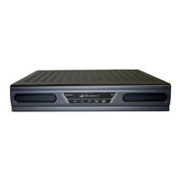
iDirect iconnex e800 Installation Manual (130 pages)
Satellite Routers
Brand:
iDirect
| Category:
Network Router
| Size: 6.4 MB
Table of Contents
Revision History
3
Table of Contents
4
List of Figures
9
About
13
Intended Audience
13
Document Conventions
14
Related Documents
14
Getting Help
15
1 Getting Started
17
When to Use this Guide
17
How to Use this Guide
17
Required Equipment
18
Required Software
18
Extracting Files
19
Software Package Components
19
PC Firewall
20
Figure 1. Allowing Isite in Windows Firewall
21
2 Site Considerations
23
Selecting a Site
23
Assembly
23
Orientation
24
Magnetic Variation
24
Figure 2. Example: Magnetic Declination
24
Sighting Antenna Azimuth
25
Elevation Offset
25
Figure 3. Antenna Elevation Offset
26
Part One: Isite
27
3 Connecting to the LAN Port
29
IP Address
29
Local Area Connection
30
Figure 4. Local Area Connection Status Dialog Box
30
Figure 5. Local Area Connection Properties Dialog Box
31
Figure 6. Internet Protocol (TCP/IP) Dialog Box
31
Table 1. LAN Ports for Ethernet Cable Connections
32
Retrieving the IP Address Using the Console Port
33
Connecting to the Console Port
33
Figure 7. Putty Session Options Dialog Box
33
Figure 8. Putty Configuration: Serial Parameters
34
Logging in to the Idirect Application
35
Figure 9. Root Login and Linux Prompt
35
Figure 10. Telnet and Login to Idirect Application
35
Retrieving the IP Address
36
Figure 11. Entering the Laninfo Command
36
4 Loading Packages with Isite
37
Logging in to Isite
37
Figure 12. Welcome Screen and New Element Creation
38
Figure 13. Logging in to New Element
38
Loading BSP and Remote Images
39
Table 2. IDX Release 3.3 Remote Software Packages by Model Type
39
Figure 14. Selecting the BSP File
40
Figure 15. Download Package Dialog Box Settings
41
Figure 16. Information Window: File Transfer Progress
41
5 Loading Options Files with Isite
43
Options File
43
Figure 17. Loading the Options File
43
Figure 18. Open Dialog Box with Remote Options File Selected
44
Figure 19. Resetting the Satellite Router after Download
44
6 Configuring TRANSEC ACC Keys
45
Prerequisites
45
Commissioning Without an X.509 Certificate
45
Loading ACC Keys
46
Figure 20. ACC Key Example
46
7 Pointing the Antenna with Isite
47
Preparation
47
Initial Alignment
47
Calculating Look Angle
47
Figure 21. Isite Antenna Pointing Dialog Box: Look Angle Calculator
48
Coarse Alignment
49
Peak Indicators
49
Pwm
50
Histogram
50
Peaking the Antenna
50
Table 3. PWM Voltage Ranges and Signal Status
50
Figure 22. Starting Antenna Pointing
51
Figure 23. Antenna Pointing Histogram and Current Signal Strength
52
Part Two: Web Isite
55
8 Connecting with Web Isite
57
Web Isite
57
IP Address
57
Restoring Factory Defaults
58
X1 Indoor/Outdoor
58
Figure 24. X1 Indoor Rear Panel: Reset Access Hole
58
Figure 25. X1 Outdoor Front Panel: Reset Button
59
E150
60
Figure 26. Evolution X7 Reset Button: Location
60
Cold Start: X1 Outdoor
61
Table 4. Evolution X1 Outdoor Warm-Up Periods
61
9 Loading Packages with Web Isite
63
Logging in to Web Isite
63
Figure 27. Connecting to the Satellite Router Using Web Isite
63
Figure 28. Web Isite Login Page
64
Figure 29. Web Isite Dashboard Example: Evolution X7
64
Loading the Package File
65
Figure 30. Web Isite File Management Page: Load Sections
65
Table 5. IDX Release 3.3 Remote Software Packages
65
Figure 31. Selecting Package File
66
Figure 32. Load Package Status Box
66
10 Loading Options Files with Web Isite
69
Options File
69
Figure 33. File Management: Load Options File
70
Figure 34. Load Options File Status Box
70
Figure 35. Evolution X7 with Latest Software in both Partitions
71
Downstream Template
72
Figure 36. Downstream Template: Example
72
Figure 37. Web Isite Downstream Configuration Page
73
Figure 38. Restart Confirmation Box
74
11 Pointing the Antenna with Web Isite
75
Preparation
75
Initial Alignment
75
Calculating Look Angle
75
Figure 39. Web Isite Commissioning Dialog Box: Angle Calculator
76
Coarse Alignment
77
Peak Indicators
77
Pwm
77
Graphic Display
78
Peaking the Antenna
78
Table 6. PWM Voltage Ranges and Signal Status
78
Figure 40. Web Isite Antenna Pointing Graphic Display: X7
79
Figure 41. Web Isite: Antenna Peak Indication
80
12 Over the Air Download
83
Software Package and Options Push
83
Options File Only Push
85
Verify the Download
85
Figure 42. Web Isite: Confirming the Software Version
86
Figure 43. Web Isite: ODU Status
86
Figure 44. View Options File: Frequency Translation
87
Part Three: Commissioning
89
13 Setting Geo Location for Secure Mobiles
91
Secure Mobile Remotes
91
Setting Geographic Location Using the Console
92
Setting Geographic Location of an X7
92
Figure 45. Setting Geographic Location: Evolution X7
93
14 Cross Polarization
95
Overview
95
Figure 46. Isite Cross Polarization Dialog Box
96
Satellite Access
97
Figure 47. Web Isite Cross Polarization Page
97
Preparation
98
Performing Cross-Pol Adjustment
98
After Securing the Antenna
99
Figure 48. Isite: Specify Modulated Carrier Dialog Box
99
15 1 Db Compression Point and Maximum Power
101
Preparation
101
Figure 49. Sample Transfer Characteristic
102
Determining the 1 Db Compression Point
103
Figure 50. Adjusting Transmit Power Using Isite and Web Isite
103
Optional Procedure to Determine PN Max Power
104
Figure 51. Isite: Transmitting a Modulated Carrier
105
Figure 52. Web Isite: Transmitting a Modulated Carrier
105
16 Acquiring the Network
107
Initial Acquisition: Overview
107
Initial Acquisition
108
Figure 53. Imonitor Probe: Changing the Satellite Router Transmit Power
108
Front-Panel Leds
110
Evolution E8350
110
Table 7. Idirect Evolution E8350 LED Definitions
110
Evolution X3 and X5
111
Table 8. Idirect Evolution X3 and X5 LED Definitions
111
Evolution X1
112
Table 9. Idirect Evolution X1 LED Definitions
112
Evolution X7
113
Table 10. Idirect Evolution X7 LED Definitions
113
17 Setting Power
115
Overview
115
The Reference Carrier
115
Maximum Power
116
Figure 54. Initial Power in Probe and Ibuilder
116
Setting Power
117
Setting TDMA Initial Power and Maximum Power
117
Figure 55. Ibuilder Transmit Properties: TDMA
117
Figure 56. Setting Modulated Maximum Power Custom Key
118
Setting SCPC Return Initial Power and Maximum Power
119
Figure 57. Ibuilder Transmit Properties: SCPC Return
119
Figure 58. Ibuilder Transmit Properties: SCPC Initial Power
119
18 Post Acquisition Activities
121
Network Operator Duties
121
Remote Installer Duties
121
Recording Remote Status Using a Console Connection
122
Figure 59. Remote Status Message
122
Recording Remote Status Using Web Isite
123
Figure 60. Web Isite Modem Status Page
123
Initiating Traffic Flow
124
Appendix A: Loading Images with TFTP Server
125
Appendix B: Disabling the PWM Voltage in Ibuilder
127
Figure 61. Ibuilder Remote Information Tab: Disabling Tx PWM
127
Advertisement
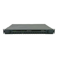
iDirect iconnex e800 Installation And Safety Manual (90 pages)
Brand:
iDirect
| Category:
Network Router
| Size: 1.73 MB
Table of Contents
Table of Contents
3
About this Manual
11
Intended Audience
11
Manual Contents
11
Document Conventions
12
Safety Definitions
12
Table 1. Safety Definitions
12
Disclaimer
13
Iconnex E800 Warranty, Restrictions and Disclaimer
13
Restrictions
13
Disclaimer of Warranty
14
Getting Help
14
Introduction
15
Figure 1. Front View of the E8350 Satellite Router
15
Safety Information
17
Installation Guidelines
17
Electrical Safety
19
Physical and Environmental Considerations
19
Operational and Maintenance Safety
21
Safety Guidelines to Observe During Servicing
21
Servicing
21
Conditions Requiring Service
21
Evolution 8000 Series Specifications
23
E8350 Satellite Router Specifications
23
Mechanical and Environmental Specifications
23
Table 2. E8350 Satellite Router Mechanical and Environmental Specifications
23
Power Specifications
24
Table 3. E8350 Satellite Router Power Specifications
24
RF Specifications
25
Table 4. E8350 Satellite Router RF Specifications
25
Iconnex E800 Satellite Router Specifications
26
Mechanical and Environmental Specifications
26
Table 5. E800 Iconnex Satellite Router Mechanical and Environmental Specifications
26
Power Specifications
27
Table 6. E800 Iconnex Satellite Router Power Specifications
27
RF Specifications
28
Table 7. E800 Iconnex Satellite Router RF Specifications
28
Installing Your E8350 Satellite Router
31
Tools and Supplies Required for Installation
31
Table 8. Recommended Tools
31
Figure 2. Installation Tools
32
Figure 3. DB-9 to RJ-45 Adapter and Connector
32
Unpacking Your E8350 Satellite Router
33
Components Normally Included in an Order
33
Figure 4. Mounting Ears for the Evolution E8350 Satellite Router
33
Additional Components Normally Required
34
Mounting the E8350 Satellite Router
35
General Guidelines for Mounting Configurations
35
Guidelines for Desktop or Shelf Mounting
35
Guidelines for Rack Mounting
35
Defining the E8350 Satellite Router Rear Panel
36
Table 9. E8350 Satellite Router Connectors
37
Table 10. RJ-45 Pin Assignments
37
Figure 8. GPIO/RS-232 Port Pin Numbering
39
Table 11. RS-232 Serial Connector Pin Assignments
39
Preparing the Coax Cables
40
Figure 9. Recommended Tools for Terminating Coaxial Cable
41
Figure 10. Coax Cable Cutting Technique
42
Table 12. Coax Trim Dimensions
42
Figure 11. Cutting Technique for Removing Foil in the Braid
43
Figure 12. Folding the Braid
43
Figure 13. Attaching the RG-11 Connector
44
Figure 14. Crimp Area for F-Type Plugs
44
Console Port Cable Specifications and Pinout
45
Figure 15. Proper Center Connector Length and Crimping Technique
45
Figure 16. Holding the RJ-45 Cable Connectors
46
Table 13. RJ-45 to DB-9 Pinouts
46
Figure 17. RJ-45 to DB-9 Female DTE Adapter
47
Ethernet Port Cable Specifications and Pinouts
48
Connecting AC Power
48
Figure 18. RJ-45 Cable Connectors, Plug and Receptacle
48
Table 14. RJ-45 Connector Pin Assignments
48
Preparing Your Pc/Laptop
49
Checking Conditions before Powering up the System
49
Powering up the System
49
Table 15. LED Status
50
Monitoring LED Status Indicators
51
Front Panel Power and Network LED Status Indicators
51
Front and Rear Panel LED Status Definitions
52
Table 16. Front Panel LED Indicators
52
Maintaining the Remote
53
Table 17. Rear Panel LED Indicators
53
Temperature Control
54
Dust Removal
54
Repacking the E8350 Satellite Router
55
Iconnex E800 Physical Interfaces
57
Iconnex E800 Satellite Router Interface Specifications
57
Power Connectors
59
Table 18. E800 Iconnex Satellite Router Port Specifications
59
Iconnex E800 Satellite Router Remote ON/OFF Switch Connector
60
Iconnex E800 Satellite Router Remote LED Connector
60
Figure 21. JP1 Pin Numbering
60
Figure 22. JP2 Pin Numbering
60
Table 19. JP1 Pin Assignments
60
Table 20. JP2 Connector Pin Assignments
60
Iconnex E800 Satellite Router DC Power Connector
61
Figure 23. JP18 Pin Numbering
61
Table 21. JP18 Pin Assignments
61
Console Port Cables
62
Console Port Pin Assignments
63
Figure 25. RJ-45 to DTE Adapter Pin Identification
63
Figure 26. Console Pin Numbers
63
Table 22. E800 Iconnex Satellite Router Console Pin Assignments
63
LED Status and Definitions
64
Front Edge Status Leds
64
Table 23. Front Panel Leds
64
Rear Panel Status Leds
65
Circuit Board Temperature Monitor
65
Table 24. Rear Panel Leds
65
Configuring the Iconnex E800 as a Mobile Remote
67
What Is a Mobile Remote
67
Hardware Connections for a Mobile Remote
68
Figure 27. Iconnex E800 Hardware Connections Diagram
68
GPS Receiver Specification
69
Iconnex E800 GPS Port Pin Assignments
69
Figure 28. HD-15 Pin Numbers
69
Table 25. HD-15(F) RS-232 Serial Port Pin Assignments
69
Handshake Signals
70
GPS Information
70
Configuring a Mobile Remote
71
Monitoring a Mobile Remote
71
Warnings for the E8350 Satellite Router
73
Danger/Warning Symbol
73
Installation Warning
74
Restricted Area Warning
75
Service Personnel Warning
76
Qualified Personnel Warning
77
Operating Temperature and Airflow Warning
77
Lightning Activity Warning
78
Safety Extra-Low Voltage Port Warning
79
Ground Conductor Warning
80
AC Power Supply Circuit Warning
82
Compliance for the E8350 Satellite Router
83
Figure 29. Evolution 8000 Series Satellite Router Product Label
83
FCC Compliance
84
Part 15 Compliance
84
Canadian Labeling Requirements
84
CE Compliance (European Union)
85
Safety
85
Rohs and WEEE Compliance
86
Compliance with Rohs Directive (2002/95/EC)
86
Compliance with WEEE Directive (2002/96/EC)
86
Declaration of Conformity
87
Advertisement
Related Products
iDirect evolution e150
iDirect evolution e8350
iDirect iconnex e850
iDirect Evolution
iDirect Evolution 8000 Series
iDirect Evolution X3
iDirect evolution x5
iDirect Evolution X7
iDirect iNFINITI 3000
iDirect iNFINITI 5000
iDirect Categories
Network Router
Modem
Receiver
More iDirect Manuals
Login
Sign In
OR
Sign in with Facebook
Sign in with Google
Upload manual
Upload from disk
Upload from URL