Sign In
Upload
Manuals
Brands
ICP DAS USA Manuals
Measuring Instruments
PMD-224 Series
ICP DAS USA PMD-224 Series Manuals
Manuals and User Guides for ICP DAS USA PMD-224 Series. We have
1
ICP DAS USA PMD-224 Series manual available for free PDF download: User Manual
ICP DAS USA PMD-224 Series User Manual (368 pages)
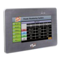
Power Meter Concentrator
Brand:
ICP DAS USA
| Category:
Measuring Instruments
| Size: 10.63 MB
Table of Contents
Table of Contents
3
System Introduction
16
Figure1-1 : System Architecture
17
Before Installation
21
System Login
22
Figure3-1 : PMC/PMD Login Page
22
System Main Page
23
Figure4-1 : Main Page
23
System Function Area
24
Rules Management Toolbar
24
Figure4-2 : System Function Area (Login as a Administrator)
24
Figure4-3 : System Function Area(Login as a General User)
24
Figure4-4 : Rules Management Toolbar (Login as a Administrator)
24
Figure4-5 : Rules Management Toolbar (Login as a General User)
25
Figure4-6 : Confirm to Clear Settings
25
Figure4-7 : Confirm to Load Settings
25
Figure4-8 : Confirm to Save Settings
26
Figure4-9 : Confirm to Logout (the Settings Are Saved)
26
Figure4-10 : Confirm to Logout (the Settings Are Not Saved)
26
Real-Time Information Area
27
System Function Toolbar
27
Figure4-11 : Real-Time Information Area
27
Figure4-12 : Real-Time Information List
27
Sub-Function Area
29
Data Review/System Setting Area
29
Figure4-13 : Current Function Path
29
Figure4-14 : Power Data Overview Page
30
Figure4-15 : Select the Classification of Power Data
30
Figure4-16 : Display Power Data of the Selected Classification
31
Main Page
32
Power Meter Information
32
Power Meter Information Overview
32
Figure5-1 : Information Display Options on Main Page
32
Figure5-2 : Power Meter Information Overview
33
Figure5-3 : the Attribute of PM-3133 Power Meter
34
Figure5-4 : the Attribute of PM-3133-MTCP Power Meter
34
Figure5-5 : Real Time Power Information of PM-3133
34
Figure5-6 : Real Time Power Information of PM-3114
35
Figure5-7 : Real Time Power Information of PM-3112
35
Power Meter Statistics Information Overview
36
Figure5-8 : Power Meter Statistics Information
36
Other Information
37
I/O Information
37
Figure5-9 : Power Meter Other Information Page
37
Figure5-10 : Power Meter I/O Information Page
37
Power Data Information
38
Overview
38
Figure5-11 : Power Data Overview Mode
38
Group Overview
39
Figure5-12 : Change Display List Button
39
Figure5-13 : the Power Meter List
39
Figure5-14 : Power Data Group Overview Mode
39
Realtime Chart
40
Power Meter Mode
40
Figure5-15 : Realtime Chart (Power Meter Mode)
41
Group Mode
42
Figure5-16 : Realtime Chart (Group Mode)
43
Historical Chart
44
Figure5-17 : Historical Chart Inquiry
44
Figure5-18 : Historical Data Chart for Power Data
45
Historical Data Report
46
Figure5-19 : Historical Data Table for Power Data
46
Figure5-20 : Historical Data Report Inquiry
46
Figure5-21 : Daily Report for PM-3133
47
Historical Electricity Analysis
48
Energy Usage Analysis by Trend
48
Figure5-22 : Daily Report for PM-3114
48
Figure5-23 : "Total Accu. Electricity" Report for Power Meters Group
48
Figure5-24 : Energy Usage Analysis by Trend
49
Figure5-25 : Inquiry by Group Mode
50
Figure5-26 : Inquiry by User-Defined Mode
50
Energy Usage Analysis by Time Period
51
Figure5-27 : PM-3114 Energy Usage Analysis Trend Chart
51
Figure5-28 : Energy Usage Analysis by Time Period
52
Energy Usage Breakdown by Circuit/Group
53
Figure5-29 : Time Histogram Chart for PM-3114 Loop 1
53
Figure5-30 : Energy Usage Breakdown by Circuit/Group
53
Figure5-31 : Inquiry by Group Mode
54
Figure5-32 : Energy Usage Breakdown by Circuit/Group Chart
55
PUE Information
56
Real-Time
56
History
56
Figure5-33 : PUE Information - Realtime
56
Figure5-34 : PUE Information - History(1)
57
Figure5-35 : PUE Information - History(2)
57
I/O Information
58
Figure5-36 : I/O Information(Login as Administrator)
58
Figure5-37 : I/O Information(Login as General User)
58
I/O Realtime Chart
59
Figure5-38 : I/O Realtime Chart
59
I/O Historical Chart
60
Figure5-39 : I/O Channel Historical Chart
60
Figure5-40 : User-Defined Historical Chart
60
Figure5-41 : I/O Historical Data Chart
61
Event Log
62
Figure5-42 : Event Log Information Display
62
Polling Time Information
63
Modbus Table Information
63
Figure5-43 : Polling Time Information
63
Figure5-44 : the Interface of Modbus Table Information
63
UID Information
64
Figure5-45 : Inquiry Result of Modbus Table Information
64
Ping Status Page
65
Figure5-46 : Power Meter UID Information Page
65
Figure5-47 : Ping Status Page
65
System Setting
66
Figure6-1 : System Setting Overview Page
66
Time Setting
67
Figure6-2 : Time Setting Page
67
Figure6-3 : Time Synchronization Setting
68
Network Setting
69
Figure6-4 : Network Setting Page
69
Figure6-5 : Signal Strength Level and IP Address for Mobile Network
71
Figure6-6 : DDNS Setting Page
71
Figure6-7 : Iotstar Connection Setting Page(1)
73
Figure6-8 : Iotstar Connection Setting Page(1)
74
SNMP Setting
75
Figure6-9 : SNMP Setting Page
75
Figure6-10 : SNMP Manager List
76
Figure6-11 : the Address Setting for SNMP Manager
76
Figure6-12 : the Working Model Setting for SNMP Manager
76
Figure6-13 : Save the SNMP Manager Setting
77
Security Setting
78
Figure6-14 : Security Setting Page
78
Figure6-15 : Password Setting Page
79
Figure6-16 : Local FTP Server Setting Page
79
I/O Interface Setting
80
Figure6-17 : Idle Time Setting Page
80
Figure6-18 : I/O Interface Setting Page
80
Figure6-19 : Function Setting to Connect to HMI or SCADA
81
Figure6-20 : Function Setting to Connect to Modbus RTU Slave Device
82
Other Setting
83
Figure6-21 : I/O Function Setting about LAN
83
Figure6-22 : Other Setting Page
84
Power Meter Group Setting
86
Group and Subgroup Viewing
86
Group and Subgroup Setting
86
Figure6-23 : Power Meter Group Setting
86
Figure6-24 : Group and Subgroup Viewing
86
Figure6-25 : Group Setting
87
Figure6-26 : Subgroup Setting
87
Figure6-27 : Subgroup Setting Window
87
Group and Subgroup Configuration
88
Setup the Loops/Phases of the Subgroup
88
Figure6-28 : Configurations for Subgroup
88
Figure6-29 : Loops/Phases of Subgroup Setting
89
Figure6-30 : Choose Loops/Phased of Subgroup
89
Loop/Phase of Group Configuration
90
Figure6-31 : Add Loops/Phases for Subgroup
90
Figure6-32 : Configurations for Loops/Phased of Subgroup
90
Firmware Update
91
Figure6-33 : Firmware Update(1)
91
Figure6-34 : Firmware Update(2)
92
Figure6-35 : Firmware Update(3)
92
Figure6-36 : Firmware Update(4)
92
Rule File Import & Export
93
Figure6-37 : Firmware Update(5)
93
Figure6-38 : Firmware Update(6)
93
Figure6-39 : Export / Import Setting Page and the Settings to be Backed up
94
Power Meter & I/O Module Setting
96
Figure7-1 : Meter / Module Setting Page
96
Power Meter Setting
97
Figure7-2 : Power Meter Setting Page
97
Scan to Add Modbus RTU Power Meters
98
Figure7-3 : the "Scan" Button to Search Power Meter
98
Figure7-4 : Set up the Scanning Range for the Power Meters
98
Add Modbus RTU Power Meter Manually
99
Figure7-5 : Scanning the Power Meters
99
Figure7-6 : the Power Meter List after Scan Operation
99
Figure7-7 : Select the Actual Power Meter Connected to PMC/PMD
99
Figure7-8 : Set up the no and Address of the Power Meter
100
Figure7-9 : Select Modbus RTU Power Meter Model
100
Add Modbus TCP Power Meter Manually
101
Figure7-10 : Add the Modbus RTU Power Meter Manually
101
Figure7-11 : Add Modbus TCP Power Meter
101
Figure7-12 : Select Modbus TCP Power Meter Model
101
Power Meter List Interface
102
Figure7-13 : Add the Modbus TCP Power Meter Manually
102
Figure7-14 : Power Meter List Interface
102
Modbus RTU Power Meter Setting
103
Figure7-15 : PM-3133 Setting Page
104
Figure7-16 : PM-3114 Setting Page
105
Modbus TCP Power Meter Setting
106
Figure7-17 : PM-3114-MTCP Setting Page
106
XV-Board Setting (PMD Series Does Not Support this Function.)
109
XV-Board DI Channel Settings
109
Figure7-18 : XV-Board Setting Page
109
XV-Board DO Channel Settings
110
Figure7-19 : XV-Board DI Attribute Setting Page
110
Figure7-20 : XV-Board DO Attribute Setting Page
111
XV-Board AI Channel Settings
112
Figure7-21 : XV-Board AI Attribute Setting Page
112
Figure7-22 : AI Deadband Operation(> or >= a Numerical Value)
113
Figure7-23 : AI Deadband Operation(< or <= a Numerical Value)
114
Figure7-24 : AI Deadband Operation(= a Numerical Value)
114
XV-Board AO Channel Settings
115
Figure7-25 : XV-Board AO Attribute Setting Page
115
I/O Module Setting
116
Figure7-26 : I/O Module Setting Page
116
Scan to Add ICP das M-7000/DL Modules
117
Figure7-27 : the "Scan" Button to Search M-7000/DL Module
117
Figure7-28 : Set up the Scanning Range for the M-7000/DL Module
117
Figure7-29 : Scanning the M-7000/DL Modules
118
Figure7-30 : the M-7000/DL List after Scan Operation
118
Figure7-31 : Select the Actual M-7000/DL Modules Connected to PMC/PMD
118
Add Modbus RTU Module (or M-7000/DL/IR Module) Manually
119
Figure7-32 : Set up the no and Address of the Modbus RTU Module
119
Figure7-33 : Select the Model of the Modbus RTU Module
119
Add Modbus TCP Module Manually
120
Figure7-34 : Add the Modbus RTU Module Manually
120
Figure7-35 : Add Modbus TCP Module
120
I/O Module List Interface
121
Figure7-36 : Add the Modbus RTU Power Meter Manually
121
Figure7-37 : Modbus Module List Interface
121
M-7000/DL/IR Module Setting
122
Figure7-38 : M-7000 DI Channel Setting Page
123
Figure7-39 : M-7000/DL DO Channel Setting Page
124
Figure7-40 : M-7000/DL AI Channel Setting Page
126
Modbus RTU Module Setting
127
Figure7-41 : M-7000 AO Channel Setting Page
127
Figure7-42 : Modbus RTU Slave Module Setting Page
128
Figure7-43 : Coil Output Setting Page
129
Figure7-44 : Coil Output Setting Example for Modbus RTU Module
130
Figure7-45 : Discrete Input Setting Page
131
Figure7-46 : Discrete Input Setting Example for Modbus RTU Module
132
Figure7-47 : Input Register Setting Page
134
Figure7-48 : Input Register Setting Example for Modbus RTU Module
135
Figure7-49 : Holding Register Setting Page
137
Modbus TCP Module Setting
139
Figure7-50 : Input Register Setting Example for Modbus RTU Module
139
Figure7-51 : Modbus TCP Slave Module Setting Page(1)
140
Figure7-52 : Modbus TCP Slave Module Setting Page(2)
141
Logger Setting
142
Figure8-1 : Data Logger Setting Page
142
Data Logger Setting
143
Figure8-2 : Data Logger Setting Page
143
Event Logger Setting
146
Figure8-3 : Event Logger Setting Page
146
FTP Upload Setting
147
Figure8-4 : FTP Upload Setting Page
147
Report Sending Setting Page
149
Sending Setting
149
Re-Send Function
149
Figure8-5 : Report Sending Setting Page - Sending Setting
149
Figure8-6 : Report Sending Setting Page - Sending Setting
150
The Path of Data Log File
151
The Format of the Power Data Logger File
153
The Format of the Power Report File
154
The Format of I/O Data File
158
The Format of User-Defined Data File
158
Iot Platform Setting
159
Microsoft Azure Setting
160
Figure9-1 : Microsoft Azure Setting Page
160
Figure9-2 : Microsoft Azure Publish Message Setting Page
161
Figure9-3 : "User-Defined Data" Setting Interface of Iot Platform
162
Figure9-4 : Microsoft Azure Subscribe Topic Setting Page
163
IBM Bluemix Setting
164
Figure9-5 : IBM Bluemix Setting Page
164
Figure9-6 : IBM Bluemix Subscribe Message Setting Page
165
MQTT Setting
166
Broker Setting
166
Figure9-7 : MQTT Setting Page (Broker)
167
Figure9-8 : MQTT Broker Parameter Setting Page
167
Figure9-9 : Publish Message and Subscribe Topic Setting Page
169
Figure9-10 : Publish Message Setting Page
170
Topic Import/Export Setting
172
Figure9-11 : Subscribe Topic Setting Page
172
Figure9-12 : MQTT Topic Import/Export Setting Page
173
Figure9-13 : the Export of MQTT Topic
173
Iotstar Real-Time Data Sending Setting
174
Figure9-14 : the Import of MQTT Topic
174
Figure9-15 : Iotstar Real-Time Data Sending Setting Page
174
Iotstar Historical Data Sending Setting
175
Iotstar Bot Service Setting
176
Advanced Setting
178
Email Setting
178
Figure10-1 : Email Setting Page
179
Figure10-2 : Email Setting Page(Name & Description))
179
Figure10-3 : Email Setting Page(SMTP Server)
180
Figure10-4 : Email Setting Page(Email Address)
180
Figure10-5 : Email Setting Page(Email Content)
181
SMS Setting
182
SMS Alarm Setting
182
Figure10-6 : SMS Setting Page (1)
182
Figure10-7 : SMS Setting Page (2)
183
SMS Command Setting
184
Figure10-8 : SMS Command Setting Page (1)
184
Figure10-9 : SMS Command Setting for GET Command
186
Figure10-10 : SMS Command Setting for SET Command
186
Figure10-11 : SMS Command List
186
SNMP Trap Setting
188
Figure10-12 : SNMP Trap Setting Page
188
Figure10-13 : SNMP Trap Parameter Setting Page
188
Figure10-14 : "Channel Data"Type Setting Page
189
Figure10-15 : Example of "Channel Data" Type Variable Binding List
190
Figure10-16 : "User-Defined Data" Type Setting Page
190
Figure10-17 : "User-Defined Data" Interface in Edit Mode
191
Figure10-18 : "User-Defined Data" Interface in View Mode
192
Figure10-19 : SNMP Trap Setting with Variable Bindings List
192
LINE Notify Setting
193
Message Setting
193
Figure10-20 : LINE Notify Message Setting Page (1)
193
Figure10-21 : LINE Notify Message Setting Page (2)
194
Figure10-22 : LINE Notify Message Setting Page (3)
194
Chat Room Setting
195
Figure10-23 : LINE Notify Message Setting Page (4)
195
Figure10-24 : LINE Notify Chat Room Setting Page (1)
196
Figure10-25 : LINE Notify Chat Room Setting Page (2)
196
Figure10-26 : LINE Notify Chat Room Setting Page (3)
197
Figure10-27 : LINE Notify Chat Room Setting Page (4)
197
Figure10-28 : LINE Notify Chat Room Setting Page (5)
197
Timer Setting
198
Figure10-29 : Timer Creating Page
199
Figure10-30 : Timer Setting Page(Assign Period)
199
Schedule Setting
200
Figure10-31 : Timer Setting Page(Internal Register)
200
Figure10-32 : Schedule Setting Page
200
Figure10-33 : Calendar Mode of Schedule Setting
201
Figure10-34 : Repeat Mode of Schedule Setting
202
PUE Setting
204
Figure10-35 : PUE Setting Page(1)
204
Figure10-36 : PUE Setting Page(2)
205
Internal Register Setting
206
Figure10-37 : Internal Register Setting Page(1)
206
Figure10-38 : Internal Register Setting Page(2)
207
Ping Setting
208
Figure10-39 : Ping List Page
208
Figure10-40 : Ping List Page
209
Rules Setting
210
Figure11-1 : Rules Overview Page
210
Figure11-2 : Rules Setting Page
211
IF Condition Setting
212
ICP das Module
213
Figure11-3 : DI Condition Setting Page
213
Figure11-4 : DI Counter Condition Setting Page
214
Figure11-5 : AI Condition Setting Page
217
Modbus Module
218
Figure11-6 : Discrete Input Condition Setting Page
218
Figure11-7 : Coil Output Condition Setting Page
219
Figure11-8 : Input Register Condition Setting Page
219
Figure11-9 : Holding Register Condition Setting Page
220
Power Meter
221
Figure11-10 : Power Meter Condition Setting Page
221
Microsoft Azure
222
Figure11-11 : Microsoft Azure Connection Status Condition Setting
222
Figure11-12 : Microsoft Azure Subscribe Message Condition Setting
222
IBM Bluemix
223
Figure11-13 : IBM Bluemix Connection Status Condition Setting
223
Mqtt
224
Figure11-14 : IBM Bluemix Subscribe Message Condition Setting
224
Figure11-15 : Broker Connection Status Condition Setting
225
Figure11-16 : Subscribe Topic Condition Setting
225
Connection Status
226
Timer
226
Figure11-17 : Connection Status Condition Setting Page
226
Figure11-18 : Timer Condition Setting Page
226
Schedule
227
Mobile Network Signal Strength
227
Figure11-19 : Schedule Condition Setting Page
227
FTP Upload Status
228
SD Card Status
228
Figure11-20 : Mobile Network Signal Strength Condition Setting Page
228
Figure11-21 : FTP Upload Status Condition Setting Page
228
Rule Status
229
Internal Register
229
Figure11-22 : SD Card Status Condition Setting Page
229
Figure11-23 : Rule Status Condition Setting Page
229
Pue
230
Figure11-24 : Internal Register Condition Setting Page
230
Figure11-25 : PUE Condition Setting Page
230
Ping
231
Figure11-26 : Ping Condition Setting Page
231
THEN/ELSE Action Setting
232
ICP das Module
233
Figure11-27 : DI Counter Action Setting Page
233
Figure11-28 : DO Action Setting Page
234
Figure11-29 : AO Action Setting Page
234
Modbus Module
238
Figure11-30 : Coil Output Action Setting Page
238
Power Meter
239
Figure11-31 : Holding Register Action Setting Page
239
Microsoft Azure
240
Figure11-32 : Power Meter Relay Action Setting Page
240
Figure11-33 : Microsoft Azure Function Status Action Setting
240
Figure11-34 : Microsoft Azure Publish Message Action Setting
241
Figure11-35 : Microsoft Azure Reset Variable Action Setting Page
241
IBM Bluemix
242
Figure11-36 : IBM Bluemix Function Status Action Setting
242
Mqtt
243
Figure11-37 : IBM Bluemix Publish Message Action Setting
243
Figure11-38 : IBM Bluemix Reset Variable Action Setting Page
243
Figure11-39 : Broker Function Action Setting Page
244
Figure11-40 : Publish Message Action Setting Page
244
Timer
245
Figure11-41 : MQTT Reset Topic Action Setting Page
245
Email
246
Figure11-42 : Timer Action Setting Page
246
Figure11-43 : Email Action Setting Page
246
SMS Alarm
247
SNMP Trap
247
Figure11-44 : SMS Alarm Action Setting Page
247
LINE Notify
248
Figure11-45 : SNMP Trap Action Setting Page
248
Figure11-46 : LINE Notify Action Setting Page
248
Bot Service
249
Re-Boot System
249
Reset Modem
249
Figure11-47 : Bot Service Action Setting Page
249
Figure11-48 : Re-Boot System Action Setting Page
249
Data Logger
250
Rule Status
250
Figure11-49 : Reset Modem Action Setting Page
250
Figure11-50 : Data Logger Action Setting Page
250
Internal Register
251
Figure11-51 : Rule Status Action Setting Page
251
Figure11-52 : Internal Register Action Setting Page
251
Appendix I:modbus Address Table
253
Advertisement
Advertisement
Related Products
ICP DAS USA PMD series
ICP DAS PMD-4201
ICP DAS PMD-2201
ICP DAS USA PMD-523 Series
ICP DAS USA PM-3133i
ICP DAS USA PMC-523 Series
ICP DAS USA PM-3133-MTCP
ICP DAS USA PM-4324-100P-CPS
ICP DAS USA PM-4324-240P-MTCP
ICP DAS USA PM-4324A-MTCP
ICP DAS USA Categories
Control Unit
I/O Systems
Controller
Media Converter
PCI Card
More ICP DAS USA Manuals
Login
Sign In
OR
Sign in with Facebook
Sign in with Google
Upload manual
Upload from disk
Upload from URL