Sign In
Upload
Manuals
Brands
Fujitsu Manuals
Storage
ETERNUS DX60 S4
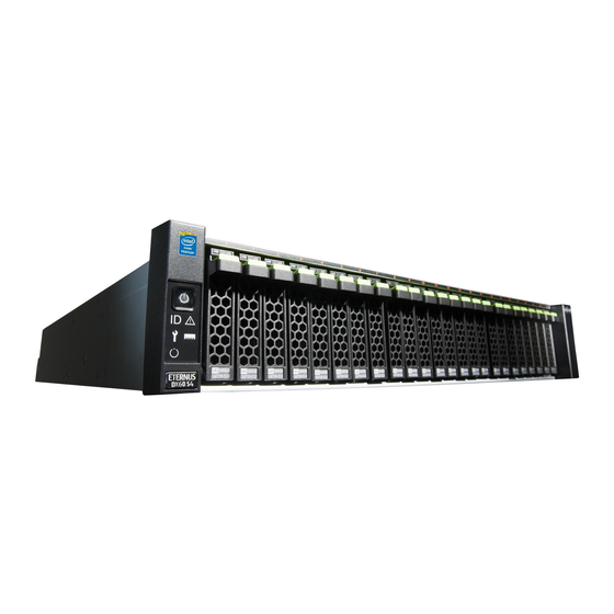
Fujitsu ETERNUS DX60 S4 Manuals
Manuals and User Guides for Fujitsu ETERNUS DX60 S4. We have
5
Fujitsu ETERNUS DX60 S4 manuals available for free PDF download: Design Manual, Operation Manual, Configuration Manual, Safety Precautions
Fujitsu ETERNUS DX60 S4 Design Manual (149 pages)
Hybrid Storage Systems
Brand:
Fujitsu
| Category:
Storage
| Size: 3.19 MB
Table of Contents
Table of Contents
2
1 Function
12
Table 1 Basic Functions
12
RAID Functions
13
Supported RAID
13
Figure 1 RAID0 Concept
14
Figure 2 RAID1 Concept
14
Figure 3 RAID1+0 Concept
15
Figure 4 RAID5 Concept
15
Figure 5 RAID5+0 Concept
16
Figure 6 RAID6 Concept
17
Figure 7 RAID6-FR Concept
18
Table 2 RAID Level Comparison
18
User Capacity (Logical Capacity)
19
Table 3 Formula for Calculating User Capacity for each RAID Level
19
Table 4 User Capacity Per Drive
20
RAID Group
21
Figure 8 Example of a RAID Group
21
Table 5 RAID Group Types and Usage
21
Volume
22
Figure 9 Volume Concept
22
Table 6 Recommended Number of Drives Per RAID Group
22
Table 7 Volumes that Can be Created
23
Hot Spares
24
Figure 10 Hot Spares
24
Table 8 Hot Spare Selection Criteria
25
Data Protection
26
Data Block Guard
26
Figure 11 Data Block Guard
26
Disk Drive Patrol
28
Figure 12 Disk Drive Patrol
28
Redundant Copy
29
Figure 13 Redundant Copy Function
29
Rebuild
30
Figure 14 Rebuild
30
Fast Recovery
31
Figure 15 Fast Recovery
31
Copyback/Copybackless
32
Figure 16 Copyback
32
Figure 17 Copybackless
33
Protection (Shield)
34
Figure 18 Protection (Shield)
34
Reverse Cabling
35
Figure 19 Reverse Cabling
35
Operations Optimization (Virtualization)
36
Thin Provisioning
36
Figure 20 Storage Capacity Virtualization
36
Table 9 TPP Maximum Number and Capacity
37
Table 10 Chunk Size According to the Configured TPP Capacity
37
Table 11 Levels and Configurations for a RAID Group that Can be Registered in a TPP
37
Table 12 TPP Thresholds
38
Table 13 TPV Thresholds
38
Figure
38
Figure 21 TPV Balancing (When Allocating Disproportionate TPV Physical Capacity Evenly)
39
Figure 22 TPV Balancing (When Distributing Host Accesses Evenly after TPP Expansion)
39
Figure 23 TPV Capacity Optimization
41
Optimization of Volume Configurations
42
Table 14 Optimization of Volume Configurations
42
Figure 24 RAID Migration (When Data Is Migrated to a High Capacity Drive)
44
Figure 25 RAID Migration (When a Volume Is Moved to a Different RAID Level)
44
RAID Migration
44
Figure 26 Logical Device Expansion (When Expanding the RAID Group Capacity)
45
Logical Device Expansion
45
Figure 27 Logical Device Expansion (When Changing the RAID Level)
46
Figure 28 LUN Concatenation
47
Figure 29 LUN Concatenation (When the Concatenation Source Is a New Volume)
47
LUN Concatenation
47
Figure 30 LUN Concatenation (When the Existing Volume Capacity Is Expanded)
48
Figure 31 Wide Striping
49
Wide Striping
49
User Access Management
50
Account Management
50
Figure 32 Account Management
50
Table 15 Available Functions for Default Roles
51
User Authentication
52
Table 16 Client Public Key (SSH Authentication)
52
Audit Log
54
Figure 33 Audit Log
54
Improving Host Connectivity
55
Host Affinity
55
Figure 34 Host Affinity
55
Figure 35 Associating Host Groups, CA Port Groups, and LUN Groups
56
Iscsi Security
57
Environmental Burden Reduction
58
Eco-Mode
58
Figure 36 Eco-Mode
58
Table 17 Eco-Mode Specifications
59
Power Consumption Visualization
61
Figure 37 Power Consumption Visualization
61
Operation Management/Device Monitoring
62
Operation Management Interface
62
Table 18 ETERNUS Web GUI Operating Environment
62
Performance Information Management
63
Event Notification
65
Figure 38 Event Notification
65
Table 19 Levels and Contents of Events that Are Notified
65
Table 20 SNMP Specifications
66
Device Time Synchronization
68
Figure 39 Device Time Synchronization
68
Power Control
69
Power Synchronized Unit
69
Figure 40 Power Synchronized Unit
69
Remote Power Operation (Wake on LAN)
70
Figure 41 Wake on LAN
70
Backup (Advanced Copy)
71
Figure 42 Example of Advanced Copy
71
Table 21 Control Software (Advanced Copy)
71
Backup
72
Table 22 List of Functions (Copy Methods)
72
Table 23 Characteristics of Snapopc/Snapopc+ Operations with each Type of Copy Destination Logical Volume
73
Figure 43 Restore OPC
74
Figure 44 EC Reverse
74
Figure 45 Targets for the Multi-Copy Function
75
Figure 46 Multi-Copy
75
Figure 47 Multi-Copy (Including Snapopc+)
76
Figure 48 Cascade Copy
77
Table 24 Available Cascade Copy Combinations (When a Cascade Copy Performs Session 1 Followed by Session 2)
77
Table 25 Available Cascade Copy Combinations (When a Cascade Copy Performs Session 2 Followed by Session 1)
78
Performance Tuning
80
Striping Size Expansion
80
Table 26 Available Stripe Depth
80
Assigned Cms
81
Figure 49 Assigned Cms
81
Stable Operation Via Load Control
82
Host Response
82
Figure 50 Host Response
82
Data Migration
83
Storage Migration
83
Figure 51 Storage Migration
83
Figure 52 Non-Disruptive Storage Migration
85
Non-Disruptive Storage Migration
85
Table 27 Specifications for Paths and Volumes between the Local Storage System and the External Storage System
85
Server Linkage Functions
87
Oracle VM Linkage
87
Figure 53 Oracle VM Linkage
87
Vmware Linkage
88
Figure 54 Vmware Linkage
88
Veeam Storage Integration
90
Figure 55 Veeam Storage Integration
90
Table 28 Volume Types that Can be Used with Veeam Storage Integration
91
Microsoft Linkage
92
Figure 56 Microsoft Linkage
92
Openstack Linkage
94
Logical Volume Manager (LVM)
95
Figure 57 Logical Volume Manager (LVM)
95
Smart Setup Wizard
96
Table 29 Guideline for the Number of Drives and User Capacities (When 1.92TB Ssds Are Installed)
96
Figure 58 RAID Configuration Example (When 12 Ssds Are Installed)
99
Table 30 Guideline for the Number of Drives and User Capacities (When 1.2TB SAS Disks Are Installed)
99
Figure 59 RAID Configuration Example (When 15 SAS Disks Are Installed)
101
2 Connection Configuration
102
SAN Connection
102
Host Interface
102
Table 31 Ethernet Frame Capacity (Jumbo Frame Settings)
103
Access Method
105
Figure 60 Single Path Connection (When a SAN Connection Is Used - Direct Connection)
105
Figure 61 Single Path Connection (When a SAN Connection Is Used - Switch Connection)
105
Figure 62 Multipath Connection (When a SAN Connection Is Used - Basic Connection Configuration)
106
Figure 63 Multipath Connection (When a SAN Connection Is Used - Switch Connection)
106
LAN Connection
107
LAN for Operation Management (MNT Port)
107
Figure 64 Connection Example Without a Dedicated Remote Support Port
108
Figure 65 Connection Example When the IP Address of the Slave CM Is Set
108
LAN for Remote Support (RMT Port)
109
Figure 66 Overview of the AIS Connect Function
109
Figure 67 Security Features
110
Figure 68 Connection Example with a Dedicated Remote Support Port
111
LAN Control (Master CM/Slave CM)
112
Figure 69 Connection Example When the IP Address of the Slave CM Is Set
112
Figure 70 LAN Control (Switching of the Master CM)
113
Figure 71 LAN Control (When the IP Address of the Slave CM Is Set)
113
Network Communication Protocols
114
Table 32 LAN Port Availability
114
Power Supply Connection
116
Input Power Supply Lines
116
UPS Connection
116
Power Synchronized Connections
117
Power Synchronized Connections (PWC)
117
Figure 72 Power Supply Control Using a Power Synchronized Unit (When Connecting One or Two Servers)
117
Figure 73 Power Supply Control Using a Power Synchronized Unit (When Connecting Three or more Servers)
119
Power Synchronized Connections (Wake on LAN)
120
Figure 74 Power Supply Control Using Wake on LAN
120
3 Hardware Configurations
121
Configuration Schematics
122
Figure 75 Minimum Configuration Diagram: ETERNUS DX60 S4
122
Figure 76 Minimum Configuration Diagram: ETERNUS DX60 S3
123
Figure 77 Maximum Configuration Diagram: ETERNUS DX60 S4
124
Figure 78 Maximum Configuration Diagram: ETERNUS DX60 S3
126
Figure 79 Enclosure Connection Path (When Only One Controller Is Installed)
128
Figure 80 Enclosure Connection Path (When Two Controllers Are Installed)
128
Optional Product Installation Conditions
129
Controller Module
129
Drive Enclosures
130
I/O Module
130
Drives
131
Table 33 Drive Characteristics
132
Table 34 Number of Installable Drives
133
Standard Installation Rules
134
Controller Module
134
Drive Enclosure
134
Figure 81 Controller Installation Order
134
I/O Module
135
Drive
135
Figure 82 I/O Module Installation Order
135
Figure 83 Installation Diagram for 2.5" Drives
136
Figure 84 Installation Diagram for 3.5" Drives
136
Recommended RAID Group Configurations
137
Figure 85 Drive Combination 1
137
Figure 86 Drive Combination 2
137
Figure 87 Drive Combination 3
138
Figure 88 Drive Combination 4
139
Figure 89 Drive Combination 5
139
4 Maintenance/Expansion
140
Hot Swap/Hot Expansion
140
Table 35 Hot Swap and Hot Expansion Availability for Components (ETERNUS DX60 S4)
140
Table 36 Hot Swap and Hot Expansion Availability for Components (ETERNUS DX60 S3)
141
User Expansion
142
SSD Sanitization
142
Function Specification List
143
List of Supported Protocols
143
Table 37 List of Supported Protocols
143
Target Pool for each Function/Volume List
144
Target RAID Groups/Pools of each Function
144
Target Volumes of each Function
144
Combinations of Functions that Are Available for Simultaneous Executions
146
Table 38 Combinations of Functions that Can be Executed Simultaneously (1/2)
146
Table 39 Combinations of Functions that Can be Executed Simultaneously (2/2)
146
Number of Processes that Can be Executed Simultaneously
147
Advertisement
Fujitsu ETERNUS DX60 S4 Operation Manual (88 pages)
Hybrid Storage Systems
Brand:
Fujitsu
| Category:
Storage
| Size: 3.51 MB
Table of Contents
Table of Contents
2
1 Component Names and LED Names
9
Controller Enclosures
9
Front
9
Figure 1 Front View of a 2.5" Type Controller Enclosure
9
Figure 2 Front View of a 3.5" Type Controller Enclosure
9
Rear
10
Figure 3 Rear View of a Controller Enclosure (When Only One Controller Is Installed)
10
Figure 4 Rear View of a Controller Enclosure (When Two Controllers Are Installed)
10
Components (Front)
11
Figure 5 Operation Panel (Controller Enclosure)
11
Table 1 Status and Meanings of each LED (Operation Panel (Controller Enclosure))
11
Figure 6 2.5" Drives
13
Figure 7 Drive Slot Numbers (2.5" Type Controller Enclosure)
13
Figure 8 3.5" Drives
13
Figure 9 Drive Slot Numbers (3.5" Type Controller Enclosure)
13
ETERNUS DX60 S4 Components (Rear)
14
Figure 10 Controllers
14
Table 2 Status and Meanings of each LED (Drive (Controller Enclosure))
14
Table 3 Status and Meanings of each LED (Controller)
16
ETERNUS DX60 S3 Components (Rear)
17
Figure 11 Power Supply Unit (Controller Enclosure)
17
Table 4 Status and Meanings of each LED (Power Supply Unit (Controller Enclosure))
17
Figure 12 Controllers
18
Table 5 Status and Meanings of each LED (Controller)
19
Figure 13 Power Supply Unit (Controller Enclosure)
21
Table 6 Status and Meanings of each LED (Power Supply Unit (Controller Enclosure))
21
Drive Enclosures
22
Front
22
Figure 14 Front View of a 2.5" Type Drive Enclosure
22
Figure 15 Front View of a 3.5" Type Drive Enclosure
22
Rear
23
Figure 16 Rear View of a Drive Enclosure (When Only One I/O Module Is Installed)
23
Figure 17 Rear View of a Drive Enclosure (When Two I/O Modules Are Installed)
23
Components (Front)
24
Figure 18 Operation Panel (Drive Enclosure)
24
Table 7 Status and Meanings of each LED (Operation Panel (Drive Enclosure))
24
Figure 19 2.5" Drives
25
Figure 20 Drive Slot Numbers (2.5" Type Drive Enclosure)
25
Figure 21 3.5" Drives
25
Figure 22 Drive Slot Numbers (3.5" Type Drive Enclosure)
25
Components (Rear)
26
Figure 23 I/O Module
26
Table 8 Status and Meanings of each LED (Drive (Drive Enclosure))
26
Table 9 Status and Meanings of each LED (I/O Module)
26
Figure 24 Power Supply Unit (Drive Enclosure)
28
Table 10 Status and Meanings of each LED (Power Supply Unit (Drive Enclosure))
28
Power Distribution Units (for Regions Other than the EMEIA, Central American, and Caribbean Re- Gions)
29
Power Distribution Units (1U)
29
Figure 25 Power Distribution Unit (AC200-240V, 1U, 4 Outlets)
29
Figure 26 Power Distribution Unit (AC200-240V, 1U, 4 Outlets)
29
Power Distribution Units (2U)
30
Figure 27 Power Distribution Unit (AC200-240V, 2U, 12 Outlets)
30
Figure 28 Power Distribution Unit (AC200-240V, 2U, 16 Outlets)
30
Figure 29 Power Distribution Unit (AC200-240V, 2U, 16 Outlets)
31
2 Basic Operation
32
Powering on and off
32
Switching on and off the Main Line Switch on the Power Distribution Unit (for Regions Other than the EMEIA, Central American, and Caribbean Regions)
32
Figure 30 on Position (Marked "|") of the Main Line Switches on a 1U Power Distribution Unit
32
Figure 31 on Position of the Main Line Switches on a 1U Power Distribution Unit
32
Figure 32 on Position (Marked "|") of the Main Line Switches on a 2U Power Distribution Unit
33
Figure 33 on Position of the Main Line Switches on a 2U Power Distribution Unit
33
Figure 34 off Position (Marked "¡") of the Main Line Switches on a 1U Power Distribution Unit
34
Figure 35 off Position of the Main Line Switches on a 1U Power Distribution Unit
34
Figure 36 off Position (Marked "¡") of the Main Line Switches on a 2U Power Distribution Unit
35
Figure 37 off Position of the Main Line Switches on a 2U Power Distribution Unit
35
Switching on and off the PSU Switch on the Power Supply Unit
36
Figure 38 on Position (Marked "|") of the PSU Switch on a Power Supply Unit
36
Figure 39 off Position (Marked "¡") of the PSU Switch of a Power Supply Unit
37
Powering on
38
Powering off
39
Using the FUNCTION Button
41
3 Storage System Monitoring
43
Checking LED Status
43
Displaying Status Via ETERNUS Web GUI
43
Figure 40 ETERNUS Web GUI Screen
43
Table 11 General Status of ETERNUS Web GUI
43
Displaying Status Via ETERNUS CLI
44
Event Notification
44
Table 12 General Status of ETERNUS CLI
44
Audit Log
45
Figure 41 Event Notification
45
Figure 42 Audit Log
46
4 Component Expansion/Function Enhancement
47
Installing Additional Drives
47
Installable Drives
47
Drive Handling Instructions
47
Additional Drive Installation Procedure
48
Installing Additional Drive Enclosures
54
Installable Drive Enclosures
54
Drive Enclosure Handling Instructions
54
Additional Drive Enclosure Installation Procedure
56
Adding Servers
69
RAID Group Creation
69
Volume Creation
70
Connection Setup
71
5 Maintenance
76
Periodic Backup
76
Maintenance Service
76
Maintenance Support Period
76
Replacing Batteries
76
Related Service
77
6 Troubleshooting
78
Check List
78
Required Information for Inquiries
86
Fujitsu ETERNUS DX60 S4 Configuration Manual (78 pages)
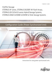
Hybrid Storage Systems / Disk Storage Systems / All-Flash Arrays, ETERNUS DX S4 Series, ETERNUS DX S3 Series. ETERNUS AF Series
Brand:
Fujitsu
| Category:
Storage
| Size: 1.6 MB
Table of Contents
Using this Manual
3
Compliance with Standards
4
About this Manual
6
Symbols Used in this Manual
8
Safety Precautions
9
Table of Contents
17
Chapter 1 Overview
21
External View
21
Figure 1.1 External View of a Power Synchronized Unit
21
Figure 1.2 External View of an AC Sensor Unit
21
Features
22
Specifications
23
Table 1.1 Specifications
23
Components
24
Power Synchronized Unit
24
Figure 1.3 Components (Power Synchronized Unit)
24
Table 1.2 Status and Meanings of each LED (for Power Synchronized Units)
25
AC Sensor Unit (Optional)
26
Figure 1.4 Components (AC Sensor Unit)
26
Table 1.3 Status and Meanings of each LED (for AC Sensor Units)
26
System Configuration
27
Figure 1.5 System Configuration Example (Power Synchronization with Two Server UPS Units)
27
Figure 1.6 System Configuration Example (Power Synchronization with Three or more Server UPS Units)
28
Power Management for Power Synchronization
29
Figure 1.7 Power on Using a Power Synchronized Unit
29
Figure 1.8 Operation Timing Chart When Using a Power Synchronized Unit (Powering On)
30
Figure 1.9 Power off Using a Power Synchronized Unit
31
Figure 1.10 Operation Timing Chart When Using a Power Synchronized Unit (Powering Off)
32
Chapter 2 Installation
33
Package Contents Check
33
Table 2.1 List of Package Contents (Power Synchronized Unit)
33
Table 2.2 List of Package Contents (AC Sensor Unit)
33
Preparation
34
Installation Area
34
Checking Power Sockets and Server UPS Unit Outlets
34
Preparing Power Cords
34
Installing in a Rack
35
Installing a Power Synchronized Unit
36
Installing an AC Sensor Unit
39
Chapter 3 Powering on and off
43
Chapter 4 Connection and Settings
44
Setting the ETERNUS DX/AF
45
Figure 4.1 ETERNUS DX60 S4/DX100 S4/DX200 S4, ETERNUS DX500 S4/DX600 S4
45
Figure 4.2 ETERNUS DX8700 S3/DX8900 S3 Setup (Setup Power Management Screen)
47
Figure 4.3 ETERNUS DX80 S2/DX90 S2 Setup (Setup Power Management Screen)
48
Figure 4.4 ETERNUS DX60 S2 Setup (Setup Power Management Screen)
49
Turning on the Power Synchronized Unit
50
Connecting Cascade Cables
53
Figure 4.5 Cascade Cable Connection
53
Connecting to the Server UPS Unit
56
Figure 4.6 Connection for the Server UPS Units and the AC Sensor Units
56
Connecting the Server UPS Unit to the Power Synchronized Unit
57
Connecting the AC Sensor Unit
58
Connecting to the ETERNUS DX/AF
61
Checking after Connection
64
Chapter 5 Adding a Connecting Device
65
Connection Procedure When Adding a Server
65
Connection Procedure When Adding an ETERNUS DX/AF
67
Chapter 6 Operation and Maintenance
71
Checking the Power Synchronized Unit Status
71
Device Replacement after Operation Startup
71
Replacing a Server
71
Replacing a Power Synchronized Unit
72
Replacing an AC Sensor Unit
72
Troubleshooting
73
Check List
73
Trouble Record
76
Figure 6.1 Trouble Record
76
Advertisement
Fujitsu ETERNUS DX60 S4 Configuration Manual (75 pages)
All-Flash Arrays, Hybrid Storage Systems, Disk Storage Systems, Power Synchronized Unit
Brand:
Fujitsu
| Category:
Storage
| Size: 4 MB
Table of Contents
Table of Contents
2
Overview
20
External View
20
Figure 1 External View of a Power Synchronized Unit
20
Figure 2 External View of an AC Sensor Unit
20
Features
21
Specifications
22
Components
23
Power Synchronized Unit
23
Figure 3 Components (Power Synchronized Unit)
23
AC Sensor Unit (Optional)
25
Figure 4 Components (AC Sensor Unit)
25
System Configuration
26
Figure 5 System Configuration Example (Power Synchronization with Two Server UPS Units)
26
Figure 6 System Configuration Example (Power Synchronization with Three or more Server UPS Units)
27
Power Management for Power Synchronization
28
Figure 7 Power on Using a Power Synchronized Unit
28
Figure 8 Operation Timing Chart When Using a Power Synchronized Unit (Powering On)
28
Figure 9 Power off Using a Power Synchronized Unit
30
Figure 10 Operation Timing Chart When Using a Power Synchronized Unit (Powering Off)
31
Installation
32
Package Contents Check
32
Preparation
32
Installation Area
32
Checking Power Sockets and Server UPS Unit Outlets
33
Preparing Power Cords
33
Installing in a Rack
34
Installing a Power Synchronized Unit
35
Installing an AC Sensor Unit
38
Powering on and off
42
Connection and Settings
43
Setting the ETERNUS DX/AF
44
Figure 11 ETERNUS AF Series, ETERNUS DX S5/S4/S3 Series
44
Figure 12 ETERNUS DX900 S5, ETERNUS DX8900 S4, and ETERNUS DX8700 S3/DX8900 S3 Setup
45
Figure 13 ETERNUS DX80 S2/DX90 S2 Setup (Setup Power Management Screen)
46
Figure 14 ETERNUS DX60 S2 Setup (Setup Power Management Screen)
47
Turning on the Power Synchronized Unit
48
Connecting Cascade Cables
51
Figure 15 Cascade Cable Connection
51
Connecting to the Server UPS Unit
53
Figure 16 Connection for the Server UPS Units and the AC Sensor Units
53
Connecting the Server UPS Unit to the Power Synchronized Unit
54
Connecting the AC Sensor Unit
55
Connecting to the ETERNUS DX/AF
57
Checking after Connection
61
Adding a Connecting Device
62
Connection Procedure When Adding a Server
62
Connection Procedure When Adding an ETERNUS DX/AF
64
Operation and Maintenance
68
Checking the Power Synchronized Unit Status
68
Device Replacement after Operation Startup
68
Replacing a Server
68
Replacing a Power Synchronized Unit
69
Replacing an AC Sensor Unit
70
Troubleshooting
71
Check List
71
Trouble Record
73
Figure 17 Trouble Record
73
Fujitsu ETERNUS DX60 S4 Safety Precautions (12 pages)
Hybrid Storage Systems, All-Flash Arrays, Power Synchronized Unit
Brand:
Fujitsu
| Category:
Storage
| Size: 0.58 MB
Table of Contents
Instructions for Installation
2
Handling Instructions
3
Handling Cables
5
Handling Batteries
5
Advertisement
Related Products
Fujitsu ETERNUS DX60
Fujitsu ETERNUS DX60 S2
Fujitsu Eternus DX600 S3
Fujitsu ETERNUS DX60 S3
Fujitsu ETERNUS DX600 S4
Fujitsu ETERNUS DX60 S5
Fujitsu ETERNUS DX600 S5
Fujitsu ETERNUS DX60 DX80 S2
Fujitsu ETERNUS DX60 DX90 S2
Fujitsu Eternus DX90
Fujitsu Categories
Air Conditioner
Laptop
Server
Scanner
Storage
More Fujitsu Manuals
Login
Sign In
OR
Sign in with Facebook
Sign in with Google
Upload manual
Upload from disk
Upload from URL