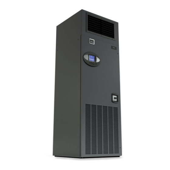
Sign In
Upload
Manuals
Brands
Emerson Manuals
Air Conditioner
Liebert Challenger 3000
Emerson Liebert Challenger 3000 Manuals
Manuals and User Guides for Emerson Liebert Challenger 3000. We have
5
Emerson Liebert Challenger 3000 manuals available for free PDF download: User Manual, Installation Manual, Operation & Maintenance Manual
Emerson Liebert Challenger 3000 User Manual (100 pages)
Intelligent Communications & Monitoring for Liebert Challenger 3000, Liebert Challenger ITR and Liebert DS
Brand:
Emerson
| Category:
Control Unit
| Size: 3.18 MB
Table of Contents
Table of Contents
3
1 Introduction
7
Features
7
Figure 1 Liebert Icom Components
7
2 Liebert Icom Display Components and Functions
8
Figure 2 Liebert Icom Display Components
8
Table 1 Keyboard Icons and Functions
9
Figure 3 Status Menu, Large Display, Graphical View
10
Figure 4 Liebert Icom Default Screen Symbols
10
Navigating through the Liebert Icom Menus
11
Control Interface
11
Accessing Submenus
11
Figure 5 Menu Tree-Small Display, Stand-Alone or Networked
11
Entering a Password
12
Figure 6 Entering a Password
13
Figure 7 Menu Tree-Large Display, Stand-Alone
13
Viewing Multiple Units with a Networked Large Display
14
Figure 8 Menu Tree-Large Display, Networked
14
Figure 9 User Menu Icons
15
User Menu Icons
15
Figure 10 Service Menu Icons
16
Service Menu Icons
16
3 Operation
18
Single Unit Functions
18
Unit/Fan Control
18
Figure 11 Start-Stop Priority Switches
18
General Compressor Requirements
21
Compressor Timing-Short-Cycle Protection
22
Compressor Sequencing on Two-Compressor Units
22
Motorized Ball Valve in Digital Scroll Units
22
MBV Operation after Compressor Is Turned off
23
Service Offset-Changing System Pressure Settings
23
Temperature Control-Single Source Cooling (no Extra Cooling Coil)
24
Temperature Proportional Band
24
Figure 12 Temperature Proportional Band
24
Compressor Control
25
Figure 13 One Single-Step Compressor Without Unloaders
25
Figure 14 Two Single-Step Compressors Without Unloaders or One Compressor with an Unloader
25
Figure 15 Two Compressors with Unloaders (Four-Step)
26
Figure 16 Digital Scroll Capacity Modulation, 10-100% Variable
26
Figure 17 Single and Dual Digital Scroll Compressor Activation Points
27
Chilled Water Control
28
Figure 18 DIP Switch Locations on Liebert Icom Control Board
28
Temperature Control-Second Cooling Source
29
Differential Temperatures / Controls (Comparator Circuit)
29
Figure 19 Chilled Water Valve Control (Example: Cooling)
29
Figure 20 Second Cooling Source and Two-Step Compressorized Cooling
30
Temperature Control-Reheat
31
Three-Stage Electric, Hot Gas and Hot Water Reheat
31
SCR Reheat
31
Figure 21 Three-Stage Heating
31
Table 4 Reheat Configuration Types
31
Figure 22 Two Single-Step Compressors with SCR Reheat Set to Tight Mode
32
Humidity Control
33
Figure 23 Two Single-Step Compressors with SCR Reheat Set to Standard Mode
33
Figure 24 Humidity Proportional Band
33
Humidification
34
Table 5 Parameters for Infrared Humidifier Control
34
Dehumidification
35
Table 6 Dehumidification with Comp Settings
35
Control Types
36
Temperature and Humidity Control Types
36
Humidity Sensor Reading Control Types
37
Figure 25 Placing Temperature and Temperature/Humidity Sensors
38
Supply Control
39
Supply Air
39
Event Types and Properties
40
Table 7 Possible Event Settings-Some Events Not Available in All Units
41
High- and Low-Temperature and Humidity Events
42
User Inputs
42
Customer Inputs
42
Table 8 Customer Inputs
42
Liebert Icom-DO
43
Table 9 Alarm Mapping
43
Possible Event Notifications
44
Wellness-Next Maintenance Calculation
44
Table 10 Event Notifications-Large or Small Display
44
Calculation of Next Maintenance and Diagnostics
45
4 Teamwork
47
Teamwork Modes
47
Application of Teamwork Modes
47
No Teamwork
47
Teamwork Mode 1
47
Figure 26 Teamwork Mode 1 with Two Cooling Units
48
Teamwork Mode 2
49
Standby-Rotation
49
5 Installing a Liebert Icom Unit - to -Unit Network
50
Placement of Cooling Units
50
Balancing Operating and Standby Units
50
Figure 27 Standby Unit Layout Example-10 Precision Cooling Units in Room
50
U2U Hardware: Cables and Network Switch
51
Wiring for Unit-To-Unit Communications-U2U
52
Wiring a Liebert Icom U2U Network
52
Figure 28 Connecting Two Cooling Units, each with a Small Display Using a Crossover Ethernet Cable
52
Table 11 Sample Liebert Icom Network Configurations
52
Figure 29 U2U Network Setup Diagram
53
Figure 30 Wiring a Small Display for Stand-Alone Operation
54
Figure 31 Wiring a Small Display for U2U Network Operation
55
Figure 32 Wiring a Large Display for U2U Network Operation
56
Figure 33 Liebert Vnsa with Optional Remote Large Display
57
Table 12 Ports Available for Connecting Liebert Icom Control Devices
57
6 External Communications-Building Management Systems, Liebert Sitescan
58
7 User Menu Parameters
59
Figure 34 User Menu Icons
59
Figure 35 Setpoints Parameters Screen
59
Figure 36 Set Alarms Screen
60
Figure 37 Sensor Data Screen
62
Figure 38 Sensor Data Screen - Page 2 (Return Only)
63
Figure 39 Display Setup Parameters Screen
64
Figure 40 Total Run Hours Parameters Screen
65
Figure 41 Sleep Mode Parameters Screen
65
8 Service Menu Parameters
66
Figure 42 Service Menu Main Screen
66
Figure 43 Setpoints Parameters Screen
67
Figure 44 Setpoints Parameters Screen
68
Figure 45 Setpoints Parameters Screen
69
Figure 46 Setpoints Parameters Screen
70
Figure 47 Setpoints Parameters Screen
71
Figure 48 Setpoints Parameters Screen
72
Table 13 Unit Diary Parameters
72
Figure 49 Standby Settings / Lead-Lag Parameters Screen
73
Figure 50 Wellness Basic Settings Screen
74
Figure 51 Wellness Motor Settings Parameters Screen
75
Figure 52 Wellness Compressor 1 Settings Parameters Screen
75
Figure 53 Wellness Compressor 1 Settings Parameters
76
Figure 54 Wellness Electric Heater 1 Settings Parameters Screen
76
Figure 55 Wellness Electric Heater 2 Settings Parameters Screen
77
Figure 56 Wellness Electric Heater 3 Settings Parameters Screen
77
Figure 57 Wellness Humidifier Settings Parameters Screen
78
Figure 58 Diagnostics / Service Mode Parameters Screen
79
Figure 59 Diagnostics / Service Mode Parameters Screen
80
Figure 60 Diagnostics / Service Mode Parameters Screen
81
Figure 61 Diagnostics / Service Mode Parameters Screen
82
Figure 62 Diagnostics / Service Mode Parameters Screen
83
Figure 63 Diagnostics / Service Mode Parameters Screen
84
Figure 64 Diagnostics / Service Mode Parameters Screen
84
Figure 65 Set Alarms Parameters Screen
85
Figure 66 Set Alarms Parameters Screen
86
Figure 67 Set Alarms Parameters Screen
86
Figure 68 Set Alarms Parameters Screen
87
Figure 69 Set Alarms Parameters Screen
87
Figure 70 Set Alarms Parameters Screen
88
Figure 71 Set Alarms Parameters Screen
88
Figure 72 Icom-DO Overview and Override
89
Figure 73 Icom-DO Events Setup - Page 2
89
Figure 73 Icom-DO Events Setup
90
Figure 74 Icom-DO Events Setup
90
Figure 75 Sensor Calibration / Setup Parameters
90
Figure 76 Sensor Calibration / Setup Parameters
91
Figure 77 Sensor Calibration / Setup Parameters
92
Figure 78 System / Network Setup Parameters-Large Display Only System
92
Figure 79 System / Network Setup Parameters-Large Display Only System
93
Figure 80 System/Network Setup Parameters Unit
94
Figure 81 System/Network Setup Parametersunit
95
Figure 82 Options Setup Parameters
96
Figure 83 Options Setup Parameters
97
Figure 84 Options Setup Parameters
98
Table 14 Service Contact Info Parameters
99
Advertisement
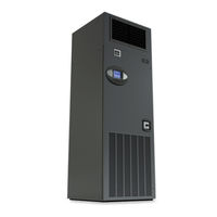
Emerson Liebert Challenger 3000 Installation Manual (88 pages)
environmental control systems
Brand:
Emerson
| Category:
Freezer
| Size: 2.53 MB
Table of Contents
Table of Contents
3
Important Safety Instructions
7
Save These Instructions
7
1 Introduction
9
System Descriptions
9
Self-Contained Systems
9
Chilled Water Models
9
Split Systems
10
2 Installation (Applicable to All Models )
11
Room Preparation
11
Equipment Inspection
11
Location Considerations
11
Equipment Handling
11
Handling with Skid
12
Removal of Skid
12
Figure 1 Removing Challenger from Skid
12
Table 1 Unit Net Weight
12
Figure 2 Upflow (BU) Cabinet Dimensions
13
Figure 3 Downflow (BF) Cabinet Dimensions
14
Piping Considerations
15
Drain Line
15
Table 2 Piping Connection Size
15
Figure 4 Piping Connections for Air-Cooled Units - Downflow Models
16
Figure 5 Piping Connections for Air-Cooled Units - Upflow Models
17
Figure 6 Piping Connections for Split System Fan Coil Units - Downflow Models
18
Figure 7 Piping Connections for Split System Fan Coil Units - Upflow Models
19
Figure 8 Piping Connections for Water/Glycol and GLYCOOL Units - Downflow Models
20
Figure 9 Piping Connections for Water/Glycol and GLYCOOL Units - Upflow Models
21
Figure 10 Piping Connections for Chilled Water Self-Contained Units - Downflow Models
22
Figure 11 Piping Connections for Chilled Water Self-Contained Units - Upflow Models
23
Humidifier Supply Water-Optional Infrared
24
Facility Fluid and Piping Maintenance
24
Electrical Connections
24
Figure 12 Electrical Connections
25
Figure 13 Electrical Field Connections for Liebert Icom
26
Balancing the Air Distribution
27
Under-Floor Discharge Systems
27
Ducted Applications
27
Plenum Installation
27
Table 3 Recommended Free Area Ft 2 (M 2 ) for Grilles or Perforated Panels at Output Velocities of 550
27
Checklist for Completed Installation
28
3 Air -Cooled Models -Self -Contained Compressor
29
Condenser Location
29
Electrical Connections
29
Line Voltage
29
Low Voltage
29
Liebert Lee-Temp/Flood Back Head Pressure Control Condensers
29
Figure 14 Air-Cooled Condensers
30
Table 4 Air-Cooled Condenser Statistics
30
Refrigerant Piping
31
Table 5 Recommended Line Sizes - OD Copper (Inches)
31
Fan Speed Control Systems
32
Table 6 Equivalent Lengths (Feet) for Various Pipe Fittings
32
Table 7 Indoor Unit Refrigerant Charge Lb (Kg)
32
Table 8 Line Charges - Refrigerant Per 100 Ft. (30 M) of Type "L" Copper Tube
32
Table 9 Condenser Refrigerant (Per Serial Tag)
32
Table 10 Fan Speed Suction Pressure Transducer Settings
34
Figure 15 General Arrangement-Air-Cooled Models with Fan Speed Control
35
Figure 16 General Arrangement-Air-Cooled Models with Digital Scroll and Fan Speed Control
36
Air-Cooled Condenser with Liebert Lee-Temp "Flooded Condenser" Head Pressure
37
Control System
37
Table 11 Lee-Temp Suction Pressure Transducer Settings
38
Figure 17 General Arrangement-Air-Cooled Models with Liebert Lee-Temp
39
Figure 18 General Arrangement-Air-Cooled Models with Digital Scroll and Lee-Temp
40
4 Water -Cooled Models -Self -Contained Compressor
41
Piping Considerations
41
Condenser
41
Figure 19 General Arrangement-Water-Cooled Models with Scroll Compressor
42
Figure 20 General Arrangement Diagram-Water-Cooled Models with Digital Scroll
43
Water Regulating Valve
44
Standard Valve - 150Psig (1034Kpa) System for 3 & 5-Ton Units (Johnson Controls Valve) High Pressure Valve - 350Psig (2413Kpa) System for 5-Ton Units
44
Controls Valve)
44
High Pressure Valve - 350 Psig (2413 Kpa) System for 3-Ton Units (Metrex Valve)
44
Figure 21 Johnson Controls Valve Adjustment
44
Motorized Ball Valve-Digital Scroll Compressors
45
Control
45
Figure 22 Metrex Valve Adjustment
45
Table 12 Refrigerant Control Settings Psi (Kpa)
45
Adjustment
46
Startup
46
Location
46
Manual Control
46
5 Glycol /Glycool-Cooled Models -Self -Contained Compressor
47
Drycooler Location
47
Drycooler Installation
47
Electrical Connections
47
Line Voltage
47
Low Voltage
47
Pump and Drycooler
47
Glycol Piping
48
Table 13 Room Dew Point Temperatures
49
Expansion Tanks, Fluid Relief Valves and Other Devices
50
Filling Instructions
50
Preparing the System for Filling
50
Table 14 Indoor Unit Glycol Volume Approximate Gallons (Liters) Max
50
Table 15 Volume in Standard Type "L" Copper Piping
50
Glycol Solutions
51
Filling the System
52
Table 16 Ethylene Glycol Concentrations
52
Figure 23 Drycoolers and Pump Packages
53
Figure 24 Pump Packages-Expansion Tank
54
Table 17 Mounting Hole Dimensional Data
54
Table 18 Drycooler Data
54
Table 19 Glycol Pump Data
54
Figure 25 General Arrangement-Glycol-Cooled Models with Scroll Compressor
55
Figure 26 General Arrangement-Glycol-Cooled Models with Digital Scroll
56
Figure 27 General Arrangement-GLYCOOL Models with Scroll Compressor
57
Figure 28 General Arrangement-GLYCOOL Models with Digital Scroll Compressor
58
Motor Ball Valve-Digital Scroll Compressors
59
Condenser
59
Glycol Regulating Valve
59
Standard Valve - 150Psig (1034Kpa) System for 3 & 5-Ton Units (Johnson Controls Valve) High Pressure Valve - 350Psig (2413Kpa) System for 5-Ton Units
59
Controls Valve)
59
High Pressure Valve - 350 Psig (2413 Kpa) System for 3-Ton Units (Metrex Valve)
59
Testing Valve Function
59
Table 20 Refrigerant Control Settings Psi (Kpa)
59
6 Chilled Water Models
60
Piping Considerations
60
Figure 29 Chilled Water General Arrangement - Upflow (BU)
60
Figure 30 Chilled Water General Arrangement - Downflow (BF) Models
61
7 Split System Models
62
Location Considerations
62
Air-Cooled Condensing Units
62
Water/Glycol-Cooled Condensing Units
62
Electrical Connections
62
Line Voltage
62
Low Voltage
63
Piping Considerations
63
Refrigerant Loop
63
Table 21 Unit Refrigerant Charge
64
Table 22 Line Charges - Refrigerant Per 100 Ft. (30 M) of Type "L" Copper Tube
64
Table 23 Recommended Refrigerant Lines (R407C) Sizes OD Copper
64
Quick Connect Fittings
65
Figure 31 Refrigerant Piping Diagram
65
Table 24 Line Coupling Sizes
65
Table 25 Equivalent Lengths (Feet) for Various Pipe Fittings
65
Outdoor Air-Cooled Condensing Units
66
Figure 32 Outdoor Air-Cooled Condensing Unit-Horizontal Air Discharge Models
66
Table 26 Horizontal Air Discharge Cabinet and Floor Planning Dimensional Data
67
Table 27 Horizontal Air Discharge Piping and Electrical Connection Data
67
Figure 33 Outdoor Air-Cooled Condensing Unit-Top Air Discharge Models
68
Table 28 Cabinet and Floor Planning Dimensional Data - Prop Fan Condensing Modules, Top Air
69
Table 29 Piping and Electrical Connections - Top Air Discharge
69
Figure 34 Electrical Field Connections, Prop Fan Condensing Module
70
Centrifugal Air-Cooled Condensing Units
71
Installing the Indoor Condensing Unit
71
Table 30 Indoor Centrifugal Condensing Unit
71
Ducting
72
Figure 35 Detail of Ceiling Hanging Bracket
72
Table 31 Airflow CFM (CMH)
72
Figure 36 3-Ton Centrifugal Air-Cooled Condensing Unit Dimensional Data & Piping Connections
73
Figure 37 3-Ton Centrifugal Air-Cooled Condensing Unit (Con't.)
74
Figure 38 5-Ton Centrifugal Air-Cooled Condensing Unit Dimensional Data
75
Figure 39 5-Ton Centrifugal Air-Cooled Condensing Unit Dimensional Data (Con't.)
76
Figure 40 Split Systems General Arrangement
77
Water and Glycol-Cooled Condensing Units
78
Piping Considerations
78
Condenser Water Requirements
78
Regulating Valve
78
Table 32 Water and Glycol-Cooled Condensing Unit Data
78
Glycol Systems
79
Figure 41 3-Ton Water/Glycol-Cooled Condensing Unit
79
Figure 42 3-Ton Water/Glycol-Cooled Condensing Unit (Con't.)
80
Figure 43 5-Ton Water/Glycol-Cooled Condensing Unit Dimensional Data
81
Figure 44 5-Ton Water/Glycol-Cooled Condensing Unit (Con't.)
82
8 R407C Refrigerant
83
Table 33 R407C Pressure/Temperature Chart for Operation and Superheat
83
Calculating Subcooling
84
Table 34 R407C Pressure/Temperature Chart for Subcooling Only (Liquid Measurements)
84
Emerson Liebert Challenger 3000 Installation Manual (76 pages)
Precision Cooling For Business-Critical Continuity, 3 & 5 Tons, 50 & 60Hz
Brand:
Emerson
| Category:
Control Systems
| Size: 1.77 MB
Table of Contents
Table of Contents
3
1 Introduction
7
System Descriptions
7
Self Contained Systems
7
Chilled Water Models
7
Split Systems
7
2 Installation
8
Room Preparation
8
Equipment Inspection
8
Location Considerations
8
Equipment Handling
8
Handling with Skid
8
Removal of Skid
9
Figure 1 Removing Challenger from Skid
9
Table 1 Unit Net Weight
9
Figure 2 Upflow (BU) Cabinet Dimensions
10
Figure 3 Downflow (BF) Cabinet Dimensions
11
Piping Considerations
12
Drain Line
12
Table 2 Piping Connection Size
12
Figure 4 Piping Connections for Air Cooled Units
13
Figure 5 Piping Connections for Split System Fan Coil Units
14
Figure 6 Piping Connections for Water/Glycol and GLYCOOL Units
15
Figure 7 Piping Connections for Chilled Water Self-Contained Units
16
Electrical Connections
18
Figure 8 Electrical Connections
18
Balancing the Air Distribution
19
Under-Floor Discharge Systems
19
And 600 Fpm (2.8 and 3.1 M/S)
19
Ducted Applications
20
Plenum Installation
20
Checklist for Completed Installation
20
3 Air Cooled Models
22
Condenser Location
22
Electrical Connections
22
Line Voltage
22
Low Voltage
22
Lee-Temp/Flood Back Head Pressure Control Condensers
22
Figure 9 Air Cooled Condensers
23
Table 4 Air Cooled Condenser Statistics
23
Refrigerant Piping
24
Table 5 Recommended Line Sizes - OD Copper (Inches)
24
Fan Speed Control Systems
25
Materials Supplied
25
Table 6 Equivalent Lengths (Feet) for Various Pipe Fittings
25
Table 7 Indoor Unit Refrigerant Charge Lbs (Kg) R22 or R407C (Per Unit Serial Tag)
25
Table 8 Line Charges - Refrigerant Per 100 Ft (30 M) of Type "L" Copper Tube
25
Table 9 Condenser Refrigerant (Per Serial Tag)
25
Dehydration/Leak Test and Charging Procedures for R22 (Standard) or R407C (Optional)
26
Figure 10 Air Cooled Fan Speed Control General Arrangement
27
Charging
28
Lee-Temp/Flood Back Head Pressure Control Systems
28
Piping
28
Table 10 Refrigerant Control Settings Psi (Kpa)
28
Materials Supplied
29
Dehydration/Leak Test and Charging Procedures for R22 (Standard) or R407C (Optional)
29
Charging
30
Table 11 Refrigerant Control Settings Psi (Kpa)
30
Figure 11 Air Cooled, Lee-Temp General Arrangement
31
4 Water Cooled Models
32
Piping Considerations
32
Condenser
32
Figure 12 Water Cooled General Arrangement
33
Water Regulating Valve
34
Standard Valve - 150Psig (1034Kpa) System for 3 & 5 Ton Units (Johnson Controls Valve)
34
High Pressure Valve - 350Psig (2413Kpa) System for 5 Ton Units (Johnson Controls Valve)28
34
Figure 13 Johnson Controls Valve Adjustment
34
High Pressure Valve - 350 Psig (2413 Kpa) System for 3 Ton Units (Metrex Valve)
35
Testing Valve Function
35
Figure 14 Metrex Valve Adjustment
35
Table 12 Refrigerant Control Settings Psi (Kpa)
35
5 Glycol /Glycool Cooled Models
36
Drycooler Location
36
Drycooler Installation
36
Electrical Connections
36
Line Voltage
36
Low Voltage
36
Pump and Drycooler
36
Glycol Piping
37
Table 13 Room Dew Point Temperatures
37
Expansion Tanks, Fluid Relief Valves and Other Devices
38
Filling Instructions
38
Preparing the System for Filling
38
Table 14 Indoor Unit Glycol Volume Approximate Gallons (Liters) Max
38
Table 15 Volume in Standard Type "L" Copper Piping
38
Glycol Solutions
39
Table 16 Ethylene Glycol Concentrations
39
Filling the System
40
Figure 15 Drycoolers and Pump Packages
41
Figure 16 Pump Packages-Expansion Tank
42
Table 17 Mounting Hole Dimensional Data
42
Table 18 Drycooler Data
42
Table 19 Glycol Pump Data
42
Figure 17 Glycol General Arrangement
43
Figure 18 GLYCOOL General Arrangement
44
Condenser
45
Glycol Regulating Valve
45
Standard Valve - 150Psig (1034Kpa) System for 3 & 5 Ton Units (Johnson Controls Valve)
45
High Pressure Valve - 350 Psig (2413 Kpa) System for 3 Ton Units (Metrex Valve)
45
Testing Valve Function
45
Table 20 Refrigerant Control Settings Psi (Kpa)
45
6 Chilled Water Models
46
Piping Considerations
46
Figure 19 Chilled Water General Arrangement - Upflow (BU)
46
Figure 20 Chilled Water General Arrangement - Downflow (BF) Models
47
7 Split System Models
48
Location Considerations
48
Air Cooled Condensing Units
48
Water/Glycol Cooled Condensing Units
48
Electrical Connections
48
Line Voltage
48
Low Voltage
48
Piping Considerations
49
Refrigerant Loop
49
Table 21 Unit Refrigerant Charge
50
Table 22 Line Charges - Refrigerant Per 100 Ft (30 M) of Type "L" Copper Tube
50
Table 23 Recommended Refrigerant Lines (R22 or R407C) Sizes OD Copper
50
Table 24 Line Coupling Sizes
50
Figure 21 Refrigerant Piping Diagram
51
Table 25 Equivalent Lengths (Feet) for Various Pipe Fittings
51
Quick Connect Fittings
52
Outdoor Air Cooled Condensing Units
53
Figure 22 Outdoor Air Cooled Condensing Unit-Horizontal Air Discharge Models
53
Table 26 Horizontal Air Discharge Cabinet and Floor Planning Dimensional Data
54
Table 27 Horizontal Air Discharge Piping and Electrical Connection Data
54
Figure 23 Outdoor Air Cooled Condensing Unit-Top Air Discharge Models
55
Discharge
56
Table 28 Cabinet and Floor Planning Dimensional Data - Prop Fan Condensing Modules, Top Air
56
Table 29 Piping and Electrical Connections - Top Air Discharge
56
Figure 24 Electrical Field Connections, Prop Fan Condensing Module
57
Centrifugal Air Cooled Condensing Units
58
Installing the Indoor Condensing Unit
58
Table 30 Indoor Centrifugal Condensing Unit
58
Figure 25 Detail of Ceiling Hanging Bracket
59
Ducting
60
Table 31 Airflow CFM (CMH)
60
Figure 26 2 and 3 Ton Centrifugal Air Cooled Condensing Unit Dimensional Data & Piping Connections
61
Figure 27 3 Ton Centrifugal Air Cooled Condensing Unit (Con't.)
62
Figure 28 5 Ton Centrifugal Air Cooled Condensing Unit Dimensional Data
63
Figure 29 5 Ton Centrifugal Air Cooled Condensing Unit Dimensional Data (Con't.)
64
Figure 30 Split Systems General Arrangement
65
Water and Glycol Cooled Condensing Units
66
Piping Considerations
66
Condenser Water Requirements
66
Regulating Valve
66
Glycol Systems
66
Table 32 Water and Glycol Cooled Condensing Unit Data
66
Figure 31 2 and 3 Ton Water/Glycol Cooled Condensing Unit
67
Figure 32 3 Ton Water/Glycol Cooled Condensing Unit (Con't.)
68
Figure 33 5 Ton Water/Glycol Cooled Condensing Unit Dimensional Data
69
Figure 34 5 Ton Water/Glycol Cooled Condensing Unit (Con't.)
70
8 R407C Refrigerant
71
Suction Gas)
71
Calculating Subcooling
72
Table 34 R407C Pressure/Temperature Chart for Subcooling Only (Liquid Measurements)
72
Advertisement
Emerson Liebert Challenger 3000 Operation & Maintenance Manual (72 pages)
Precision Cooling For Business-Critical Continuity
Brand:
Emerson
| Category:
Air Conditioner
| Size: 3.69 MB
Table of Contents
Table of Contents
3
Important Safety Instructions Save These Instructions
7
1 Introduction
9
System Descriptions
9
Compressorized Systems
9
GLYCOOL ™ (Chilled Glycol Cooling) Systems
9
Chilled Water Systems
9
2 Startup
10
Startup Procedure
10
3 Operation with Icom Control
12
Features
12
Figure 1 Liebert Icom Components
12
4 Liebert Icom Display Components and Functions
13
Table 1 Keyboard Icons and Functions
14
Navigating through the Liebert Icom Display
15
Figure 3 Liebert Icom Default Screen Symbols
15
Figure 4 Liebert Icom Default Home Screen—Graphical View
15
Control Interface-Three Main Menus
16
Figure 5 Liebert Icom Default Home Screen—Simple View
16
Accessing Menus and Settings
17
Entering the Password
17
Accessing Submenus
18
Figure 7 Menu Tree—Large and Small Displays, Stand-Alone or Networked
19
Changing Operational Settings
20
Figure 8 Liebert Icom User Menu Icons
20
Changing Liebert Icom's Display Settings
21
Figure 9 Display Setup Screen
21
Graphical Data Record
22
Liebert Icom Service Menu Icons and Legend
22
Figure 10 Temperature Graph
22
Figure 11 Liebert Icom Service Menu Icons
22
Wiring for Unit-To-Unit Communications-U2U
23
Liebert Icom U2U Ethernet Network
23
Wiring a Liebert Icom U2U Network
23
Table 2 Sample Liebert Icom Network Configurations
23
Figure 12 U2U Network Setup Diagram
25
Figure 13 Liebert Icom Wiring—Unit as Shipped
27
Figure 14 Wiring a Small Display for U2U Network Operation
28
Figure 15 Wiring a Large Display for U2U Network Operation
29
Figure 16 Liebert Icom Input-Output Control Board
30
Entering Network Setup Information
31
Figure 17 Control Board U2U Network Setup Screen
31
Figure 18 Liebert Icom Display U2U Network Setup Screen
31
Viewing Multiple Units with a Networked Large Display
32
Figure 19 Menu Tree—Large Display, Networked
32
5 Operation
33
Single Unit Functions
33
Unit/Fan Control
33
Figure 20 Start-Stop Priority Switches
33
General Compressor Requirements
34
Compressor Timing
35
Control Types
36
Proportional Control
36
PI Control
36
Intelligent Control (Chilled Water Only)
37
6 Alarm Descriptions
38
Standard Alarms
38
Change Filter
38
Compressor Overload
38
High Head Pressure
39
High Humidity
39
High Humidity and Low Humidity (Simultaneously)
39
High Temperature
39
High Temperature and Low Temperature (Simultaneously)
39
Humidifier Problem
39
Loss of Air Flow
40
6.1.10 Loss of Power
40
6.1.11 Low Humidity
40
6.1.12 Low Suction Pressure
40
6.1.13 Low Temperature
40
6.1.14 Main Fan Overload
40
6.1.15 Short Cycle
40
Optional Alarms
41
Loss of Water Flow
41
Smoke Detected
41
Standby GC Pump on
41
Standby Unit on
41
Water under Floor
41
Set Alarms-User Menus
41
Table 3 Set Alarms-User Menus
41
7 Component Operation and Maintenance
42
System Testing
42
Environmental Control Functions
42
Figure 21 Liebert Leak Detection Units
43
Figure 22 Recommended Liquid Sensor Locations
44
Table 4 Zone Leak Detection Kit Installation Scenarios
44
Filters
45
Blower Package
45
Fan Impellers and Bearings
45
Belt
45
Air Distribution
46
Refrigeration System
46
Suction Pressure
46
Table 5 Recommended Free Area Ft 2 (M 2 ) for Grilles or Perforated Panels at Output Velocities
46
Of 550 and 600 Fpm (2.8 and 3.1 M/S)
46
Table 6 Suction Pressures - R407C
46
Discharge Pressure
47
Superheat
47
Thermostatic Expansion Valve
47
Table 7 Discharge Pressures
47
Hot Gas Bypass Valve-Not Available on Digital Scroll Units
48
Air Cooled Condenser
48
Water/Glycol Cooled Condensers
49
Figure 23 Outdoor Fan/Condenser Configuration
49
Motorized Ball Valve-Digital Scroll Compressor
50
Regulating Valve-Scroll Compressor
50
Figure 24 Johnson Controls Valve Adjustment
51
Figure 25 Metrex Valve Adjustment
51
7.4.10 Drycooler Settings
52
Table 8 Water/Glycol System Conditions Requiring Optional Settings for Aquastats
52
Table 9 Aquastat Settings-Two-Fan through Four-Fan Drycoolers
52
7.4.11 Compressor Oil
53
Compressor Replacement
53
Compressor Functional Check
53
Table 10 Compressor Oil Types
53
Standard Scroll Compressor Replacement
54
Digital Scroll Compressor Replacement Procedure
55
Facility Fluid and Piping Maintenance for Water and Glycol Systems
55
Infrared Humidifier
56
Figure 26 Infrared Humidifier Lamps
57
Steam Generating Humidifier
58
Figure 27 Steam Generating Humidifier
58
Table 11 Humidifier Canister Part Numbers
60
Table 12 Blower Troubleshooting
62
Table 13 Chilled Water Troubleshooting
62
Table 14 Compressor and Refrigeration System Troubleshooting
63
Table 15 Dehumidification Troubleshooting
65
Table 16 Glycol Pump Troubleshooting
65
Table 17 Infrared Humidifier Troubleshooting
65
Table 18 Steam Generating Humidifier Troubleshooting
66
Table 19 Reheat Troubleshooting
67
M Onthly M Aintenance I Nspection C Hecklist
68
S Emiannual M Aintenance I Nspection C Hecklist
69
Emerson Liebert Challenger 3000 User Manual (32 pages)
Brand:
Emerson
| Category:
Power Supply
| Size: 1.65 MB
Table of Contents
Table of Contents
3
Important Safety Instructions
5
Save These Instructions
5
Glossary of Symbols
7
1 Introduction
8
Figure 1 Front View of UPS
8
Figure 2 1000 and 1500-Rear View
8
Figure 3 2200-Rear View
9
Figure 4 3000-Rear View
9
2 What S Included
10
Accessories
10
What' Included
10
Figure 5 Accessories
10
3 Installation
11
Preparation
11
Figure 6 Placing the Liebert PSI XR
11
Tower UPS Installation
12
Figure 7 Tower Configuration-Attach Tower Stands
12
Rack-Mount UPS Conversion and Installation
13
Figure 8 Convert the Liebert PSI XR for Rack Installation
13
Orient Display for Installation
14
Charge Batteries and Perform Battery Startup
14
Connect Input Power and Load
14
Figure 9 Orienting the UPS Display
14
Figure 10 Connect Input Power and Load
14
Connect Network Surge Protection
15
Connect Communication Interface
15
Figure 11 Connect Network Surge Protection
15
Figure 12 Connect Communication Interface
15
Set up Liebert Multilink Software
16
EPO Switch
16
Figure 13 EPO Connection for Normally Open Operation
16
External Battery Cabinet Installation
17
Figure 14 Install the External Battery Cabinet in Tower Installation
17
Table 1 Battery Cabinet Connector Color Key
17
Figure 15 Connect Battery Cabinets to UPS
18
4 Controls and Indicators
19
Figure 16 Display and Status Indicators
19
Table 2 Display and Status Indicators Function, Legend
19
Control Buttons
20
On/Alarm Silence/Manual Self-Diagnostic Test
20
Off Button
20
Status Indicators
20
Status Change Button
20
Load Level Indicator
20
Battery Level Indicator
21
UPS Status Indicators
21
Table 3 Status Indicators-Color, Illumination Mode
21
Table 3
21
5 Operational Modes
22
Normal Mode
22
Buck/Boost Mode
22
Battery Mode
22
Battery Recharge Operation
22
6 Communication
23
DB-9 Connector
23
Remote Shutdown Via the DB-9 Connector
23
Any Mode Shutdown Via Pins 5 & 6
23
Battery Mode Shutdown Via Pins 4 & 5
23
Network Surge Protection Connectors
23
Pin Assignment
23
Table 4 DB-9 Pin Assignment
23
UPS Communications
24
UPS Inverter/Transfer Voltage Configurations
24
Figure 17 DIP Switch Settings for 120V System
24
Voltage Configurations
24
Table 5 Voltage Configurations
24
7 Battery Maintenance
25
Battery Charging, Storage
25
Internal Battery Replacement Procedure
25
Figure 18 Battery Replacement
25
8 Pecifications
26
Liebert PSI XR Specifications
26
Table 6 Liebert PSI XR Specifications
26
Battery Cabinet Specifications
27
Table 7
27
Table 8 Liebert PSI XR Battery Run Times
28
9 Troubleshooting
30
Table 9 Troubleshooting-Problems, Causes and Solutions
30
Advertisement
Related Products
Emerson Vanessa 30000 Series
Emerson Rosemount 300S WirelessHART
Emerson Rosemount 300SMV WirelessHART
Emerson Rosemount 3051SF Series
Emerson Rosemount 3051 CF Series
Emerson Rosemount MultiVariable 3051SFA
Emerson Rosemount 3051L
Emerson Copeland Scroll ZH 30 K4E
Emerson Rosemount 3051SHP
Emerson Rosemount 306
Emerson Categories
Controller
Control Unit
Transmitter
Measuring Instruments
Fan
More Emerson Manuals
Login
Sign In
OR
Sign in with Facebook
Sign in with Google
Upload manual
Upload from disk
Upload from URL