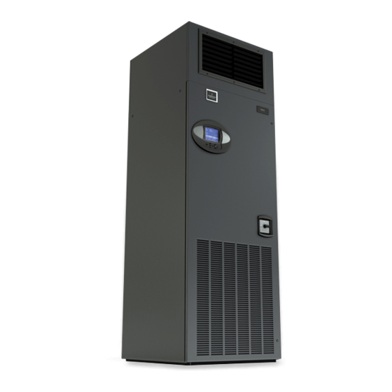
Emerson Liebert Challenger 3000 User Manual

Emerson Liebert Challenger 3000 User Manual

Intelligent communications & monitoring for liebert challenger 3000, liebert challenger itr and liebert ds
Hide thumbs Also See for Liebert Challenger 3000:
Table of Contents

Advertisement

Liebert
iCOM
®
®
User Manual - Intelligent Communications & Monitoring for Liebert Challenger 3000
Challenger ITR
and Liebert DS
Precision Cooling
For Business-Critical Continuity™
, Liebert

Advertisement

Table of Contents
loading

Summary of Contents for Emerson Liebert Challenger 3000

  • Page 1 Precision Cooling For Business-Critical Continuity™ Liebert iCOM ® ® User Manual - Intelligent Communications & Monitoring for Liebert Challenger 3000 ™ , Liebert Challenger ITR ™ and Liebert DS ™...
  • Page 3: Table Of Contents

    TABLE OF CONTENTS ............1 NTRODUCTION Features .
  • Page 4 Wellness—Next Maintenance Calculation ........38 3.9.1 Calculation of Next Maintenance and Diagnostics.
  • Page 5 Figure 21 Three-stage heating ............. 25 Figure 22 Two single-step compressors with SCR reheat set to Tight mode .
  • Page 6 Figure 71 Set alarms parameters screen - Page 7 ..........82 Figure 72 iCOM-DO Overview and Override - Page 1.
  • Page 7: Introduction

    Introduction NTRODUCTION ® The Liebert iCOM control offers the highest capabilities in unit control, communication and moni- toring of Liebert mission-critical cooling units. Liebert iCOM may be used to combine multiple cooling units into a team that operates as a single entity, enhancing the already-high performance and efficiency of Liebert’s units.
  • Page 8: Liebert Icom Display Components And Functions

    Liebert iCOM Display Components and Functions COM D IEBERT I ISPLAY OMPONENTS AND UNCTIONS The small and the large display have a common key layout, as shown in Figure 2. Figure 2 Liebert iCOM display components Liquid Crystal Display LED Status Indicators (top LED is red or flashing red;...
  • Page 9: Table 1 Keyboard Icons And Functions

    Liebert iCOM Display Components and Functions Table 1 Keyboard icons and functions Icon Key Name Function On/Off Key Controls the operational state of the cooling unit. Alarm Key Silences an alarm. Help Key Accesses integrated help menus. ESCape Key Returns to the previous display view. Enter Key Confirms all selections and selects icons or text.
  • Page 10: Figure 3 Status Menu, Large Display, Graphical View

    Liebert iCOM Display Components and Functions Figure 3 Status menu, large display, graphical view Humidity Humidity Supply Air Temperature Supply Air Setpoint Sensor Setpoint Setpoint System or Temperature Reading Unit # view (optional) UNIT 1 Temperature Sensor Percent Hot Water Reading 73.4°F 50.9°F...
  • Page 11: Navigating Through The Liebert Icom Menus

    Liebert iCOM Display Components and Functions Navigating Through the Liebert iCOM Menus Liebert iCOM shows icons and text for monitoring and controlling your Liebert cooling units or net- work of cooling units. The number of icons and amount of text shown depends on the display size. 2.1.1 Control Interface When the buttons on the Liebert iCOM control have not been pressed for a short period, the display...
  • Page 12: Entering A Password

    Liebert iCOM Display Components and Functions Accessing Submenus on Small Displays While viewing the menu you wish to access (User, Service or Advanced), use the up and down arrow keys to scroll through the icons page-by-page. To scroll through the icons one-by-one, press the enter key and then use the up and down arrow keys.
  • Page 13: Figure 6 Entering A Password

    Liebert iCOM Display Components and Functions Figure 6 Entering a password UNIT 01 SETPOINTS U101 PASSWORD (Actual Level 0) ???? U102 Temperature Setpoint 73°F U103 Humidity Setpoint 50.0% U104 Humidity Control Type Relative U105 Supply Sensor Control U106 Supply Setpoint 50°F U107 Backup Temperature Setpoint...
  • Page 14: Viewing Multiple Units With A Networked Large Display

    Liebert iCOM Display Components and Functions 2.1.4 Viewing Multiple Units with a Networked Large Display When you first wake up the control, press the Esc key to return to the System view Status menu. This view shows an average of all the units on the network and any alarms present. To view a specific unit on the network, press either the enter key or down arrow key.
  • Page 15: Figure 9 User Menu Icons

    Liebert iCOM Display Components and Functions Figure 9 User menu icons User Menu password: 1490 Table 2 User menu icons Icon Name Available On Display Description °C / °F View and change temperature and humidity % RH Setpoints Small & Large setpoints Displays the various part numbers of the Spare Part List...
  • Page 16: Figure 10 Service Menu Icons

    Liebert iCOM Display Components and Functions Table 2 User menu icons (continued) Icon Name Available On Display Description Allows setback settings for non-peak Sleep Mode Small & Large operation Contains key contact information for local Service Contact Info Small & Large service, including names and phone numbers Change settings for Liebert iCOM Discrete iCOM-DO...
  • Page 17 Liebert iCOM Display Components and Functions Table 3 Service menu icons (continued) Available On Icon Name Display Description Sensor Allows calibration of sensors Small & large + / - Calibration/Setup NETWORK System/Network Allows setup and U2U communication for multiple units Large Setup Options Setup...
  • Page 18: Operation

    Operation PERATION The Liebert iCOM display provides viewing, trending and configuration capability for Liebert cooling units. All unit settings and parameters can be viewed and adjusted through three menus: User, Ser- vice and Advanced. All active alarms are displayed on the LCD and annunciated. The control is shipped from the factory with default selections for all necessary settings.
  • Page 19 Operation Autorestart When there is a loss of power to the cooling unit and power comes back, the unit will return to its pre- vious operating status—on if it was on before the power off, off if it was off. When power returns, the autorestart time—time-selectable: Single Unit Auto Restart (Service Menu, Options Setup)—controls the start of the unit.
  • Page 20 Operation Chilled Water Units with Variable Fan Speed—EC or Variable Frequency Drives VSD Fan Speed parameter can be found in the Service Menu / Setpoints submenu on page 5 of 6. This menu allows the cooling unit's fan motor speed to be configured and adjusted for a variety of applica- tions.
  • Page 21: General Compressor Requirements

    Operation 3.1.2 General Compressor Requirements Low-Pressure Time Delay When the compressor starts, the low-pressure input is ignored for a selected period of time based on the setting of the Low Pressure Alarm Delay (Service Menu, Options Setup). This time is usually set to 3 minutes on air-cooled units, and to 0 or 1 minute on water cooled units.
  • Page 22: Compressor Timing-Short-Cycle Protection

    This delay may cause a short cycle if there is a very light room load. A short cycle means that the compressor has cycled On and Off 10 times in the past hour. Should this occur, contact your local Emerson representative to adjust the minimum compressor off delay. 3.1.4...
  • Page 23: Mbv Operation After Compressor Is Turned Off

    Operation When Auto BV Control is selected, the motorized ball valve functions as it would be during normal system operation. NOTE Compressor operation will be delayed 30 seconds to allow the motorized ball valve to position itself for initial startup. When Manual BV Control is selected, the user must be careful in setting the MBV position because the ball valves will remain in the position set in the Service menu until the control is switched back to Auto or until a technician changes the valves to another manual position (the motorized ball valve in...
  • Page 24: Temperature Control-Single Source Cooling (No Extra Cooling Coil)

    Operation Temperature Control—Single Source Cooling (No Extra Cooling Coil) 3.2.1 Temperature Proportional Band The control uses the temperature proportional band to determine which operation to perform (cool- ing/heating) and how much capacity to provide. The Temperature Proportional Band is a user-defined range that is divided into two equal parts for cooling and heating.
  • Page 25: Compressor Control

    Operation 3.2.2 Compressor Control Depending on its type, a Liebert Precision Cooling unit may have one or two compressors with or without unloaders or variable capacity. Compressor Proportional Bands One Single-Step Compressor Without Unloaders—One-Step One single-step compressor, Cool 1, is started at 100% call for cooling from the temperature propor- tional band and stopped at 0% (see Figure 13).
  • Page 26: Figure 15 Two Compressors With Unloaders (Four-Step)

    Operation Two Compressors With Unloaders—Four-Step The first two-step compressor is started unloaded at 33% calculated output from the temperature pro- portional band and stopped at 17%. At 80% Compressor 1 will be loaded, at 70% unloaded. The second compressor starts unloaded at 63% and stops at 47%. At 100%, Compressor 2 will be loaded, at 90% unloaded (see Figure 15).
  • Page 27: Figure 17 Single And Dual Digital Scroll Compressor Activation Points

    Operation On single and dual digital scroll compressor systems, the first compressor is started at 25% calculated output from the temperature proportional band and stopped at 10%. On dual digital scroll compressor systems, the second compressor is started at 35% and stopped at 20%, see Figure 17. When a com- pressor is started, the solenoid is energized longer than it is de-energized to match the call for cooling.
  • Page 28: Chilled Water Control

    Enabling the feedback signal will eliminate the need to drive the valve closed after a loss of power or Unit Off command, decreasing the unit’s restart time. Authorized Emerson personnel should use the following steps to enable the feedback signal: 1.
  • Page 29: Temperature Control-Second Cooling Source

    Operation Chilled water units that contain a motorized ball valve(s) are connected to the control by an analog output. The analog output is driven proportionally to the call for cooling as shown in Figure 19. Larger chill water units may contain two motorized ball valves in which both valves are controlled in parallel.
  • Page 30: Figure 20 Second Cooling Source And Two-Step Compressorized Cooling

    Operation Figure 20 Second cooling source and two-step compressorized cooling Temp Setpoint: 70°F Proportional Band: 8°F Deadband: 2°F Valve Valve 100% Cool 1 Cool 2 Closed Open + 100 % Cooling ½ Dead- band Comp Source ½ Proportional Band ½ Proportional Band + 200% Band1: 2 Source...
  • Page 31: Temperature Control-Reheat

    Operation Temperature Control—Reheat If the room air temperature becomes too cold, the control will call for heating. Heating mode is con- trolled by the Temperature Proportional Band, explained in 3.2.1 - Temperature Proportional Band. 3.4.1 Three-Stage Electric, Hot Gas and Hot Water Reheat The Reheat Proportional Band is divided into three equal parts, each representing one reheat stage.
  • Page 32: Figure 22 Two Single-Step Compressors With Scr Reheat Set To Tight Mode

    Operation capacity is provided at 0% calculated output from the Temperature Proportional Band. As the call for cooling increases from 0% to 100%, the reheat capacity is slowly reduced by pulsing the reheat. At 100% call for cooling, the reheat is deactivated and the second single-step compressor is started. As the call for cooling is reduced, the reheat capacity is slowly increased.
  • Page 33: Humidity Control

    Operation Figure 23 Two single-step compressors with SCR reheat set to Standard mode Temp Setpoint : 70°F Cool 2 Proportional Band : 8°F Cool 1 Deadband : 0°F 100 % -100% Cooling Heating Cool 1 Off Cool 2 SCR Off ½...
  • Page 34: Humidification

    Operation When the return air humidity reaches the end of the proportional band, either 100% or -100%, full dehumidification or full humidification capacity is provided. No operation is performed when a 0% call is calculated. The control varies the call for dehumidifying and humidifying in 1% increments as the return air humidity moves through the proportional band halves.
  • Page 35: Dehumidification

    Operation 3.5.2 Dehumidification The Dehumidification Enable parameter (Service Menu, Options Setup) allows for enabling/disabling the dehumidification function. A call for dehumidification is calculated in the same way as a cooling request. The components (valves, compressors) will follow this dehumidification request as soon as it is higher than the request for cooling.
  • Page 36: Control Types

    Operation Reheat During Dehumidification Hot gas reheat or hot water reheat will start as described in 3.4 - Temperature Control—Reheat, when the temperature decreases during the dehumidification process. The parameter Electric Reheat Operation defines how the heaters react in case the temperature decreases during the dehumidification process.
  • Page 37: Humidity Sensor Reading Control Types

    Operation is programmed into the control. These rules simulate the actions that a human operator would take if manually controlling the system. This control type is commonly selected on chilled water units. NOTE The actual air temperature sensor reading is always displayed on the Status menu. The value displayed for the return air humidity sensor reading depends on the Humidity Sensor Control Type (see 3.6.2 - Humidity Sensor Reading Control Types).
  • Page 38: Figure 25 Placing Temperature And Temperature/Humidity Sensors

    Operation Figure 25 Placing temperature and temperature/humidity sensors Return Internal Temperature and Humidity Sensor 5 to 15feet (1.5 to 4.5m) Temperature Sensor Supply Air Liebert Precision Cooling Unit...
  • Page 39: Supply Control

    The supply air sensor must be connected to P13 pins 1 & 2. Contact your local Emerson representative for pricing and installation. • Supply Control: When the supply sensor is set to Control, the unit will control the amount of cooling / heating being provided based on maintaining the discharge air temperature.
  • Page 40: Event Types And Properties

    Operation Event Types and Properties Liebert iCOM events are used to inform the user of cooling unit operational status. All events are recorded in the Event Log, which is in the User Menu. The user can change the type (alarm, warn, message) and time delay of some events and can also enable or disable some events.
  • Page 41: Table 7 Possible Event Settings-Some Events Not Available In All Units

    Operation Table 7 Possible event settings—some events not available in all units Internal Delay Default Delay / Selectable Type Event (Before Action Occurs) (Before Action Occurs) (default) MAIN FAN OVERLOAD 2 seconds 5 seconds / 0 – 9999 * LOSS OF AIRFLOW 3 seconds 3 seconds / 0 –...
  • Page 42: High- And Low-Temperature And Humidity Events

    Operation 3.8.1 High- and Low-Temperature and Humidity Events High- and low-temperature and humidity alarms can be set for both the internal and optional exter- nal sensors. If a sensor reading exceeds a preset threshold, a warning will appear. These warnings are ignored after unit startup for a minimum of 1 minute.
  • Page 43: Liebert Icom-Do

    Operation 3.8.3 Liebert iCOM-DO The Liebert iCOM-DO is an optional discrete output relay card that can be connected to the Liebert iCOM controls that will provide a dry alarm contact for monitoring systems. The Liebert iCOM-DO is a direct replacement of the Liebert ENV-DO card that was supported on previous Liebert control sys- tems.
  • Page 44: Possible Event Notifications

    Operation 3.8.4 Possible Event Notifications Table 10 lists examples of alarms and warnings that can be configured for a cooling unit. When any of these occur, they will appear on the Liebert iCOM Status menu and will be recorded in the Liebert iCOM Event log.
  • Page 45: Calculation Of Next Maintenance And Diagnostics

    Operation 3.9.1 Calculation of Next Maintenance and Diagnostics If the unit includes any of the following components, they are included in the calculation: • Fan(s) • Compressor 1 • Compressor 2 • Electric Heaters • Humidifier For each component, the next maintenance will be calculated from the following parameters: •...
  • Page 46 Operation Fans / Heaters / Humidifier Settings and Diagnostics • Number of starts and Working hours are counted separately since the last maintenance. Total working hours can be read in the standard working hours window (customer window). • Average Working Hours is the calculation, resulting from starts and working hours. •...
  • Page 47: Teamwork

    Teamwork EAMWORK Unit-2-Unit (U2U) communications via a private network will allow the following functions to be placed into operation when the requirement exists. The user must install the correct hardware (see 5.0 - Installing a Liebert iCOM Unit-to-Unit Network) and properly program the units for the selected functionality.
  • Page 48: Figure 26 Teamwork Mode 1 With Two Cooling Units

    Teamwork The number of available units is calculated like: • In non-standby configuration: all units with fan on • In typical standby function (no cascade): all units with fan on • In cascade mode: all units that could operate (no alarm, which forces the unit to switch off, unit not switched off, etc.) NOTE 1.
  • Page 49: Teamwork Mode 2

    Teamwork 4.1.4 Teamwork Mode 2 Teamwork Mode 2 is designed to prevent units within a group from working against each other or “fighting.” It is best applied in large rooms with unbalanced heat loads. In Teamwork Mode 2, all parameters are shared equal to Mode 1, and Unit #1 averages all of the available unit sensor readings on the network to define whether there is a cooling, heating, dehumidification or humidification request.
  • Page 50: Installing A Liebert Icom Unit - To -Unit Network

    Installing a Liebert iCOM Unit-to-Unit Network COM U NSTALLING A IEBERT I ETWORK Connecting multiple Liebert iCOM-controlled cooling units in an Ethernet Unit-to-Unit (U2U) net- work enables the units to work together to achieve efficient cooling and humidity control of the condi- tioned space.
  • Page 51: U2U Hardware: Cables And Network Switch

    Installing a Liebert iCOM Unit-to-Unit Network U2U Hardware: Cables and Network Switch Plan wiring runs for U2U communication when designing the layout of your conditioned space. In addition to general good wiring practices, take into account: • Ethernet CAT5 or greater cable is required for interconnecting the units. •...
  • Page 52: Wiring For Unit-To-Unit Communications-U2U

    Installing a Liebert iCOM Unit-to-Unit Network Wiring for Unit-to-Unit Communications—U2U Cooling units come from the factory-wired for stand-alone operation. Liebert iCOM U2U Ethernet Network The Liebert iCOM U2U network must be isolated from other network traffic. The network switch(es) that connect Liebert iCOM controls need to be dedicated to supporting only Liebert iCOM communi- cation.
  • Page 53: Figure 29 U2U Network Setup Diagram

    Installing a Liebert iCOM Unit-to-Unit Network Large Displays A network switch is required to enable Ethernet communication on one or more cooling units with large displays. Each cooling unit with a large display requires two straight-through Ethernet cables from a network switch. One cable connects to port P64 on the Liebert iCOM input/output board and the other straight-through cable connects to the female-female coupler provided with the unit.
  • Page 54: Figure 30 Wiring A Small Display For Stand-Alone Operation

    Installing a Liebert iCOM Unit-to-Unit Network Wall-Mount Large Display Only large displays can be used for remotely monitoring and controlling cooling units connected on the same network. Each wall-mount large display requires 120V input power; Liebert provides an AC adapter wall plug. A straight-through Ethernet cable must be connected between the network switch and the P64 port on the back of the display.
  • Page 55: Figure 31 Wiring A Small Display For U2U Network Operation

    Installing a Liebert iCOM Unit-to-Unit Network Figure 31 Wiring a small display for U2U network operation Cable Cable 'C' P64A Connection Located Near I/O Board Used Standard Small Graphics Display (Rear View) U2U Networking Switch (Field-Supplied) Liebert iCOM I/O Board Straight-Through To / From Other 194273...
  • Page 56: Figure 32 Wiring A Large Display For U2U Network Operation

    Installing a Liebert iCOM Unit-to-Unit Network Figure 32 Wiring a large display for U2U network operation Cable Red Crossover Ethernet Cable Crossover Coupler (See Note 6) Cable 'C' See Note 4 P64A Connection Located Near I/O Board Optional Large Graphics Display Used (Rear View) Customer Connection Point...
  • Page 57: Figure 33 Liebert Vnsa With Optional Remote Large Display

    Installing a Liebert iCOM Unit-to-Unit Network Table 12 Ports available for connecting Liebert iCOM control devices Liebert vNSA With Number of Ports Number of Ports Number of Ports Remote Used to Connect Used to Available to Large Total Number Remote Large Interconnect Connect Liebert iCOM Model...
  • Page 58: External Communications-Building Management Systems, Liebert Sitescan

    ® External Communications—Building Management Systems, Liebert SiteScan —B XTERNAL OMMUNICATIONS UILDING ANAGEMENT YSTEMS IEBERT ® Liebert iCOM is capable of communicating with external monitoring systems, such as Building Man- ® agement Systems (BMS), Network Monitoring Systems (NMS), Liebert's SiteScan Web system and others.
  • Page 59: User Menu Parameters

    User Menu Parameters ARAMETERS User menus report general cooling unit operations and status. The user menu password is 1490. The User menu parameter tables in this manual may differ from the display on your cooling unit. The Liebert iCOM functions with several Liebert Precision Cooling units, each with its own set of control commands.
  • Page 60: Figure 36 Set Alarms Screen

    User Menu Parameters Spare Part List Spare Parts—The spare parts lists contains a detailed description and part number that can be used to order parts for the unit. These part numbers are specific to each model and option installed on the unit.
  • Page 61 User Menu Parameters Low Temperature Sensor A—This parameter is visible when the sensor A alarm is enabled. When enabled the low temperature alarm allows a user to adjust the point at which the actual sensor A tem- perature activates a Low Temperature Alarm High Humidity Sensor A—This parameter is visible when the sensor A alarm is enabled.
  • Page 62: Figure 37 Sensor Data Screen

    User Menu Parameters Figure 37 Sensor data screen UNIT 01 SENSOR DATA (page 1 of 2) U301 Optional Sensor A 1 72°F U302 Optional Sensor A 2 49.5% U303 Optional Sensor B 1 °F U304 Optional Sensor B 2 °F U305 Optional Sensor C 1 °F...
  • Page 63: Figure 38 Sensor Data Screen - Page 2 (Return Only)

    User Menu Parameters Figure 38 Sensor data screen - Page 2 (return only) UNIT 01 SENSOR DATA (page 2 of 2) U313 Daily High Temperature 13:59:31 73°F U314 Daily Low Temperature 08:04:38 66°F U315 Daily High Humidity 08:16:11 48.5% U316 Daily Low Humidity 08:03:47 48.3%...
  • Page 64: Figure 39 Display Setup Parameters Screen

    User Menu Parameters Figure 39 Display setup parameters screen SYSTEM DISPLAY SETUP U401 Language ENGLISH U402 Date 7/3/2010 U403 Time 14:01:49 U404 Temperature Indication °F U405 Display Contrast U406 Buzzer Frequency Off/ 0 U407 Backlite Off after U408 Screen Graphical Comma U409 Display Shows ACT+SET...
  • Page 65: Figure 40 Total Run Hours Parameters Screen

    User Menu Parameters Figure 40 Total run hours parameters screen SYSTEM TOTAL RUN HOURS U501 Actual Hours Limit U502 Fan Motor (s) U503 Compressor 1 U504 Compressor 2 U505 Chilled Water/Free Cool U506 Hot Gas / HotWater U507 Electric Heater1 U508 Electric Heater 2 U509...
  • Page 66: Service Menu Parameters

    Service Menu Parameters ERVICE ARAMETERS Service menus allow customized settings for site operations. The password for service menu parame- ters is 5010. The Liebert iCOM control firmware is being updated constantly. As a result, the Service menu parameter tables shown in this manual may be slightly different than what is shown on your cooling unit's display.
  • Page 67: Figure 43 Setpoints Parameters Screen

    Service Menu Parameters Figure 43 Setpoints parameters screen - Page 1 UNIT 01 SETPOINTS (pg 1 of 6) S101 PASSWORD (Actual Level 0) ???? S102 Temperature Setpoint 73°F S103 Control Type Proportional S104 Temperature Proportional Band 5°F S105 Temperature Integration Time S106 S107 AutoSet Enable...
  • Page 68: Figure 44 Setpoints Parameters Screen

    Service Menu Parameters Figure 44 Setpoints parameters screen - Page 2 UNIT 01 SETPOINTS (pg 2 of 6) S112 PASSWORD (Actual Level 0) ???? S113 Humidity Setpoint S114 Humidity Control Type Relative S115 Humidity Proportional Band 10.0% S116 Humidity Integration Time 0min S117 Humidity DeadBand...
  • Page 69: Figure 45 Setpoints Parameters Screen

    Service Menu Parameters Figure 45 Setpoints parameters screen - Page 3 UNIT 01 SETPOINTS (pg 3 of 6) S123 PASSWORD (Actual Level 0) ???? S124 Supply Sensor Control S125 Supply Setpoint 50°F S126 Supply Control Type Proportional S127 Supply Proportional Band 12°F S128 Supply Integration...
  • Page 70: Figure 46 Setpoints Parameters Screen

    Service Menu Parameters Figure 46 Setpoints parameters screen - Page 4 UNIT 01 SETPOINTS (pg 4 of 6) S134 PASSWORD (Actual Level 0) ???? S135 DT between Room / Outdoor Type Disable S136 DT between Room Air / Outdoor °F S137 DT between Room / FC Type Disable...
  • Page 71: Figure 47 Setpoints Parameters Screen

    Service Menu Parameters Figure 47 Setpoints parameters screen - Page 5 UNIT 01 SETPOINTS (pg 5 of 6) S145 PASSWORD (Actual Level 0) ???? S146 VSD Fanspeed Delta S147 VSD Setpoint STD 100% S148 VSD Setpoint MIN S149 VSD Setpoint Dehum S150 VSD Setpoint No Power 100%...
  • Page 72: Figure 48 Setpoints Parameters Screen

    Service Menu Parameters Figure 48 Setpoints parameters screen - Page 6 UNIT 01 SETPOINTS (pg 6 of 6) S156 PASSWORD (Actual Level 0) ???? S157 SCR Control Type S158 Start Compressor 1 At S159 Stop Compressor 1 At S160 Compressor 1 Stop Delay S161 Start Compressor 2 At S162...
  • Page 73: Figure 49 Standby Settings / Lead-Lag Parameters Screen

    Service Menu Parameters Figure 49 Standby settings / lead-lag parameters screen STANDBY SETTINGS / LEAD-LAG SYSTEM S501 PASSWORD (Actual Level 0) ???? S502 Number of Standby Units S503 Rotation Frequency S504 Rotate at (hour) S505 Rotate at (minute) S506 Rotate by S507 Perform one Rotation S508...
  • Page 74: Figure 50 Wellness Basic Settings Screen

    Service Menu Parameters Figure 50 Wellness basic settings screen- Page 1 WELLNESS basic settings (page 1 of 8) SYSTEM S001 PASSWORD (Actual Level 0) ???? S002 Maintenance Frequency Per Year S003 Max Bonus S004 Max Penalty S005 Last Maintenance 08/17/2010 S006 Service Engineer NOBODY...
  • Page 75: Figure 51 Wellness Motor Settings Parameters Screen

    Service Menu Parameters Figure 51 Wellness motor settings parameters screen - Page 2 WELLNESS motor settings (page 2 of 8) UNIT 1 S012 PASSWORD (Actual Level 0) ???? S013 Number of Starts S014 Run Hours 22hrs S015 Average Run Time 188min S016 Starts per Day Best...
  • Page 76: Figure 53 Wellness Compressor 1 Settings Parameters

    Service Menu Parameters Figure 53 Wellness compressor 1 settings parameters - Page 4 WELLNESS compressor2 settings (page 4 of 8) UNIT 1 S034 PASSWORD (Actual Level 0) ???? S035 Number of Starts S036 Run Hours 7hrs S037 Average Run Time 140min S038 Starts per Day Best...
  • Page 77: Figure 55 Wellness Electric Heater 2 Settings Parameters Screen

    Service Menu Parameters Figure 55 Wellness electric heater 2 settings parameters screen - Page 6 WELLNESS el heater 2 settings (page 6 of 8) UNIT 1 S056 PASSWORD (Actual Level 0) ???? S057 Number of Starts S058 Run Hours 0hrs S059 Average Run Time 0min...
  • Page 78: Figure 57 Wellness Humidifier Settings Parameters Screen

    Service Menu Parameters Figure 57 Wellness humidifier settings parameters screen - Page 8 WELLNESS humidifier settings (page 8 of 8) UNIT 1 S078 PASSWORD (Actual Level 0) ???? S079 Number of Starts S080 Run Hours 0hrs S081 Average Run Time 0min S082 Starts per Day Best...
  • Page 79: Figure 58 Diagnostics / Service Mode Parameters Screen

    Service Menu Parameters Figure 58 Diagnostics / service mode parameters screen - Page 1 DIAGNOSTICS / SERVICE MODE (page 1 of 7) UNIT 01 S301 PASSWORD (Actual Level 0) ???? S302 HP 1 Alarm Code S303 HP 2 Alarm Code S304 HT 1 Alarm Counter S305...
  • Page 80: Figure 59 Diagnostics / Service Mode Parameters Screen

    Service Menu Parameters Figure 59 Diagnostics / service mode parameters screen - Page 2 DIAGNOSTICS / SERVICE MODE (page 2 of 7) UNIT 01 S312 PASSWORD (Actual Level 0) ???? S313 Manual Mode S314 Motors S315 Compressor 1 S316 Compressor 1 Capacity S317 Compressor 1 Cycle Ramp S318...
  • Page 81: Figure 60 Diagnostics / Service Mode Parameters Screen

    Service Menu Parameters Figure 60 Diagnostics / service mode parameters screen - Page 3 DIAGNOSTICS / SERVICE MODE (page 3 of 7) UNIT 01 S323 PASSWORD (Actual Level 0) ???? S324 Electric Heat 1 (or HG/HW) S325 Electric Heat 2 (or E .Heat 1) S326 Electric Heat 3 (or E .Heat 2) S327...
  • Page 82: Figure 61 Diagnostics / Service Mode Parameters Screen

    Service Menu Parameters Figure 61 Diagnostics / service mode parameters screen - Page 4 DIAGNOSTICS / SERVICE MODE (page 4 of 7) UNIT 01 S334 PASSWORD (Actual Level 0) ???? S335 Alarm Relay S336 K11 Relay S337 3P 1/2 Actuator Open On Off S338 3P 1/2 Actuator Close...
  • Page 83: Figure 62 Diagnostics / Service Mode Parameters Screen

    Service Menu Parameters Figure 62 Diagnostics / service mode parameters screen - Page 5 DIAGNOSTICS / SERVICE MODE (page 5 of 7) UNIT 01 S345 Status Remote Shutdown 0–0 S346 Status Airflow Loss S347 Status Motor Overload 0–0 S348 Status Filter S349 Status Customer Input 1 S350...
  • Page 84: Figure 63 Diagnostics / Service Mode Parameters Screen

    Service Menu Parameters Figure 63 Diagnostics / service mode parameters screen - Page 6 DIAGNOSTICS / SERVICE MODE (page 6 of 7) UNIT 01 S356 Status HP1 S357 Status LP1 0–0 S358 Status C1 OL 0–0 S359 Status HP2 S360 Status LP2 0–0 S361...
  • Page 85: Figure 65 Set Alarms Parameters Screen

    Service Menu Parameters Status DT3 (Room/Setpoint)—This indicates if the delta T between room return air temperature and unit air temperature setpoint has been met. Status Min CW—This indicates if the freecooling or chilled water temperature is below the mini- mum chilled water setpoint. LWD Value—(HPM only) On units with the optional analog Leakage Water Detector, this parameter will display percent leakage from 0-100%.
  • Page 86: Figure 66 Set Alarms Parameters Screen

    Service Menu Parameters Figure 66 Set alarms parameters screen - Page 2 SET ALARMS (page 2 of 7) UNIT 01 S212 PASSWORD (Actual Level 0) ???? S213 Customer Input 1 Water Alarm S214 Customer Input 1 active when Closed S215 Customer Input 2 Water Alarm S216...
  • Page 87: Figure 68 Set Alarms Parameters Screen

    Service Menu Parameters Type—This selection sets the type of action for each event listed. There are 3 different types of events (Alarm, Warning and Message). When an event is triggered and the type is set to alarm then the light and buzzer on the Display will activate, an event will be written to the event log and the (K3) alarm relay will close.
  • Page 88: Figure 70 Set Alarms Parameters Screen

    Service Menu Parameters Figure 70 Set alarms parameters screen - Page 6 SET ALARMS (page 6 of 7) UNIT 01 S262 PASSWORD (Actual Level 0) ???? S263 DELAY EN-DIS TYPE S264 CUSTOMER INPUT 1 2 ENABLE S265 CUSTOMER INPUT 2 2 ENABLE S266 CUSTOMER INPUT 3...
  • Page 89: Figure 72 Icom-Do Overview And Override

    Service Menu Parameters Figure 72 iCOM-DO Overview and Override - Page 1 UNIT 01 iCOM-DO Overview and Override (pg 1 of 3) S720 PASSWORD (Actual Level 3) ???? S721 iCOM-DO #0 connected S722 S723 S724 S725 Override #0 S726 S727 S728 S729 S730...
  • Page 90: Figure 73 Icom-Do Events Setup

    Service Menu Parameters Figure 74 iCOM-DO Events Setup - Page 3 UNIT 01 iCOM-DO Events Setup (pg 3 of 3) S742 PASSWORD (Actual Level 3) ???? S743 Event Description ID Output # Status S744 High Head Pressure C 1 S745 High Head Pressure C 2 S746 Loss of Airflow...
  • Page 91: Figure 76 Sensor Calibration / Setup Parameters

    Service Menu Parameters Digital Scroll 2 NTC—This parameter adjusts the digital scroll 1 NTC reading from the actual sen- sor to compensate for any error or drift of the sensor. Calibrated Digital Scroll 2 NTC—This parameter shows the adjusted Digital Scroll 1 NTC sensor value.
  • Page 92: Figure 77 Sensor Calibration / Setup Parameters

    Service Menu Parameters Figure 77 Sensor calibration / setup parameters - Page 3 UNIT 01 SENSOR CALIBRATION/SETUP (page 3 of 3) S623 PASSWORD (Actual Level 3) ???? S624 Freecool Sensor PTC or NTC S625 Freecool Sensor +0°F S626 Calibrated Freecool Sensor °F S627 Supply Sensor PTC or NTC...
  • Page 93: Figure 79 System / Network Setup Parameters-Large Display Only System

    Service Menu Parameters Configuration Safe—This parameter saves or loads configuration settings for the display that have been modified from the factory defaults to an internal file that can be downloaded / uploaded using the Liebert iCOM Service Tool. Selecting “Save” will write the settings to the internal storage file and selecting “Load”...
  • Page 94: Figure 80 System/Network Setup Parameters Unit

    Service Menu Parameters Figure 80 System/Network setup parameters Unit- Page 1 UNIT 01 SYSTEM/NETWORK SETUP (pg 1 of 2) S823 PASSWORD (Actual Level 3) ???? S824 Monitoring Address S825 Monitoring Timeout /Handshake S826 S827 Unit Name Unit S828 S829 S830 S831 Configuration Safe Changed...
  • Page 95: Figure 81 System/Network Setup Parametersunit

    Service Menu Parameters Figure 81 System/Network setup parametersUnit - Page 2 SYSTEM/NETWORK SETUP (page 2 of 2) UNIT 01 S834 PASSWORD (Actual Level 3) ???? S835 Monitoring Protocol Velocity S836 IP Address 192 .168.254.001 S837 Netmask 255 .255.255.000 S838 Gateway 0:000:000:000 S839 00:00:68:1E:8E:92...
  • Page 96: Figure 82 Options Setup Parameters

    Service Menu Parameters Figure 82 Options setup parameters - Page 1 UNIT 01 OPTIONS SETUP (page 1 of 3) S401 PASSWORD (Actual Level 3) ???? S402 Compressor Sequence S403 Low Pressure Alarm Delay S404 Electric Stages S405 Electrical Heaters Capacity S406 Hot Water Heat On/Off S407...
  • Page 97: Figure 83 Options Setup Parameters

    Service Menu Parameters Figure 83 Options setup parameters - Page 2 UNIT 01 OPTIONS SETUP (page 2 of 3) S412 PASSWORD (Actual Level 3) ???? S413 Humidification Enabled S414 Infrared Flush Rate 150% S415 Humidifier Steam Rate S416 Humidifier Control S417 Humidifier Bottle Flush Time S418...
  • Page 98: Figure 84 Options Setup Parameters

    Service Menu Parameters Figure 84 Options setup parameters - Page 3 UNIT 01 OPTIONS SETUP (page 3 of 3) S423 PASSWORD (Actual Level 3) ???? S424 CW Flush 24hrs S425 Freecooling Flush 24hrs S426 Hot Water Flush 0hrs S427 Ball Valve Setpoint Offset +30psi S428 Heaters Outputs as...
  • Page 99: Table 14 Service Contact Info Parameters

    Service Menu Parameters Table 14 Service contact info parameters Function Range Large Display Small Display Imperial (metric) Page 1 of 1 Password PASSWORD None Austria Switzerland D Switzerland F Benelux D Benelux FL Germany France Country Country Hungary Italy Poland Spain United States Australia...
  • Page 100 Racks & Integrated Cabinets Connectivity Embedded Power Power Switching & Controls Services DC Power Monitoring Precision Cooling Surge Protection Business-Critical Continuity, Emerson Network Power and the Emerson Network Power logo are trademarks and service marks of Emerson Electric Co. ©2009 Emerson Electric Co.

This manual is also suitable for:

Liebertchallenger itrLiebert dsLiebert icom

Table of Contents