Sign In
Upload
Manuals
Brands
Dranetz Manuals
Measuring Instruments
PowerGuide 4400
Dranetz PowerGuide 4400 Manuals
Manuals and User Guides for Dranetz PowerGuide 4400. We have
2
Dranetz PowerGuide 4400 manuals available for free PDF download: User Manual
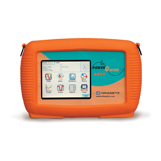
Dranetz PowerGuide 4400 User Manual (277 pages)
Power Quality Analyzer
Brand:
Dranetz
| Category:
Measuring Instruments
| Size: 4 MB
Table of Contents
Table of Contents
9
Safety Summary
4
Statements and Notices
7
Table of Contents
9
CHAPTER 1 - Getting Started
15
Overview
15
Table of Contents
16
Unpacking the 4400
17
Standard Accessories
18
4400 Controls, Indicators and Connectors
19
Top and Side Views
20
Front View
21
Bottom View
22
Rear View
23
Upgrading Firmware from a Data Card
24
4400 Features
26
Basic Operation
28
Power-On Sequence
29
Home Screen Icons
30
Overview
31
Connecting Voltage Measurement Cables
34
Connecting Current Probes
39
4400 Controls, Indicators, and Connectors
19
CHAPTER 2 - Voltage Measurement Cable and Current Probe Connections
31
CHAPTER 3 - View Real Time Data
43
Overview
43
Section a -Scope Mode
44
Overview
44
Turning Channels On/Off
45
Checking Input Range
46
Section B -Meter Mode
47
Overview
47
Standard Meter Tab
48
Distortion Meter Tab
50
Section C -Harmonics
52
Overview
52
Harmonic Graph
53
Harmonic Detail
54
Harmonic Options
55
Harmonic List
57
Section D -Voltage and Current Phasor
58
Overview
58
Phasor Screen
59
Phasor Rotation
60
Phasor Parameter/Channel Selection
62
C H a P T E R 4 Instrument Settings Overview
63
CHAPTER 4 - Instrument Settings
63
Overview
63
Access Instrument Settings Menu
64
Time and Date Settings
65
Select Language
67
Set Display Preferences
68
Touch Screen Calibration
69
Turn Threshold Beeper On/Off
71
Communications
72
Data Card
74
Reset to Factory Configurations
76
CHAPTER 5 - Start Menu
79
Overview
79
Section a -Automatic Setup
81
Section B -Wizard Setup
84
Overview
84
Monitoring
85
Current Probe Selection
86
Scale Factor Setup
88
Circuit Type Selection
90
Nominal Values
92
Mode of Operation
95
Monitoring Mode
96
Advanced Options
97
Site Name/Memory Card
98
Section C -Monitor same Circuit
102
Overview
102
Turning Monitoring On/Off
103
Monitoring at a Specified Time and Date
106
Modify Trigger Parameters and Intervals
111
Section D -Load Setup Template from Card
112
Section E -Load Data from Card
113
Loading Data from Card
113
Overview
113
Card Error Messages
114
CHAPTER 6 - Advanced Setup Options
115
Overview
115
Advanced Options Menu
116
Transient Limit
117
RMS Variation Limit
122
Waveform Capture
127
Characterizer Options
128
Journal Limit
129
Journal Interval for Timed Readings
132
EN50160 Power Quality (for Strict EN50160 Monitoring Only)
134
CHAPTER 7 - View Event Data
137
Overview
137
Section a -Events
140
Overview
140
Event Data Display
141
Event Activity Graph
142
Event List
143
Event Detail
145
Event Options
150
Section B -Trend
153
Overview
153
Trend Display
154
Trend Setup
155
CHAPTER 8 - Reports
159
Overview
159
Section a -EN50160
160
Overview
160
EN50160 Measurement Parameters
161
EN50160 Compliance Limits
163
Compliance Statistical Bar Chart
166
Compliance History
169
Event Satistics
171
Min/Max Table for Power Frequency and RMS Voltage
173
Section B -Status Report in Annunciator Panel
174
Overview
174
Panel Setup Options
175
Panel Operation
177
C H a P T E R 9 Downloading Events
181
CHAPTER 9 - Downloading Events
181
Overview
181
External Communication Interface
182
Connection Setup Via RS232
183
Connection Setup Via USB
184
Connection Setup Via Ethernet
185
Connection Setup Via Modem
187
Downloading Events Via Nodelink
190
Viewing Events Via Dranview
191
Dranview with HASP
192
Dranview ® with HASP
192
APPENDIX A - Optional Accessories
197
Overview
197
Hardware Accessories List & Descriptions
198
Software Accessories List
204
APPENDIX B - Technical Specifications
207
Overview
207
General
207
Interfaces
207
Measured Parameters
207
Computed Parameters
207
Parameter Settings in each Monitoring Mode
207
Technical Specifications
207
TR2500 Current Probe
217
TR2510 Current Probe
218
APPENDIX C - Battery Specifications and Replacement Procedure
219
Overview
219
Battery Specifications
219
Battery Safety Precautions
219
External Battery Charger
222
Battery Pack Replacement
224
APPENDIX D - User Replaceable Parts List
229
APPENDIX E - Common Circuit Connections
229
Overview
229
Verifying Voltage and Current Connections
233
Single Phase
235
Split Phase
236
Phase, Four Wire Wye
237
Phase (Floating or Grounded) Delta
238
Phase 2-Watt Delta
239
Generic Circuit
240
1/2 Element Without Voltage Channel B
241
1/2 Element Without Voltage Channel C
242
Connecting to a Potential Transformer (PT
243
Connecting to a Current Transformer (CT
245
Connecting to an Isolated Current Transformer (ISO
246
APPENDIX F - Event Classification
249
A P P E N D I X G Pg4400 Menu Structure
253
Home Screen
254
Start Menu - Automatic Setup
255
Start Menu - Monitor same Circuit G-5/A
258
In this Appendix
254
Instrument Settings
260
Circuit Type Selection
261
Scope Mode
262
Meter Mode - Standard
263
Meter Mode - Distortion
264
Harmonics
265
Phasor Display
266
Advanced Options - Transient Limit
267
Advanced Options - RMS Variation Limit
268
Advanced Options - Characterizer Options
269
Advanced Options - Waveform Capture
269
Advanced Options - Journal Limit
270
Advanced Options - Journal Interval
271
Advanced Options - EN50160
272
Events
273
Advertisement
Dranetz PowerGuide 4400 User Manual (270 pages)
Brand:
Dranetz
| Category:
Measuring Instruments
| Size: 4 MB
Table of Contents
Safety Summary
4
Statements and Notices
7
Table of Contents
9
CHAPTER 1 - Getting Started
15
Overview
15
Unpacking the 4400
17
Standard Accessories
18
4400 Controls, Indicators, and Connectors
19
Front View
19
Bottom View
19
Rear View
19
Upgrading Firmware from a Data Card
24
4400 Features
26
Basic Operation
28
Overview
31
Connecting Voltage Measurement Cables
34
Connecting Current Probes
39
CHAPTER 3 - View Real Time Data
43
Overview
43
Section a -Scope Mode
44
Overview
44
Turning Channels On/Off
45
Checking Input Range
46
Section B -Meter Mode
47
Overview
47
Standard Meter Tab
48
Distortion Meter Tab
50
Section C -Harmonics
52
Overview
52
Harmonic Graph
53
Harmonic Detail
54
Harmonic Options
55
Harmonic List
57
Section D -Voltage and Current Phasor
58
Overview
58
Phasor Screen
59
Phasor Rotation
60
Phasor Parameter/Channel Selection
62
Overview
63
Access Instrument Settings Menu
64
Time and Date Settings
65
Select Language
67
Set Display Preferences
68
Touch Screen Calibration
69
Turn Threshold Beeper On/Off
71
Communications
72
Data Card
74
Reset to Factory Configurations
76
CHAPTER 5 - Start Menu
79
Overview
79
Section a -Automatic Setup
81
Section B -Wizard Setup
84
Overview
84
Current Probe Selection
86
Scale Factor Setup
88
Circuit Type Selection
90
Nominal Values
92
Mode of Operation
95
Monitoring Mode
96
Advanced Options
97
Site Name/Memory Card
98
Section C -Monitor same Circuit
102
Overview
102
Turning Monitoring On/Off
103
Monitoring at a Specified Time and Date
106
Modify Trigger Parameters and Intervals
111
Section D -Load Setup Template from Card
112
Section E -Load Data from Card
113
Overview
113
Loading Data from Card
113
Card Error Messages
114
Overview
115
Advanced Options Menu
116
Transient Limit
117
RMS Variation Limit
122
Waveform Capture
127
Characterizer Options
128
Journal Limit
129
Journal Interval for Timed Readings
132
EN50160 Power Quality (for Strict EN50160 Monitoring Only)
134
EN50160 Power Quality
134
CHAPTER 7 - View Event Data
136
Overview
136
Section a -Events
139
Overview
139
Event Data Display
140
Event Activity Graph
141
Event List
142
Event Detail
144
Event Options
149
Section B -Trend
152
Overview
152
Trend Setup
154
CHAPTER 8 - Reports
157
Overview
157
Section a -EN50160
158
Overview
158
EN50160 Measurement Parameters
159
EN50160 Compliance Limits
161
Compliance Statistical Bar Chart
164
Compliance History
167
Event Satistics
169
Event Statistics
170
Min/Max Table for Power Frequency and RMS Voltage
171
Section B -Status Report in Annunciator Panel
172
Overview
172
Panel Setup Options
173
Panel Operation
175
Overview
179
External Communication Interface
180
Connection Setup Via RS232
181
Connection Setup Via USB
182
Connection Setup Via Ethernet
183
Downloading Events Via Nodelink
188
Viewing Events Via Dranview
189
Dranview with HASP
190
Dranview ® with HASP
190
APPENDIX A - Optional Accessories
194
Overview
194
Hardware Accessories List & Descriptions
195
Software Accessories List
201
APPENDIX B - Technical Specifications
203
Overview
203
General
204
Interfaces
205
Measured Parameters
206
Computed Parameters
207
Parameter Settings in each Monitoring Mode
211
TR2500 Current Probe
213
TR2510 Current Probe
214
APPENDIX C - Battery Specifications and Replacement Procedure
215
Overview
215
Battery Specifications
216
Battery Safety Precautions
217
External Battery Charger
218
Battery Pack Replacement
220
APPENDIX E - Common Circuit Connections
223
Overview
223
Verifying Voltage and Current Connections
227
Single Phase
227
Single Phase
229
Split Phase
230
Phase, Four Wire Wye
231
Phase (Floating or Grounded) Delta
232
Phase 2-Watt Delta
233
Generic Circuit
234
1/2 Element Without Voltage Channel B
235
1/2 Element Without Voltage Channel C
236
Connecting to a Potential Transformer (PT
237
Connecting to a Current Transformer (CT
239
Connecting to an Isolated Current Transformer (ISO
240
APPENDIX F - Event Classification
243
Home Screen
247
Start Menu - Automatic Setup
248
Start Menu - Monitor same Circuit G-5/A
251
Instrument Settings
253
Circuit Type Selection
254
Scope Mode
255
Meter Mode - Standard
256
Meter Mode - Distortion
257
Harmonics
258
Phasor Display
259
Advanced Options - Transient Limit
260
Advanced Options - RMS Variation Limit
261
Advanced Options - Waveform Capture
262
Advanced Options - Characterizer Options
262
Advanced Options - Journal Limit
263
Advanced Options - Journal Interval
264
Advanced Options - EN50160
265
Events
266
Advertisement
Related Products
Dranetz DBPG106
Dranetz DBPG10PKG
Dranetz DBPG500PKG
Dranetz DBPGFLEX3KPKG
Dranetz DBPGFLEX6KPKG
Dranetz DBPV10
Dranetz DBPV500
Dranetz DBPVFLEX6K
Dranetz Encore 61000
Dranetz Categories
Measuring Instruments
Monitor
Battery Charger
Multimeter
Control Unit
More Dranetz Manuals
Login
Sign In
OR
Sign in with Facebook
Sign in with Google
Upload manual
Upload from disk
Upload from URL