Sign In
Upload
Manuals
Brands
Danfoss Manuals
Switch
PVG 32
Danfoss PVG 32 Manuals
Manuals and User Guides for Danfoss PVG 32. We have
10
Danfoss PVG 32 manuals available for free PDF download: Service And Parts Manual, Technical Information, Service Manual, Application Manual, Installation Manual
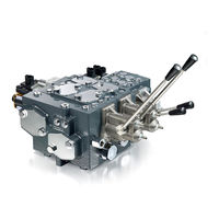
Danfoss PVG 32 Service And Parts Manual (144 pages)
Proportional Valve Group
Brand:
Danfoss
| Category:
Control Unit
| Size: 26.94 MB
Table of Contents
Table of Contents
3
Safety in Systems
5
PVG 16/32 Sectional Drawings
7
PVG 128/256 Sectional Drawing
10
Installation
11
PVG 16 Installation
11
Standard Assembly
11
Plug Orientation
12
Maximum Flow Setting
13
Pressure Setting and Adjustment
14
Installation of Lever
16
Bleeding
17
PVE Series 6
18
Relevant Technical Data
19
Pvhc
21
LED Characteristics
22
Standard Main Spool Assembly
23
PVG 32 Installation
24
Standard Assembly
24
Plug Orientation
25
Maximum Flow Setting
26
Pressure Setting and Adjustment
27
Installation of Lever
29
Bleeding
29
PVEP Series 4
30
PVED-CC Series 5
32
PVE Series 7
34
Pvhc
38
Standard Main Spool Assembly
40
PVG 128/256 Installation
41
Standard Assembly
41
Plug Orientation
42
Pump Side Module
43
Pressure Setting
44
Installation of Lever
45
PVE Series 7
46
Pvhc
49
Standard Main Spool Assembly
51
Service Parts
52
PVG Acronyms Found in Service Parts
52
PVG 16 Service Parts
53
Pump Side Module, PVP
53
Pump Side Module PVPV
56
Electrical LS Pressure Unloading Valve, PVPX
57
PVB with LS Port
59
PVB with PVLP/PVLA, Basic Module
61
PVLP Shock and PVLA, Suction Valves
63
PVBS, Main Spool
64
PVM Mechanical Activation
65
PVMD Cover
66
PVH Hydraulic Actuation
67
PVHC High Current Actuation
68
PVE Series 6 PVEO On/Off Actuator
69
PVE Series 6 PVEA Proportional Actuator
70
PVS/PVSI End Plates
71
PVAS Stay Bolts
73
Seal Kits
74
PVG 32 Service Parts
75
Pump Side Module PVP
75
Pump Side Module PVPV
78
Pump Side Module PVPM/PVPVM
80
Electrical LS Pressure Unloading Valve, PVPX
81
External Pilot Pressure Adapter, PVPC
83
PVB Basic Module
84
Basic Module, PVBZ
87
PVBZ with PVBD Diverter
89
PVLP Shock and PVLA, Suction Valves
91
PVBS Main Spool
92
PVM Medchanical Activation
93
PVMD, PVMR and PVMF Covers
94
PVH Hydraulic Actuation
96
Electrical Actuation PVHC
97
PVDI Directional Indication
98
PVS/PVSI End Plates
99
PVSI, PVSD, PVST End Plates
101
PVAS Stay Bolts
104
Seal Kits
105
PVE Series 4 PVEO
106
PVE Series 4 PVEA
107
PVE Series 4 PVEM
108
PVE Series 4 PVEP
109
PVE Series 4 PVEU
110
PVE Series 4 PVEH
111
PVE Series 4 PVES
112
PVED-CC Series 5
113
PVE Series 7 PVEO
114
PVE Series 7 PVEO-HP
115
PVE Series 7 PVEM
116
PVE Series 7 PVEA
117
PVE Series 7 PVEH
118
PVE Series 7 PVES
119
PVG 128/256 Service Parts
120
Pump Side Module, PVPV
120
PVB 128, Basic Module
122
PVB 256, Basic Module
124
PVLP Shock and PVLA, Suction Valves
126
PVBS Main Spool
127
PVM Mechanical Activation
128
PVMD Cover
129
PVH Hydraulic Actuation
130
PVHC High Current Actuation
131
PVEO On/Off Actuator
133
PVEH Proportional Actuator
135
PVS End Plates
137
PVAS Stay Bolts
139
Seal Kits
140
Advertisement
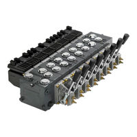
Danfoss PVG 32 Technical Information (76 pages)
Proportional Valve Group
Brand:
Danfoss
| Category:
Control Unit
| Size: 8.29 MB
Table of Contents
Table of Contents
3
General Description
5
Features of PVG 32
5
PVG Modules
5
PVP, Pump Side Modules
5
PVB, Basic Modules
5
August
5
Actuation Modules
6
Remote Control Units
6
PVG 32 with Open Center PVP
7
PVG 32 with Closed Center PVP
8
PVG 32 Sectional View
9
Load Sensing for Variable Displacement Pump Supply
9
Safety in Application
11
Control System Example
12
Examples of Wiring Block Diagram
14
Function
16
Load Sensing Controls
16
LS Control with Bleed Orifice (Do Not Use with PVG Valves)
16
Integral PC Function
16
Load Sensing System Characteristics
16
Remote Pressure Compensated Controls
16
Remote Pressure Compensated System Characteristics
17
Typical Applications for Remote Pressure Compensated Systems
17
PVG 32 Main Spool with Pressure Compensated Control
17
Pressure Compensated System Characteristics
18
Typical Applications for Pressure Compensated Systems
18
PVPC Adapter for External Pilot Oil Supply
18
PVPC with Check Valve for Open Center PVP
18
PVPC Without Check Valve for Open or Closed Center PVP
19
PVMR, Friction Detent
21
PVMF, Mechanical Float Position Lock
21
PVBS, Main Spools for Flow Control (Standard)
21
PVBS, Main Spools for Flow Control (Linear Characteristic)
21
PVBS, Main Spools for Pressure Control
22
Background
22
Principle
22
Application
23
Sizing
23
Limitation
24
PVPX, Electrical LS Unloading Valve
24
PVG 32 Technical Data
25
PVH, Hydraulic Actuation
26
PVM, Mechanical Actuation
26
PVE, Electrical Actuation
26
PVPX, Electrical LS Unloading Valve
29
Electrical Actuation
30
Electrical Control of PVG
30
Closed Loop Control
31
Pveo
32
Pvem
32
Pvea, Pveh, Pves, Pveu
33
Pvep
33
PVED-CC and PVED-CX
33
Pvhc
34
Technical Characteristics
36
General
36
PVP, Pump Side Module
36
PVB, Basic Modules Oil Flow Characteristics
36
Pressure-Compensated PVB, Open Center PVP
37
PVB Without Pressure Compensation, Open Center PVP
38
PVB Without Pressure Compensation, Closed Center PVP
39
PVLP, Shock and PVLA, Suction Valves
41
Pressure Build-Up for Pressure Controlled Spools
41
Pressure Control Spool Flow Characteristics
41
Examples of How to Use the Characteristics for Pressure Control Spools
42
Characteristics for Float Position Main Spools
43
Hydraulic Systems
45
Manually Actuated PVG 32 - Fixed Displ. Pump
45
Electrically Actuated PVG 32 - Variable Displ. Pump
46
Other Operating Conditions
47
Oil
47
Particle Content, Degree of Contamination
47
Filtration
47
Dimensions
49
PVM, Control Lever Positions
50
Surface Treatment
51
Modules Symbols, Description and Code Numbers
52
PVP, Pump Side Modules
52
PVB, Basic Modules
54
PVLA, Suction Valve (Fitted in PVB)
56
PVLP, Shock and Suction Valve (Fitted in PVB)
56
PVM, Mechanical Actuation
57
PVH, Hydraulic Actuation
58
PVS, End Plate
58
PVAS, Assembly Kit
58
PVPX, Electrical LS Unloaded Valve
58
PVPC, Plug for External Pilot Oil Supply
59
Module Selection Chart
60
Standard FC Spools
60
Standard FC Spools, Hydraulic Actuation
61
FC Spools for Mechanical Float Position, PVMF
61
FC Spools for Friction Detent, PVMR
62
FC Spools with Linear Flow Characteristic
62
Standard PC Spools
63
Standard PC Spools, Hydraulic Actuation
64
PVB, Basic Valves
65
PVP, Pump Side Module
66
PVE, Electrical Actuation
68
Order Specification
70
Standard and Option Assembly
70
Reordering
70
Pressure Setting Limits
70
PVG 32 Specification Sheet
72
Danfoss PVG 32 Technical Information (68 pages)
Proportional Valve Group
Brand:
Danfoss
| Category:
Control Unit
| Size: 7.86 MB
Table of Contents
Table of Contents
3
PVG General Description
5
Features of PVG 32
5
PVG Modules
6
PVP, Pump Side Modules Overview
6
PVB, Basic Modules
6
Actuation Modules
6
Remote Control Units
7
Open Center PVP
8
Closed Center PVP
8
Sectional View
9
Load Sensing for Variable Displacement Pump Supply
10
Safety in Application
11
Example of a Control System for Manlift
12
Examples of Wiring Block Diagram
14
Function
16
Load Sensing Controls
16
LS Control with Bleed Orifice (Do Not Use with PVG Valves)
16
Integral PC Function
16
Load Sensing System Characteristics
16
Remote Pressure Compensated Controls
17
Remote Pressure Compensated System Characteristics
17
Typical Applications for Remote Pressure Compensated Systems
17
PVPC with Check Valve for Open Center PVP
17
PVPC Without Check Valve for Open or Closed Center PVP
19
PVMR, Friction Detent
20
PVMF, Mechanical Float Position Lock
20
PVBS, Main Spools for Flow Control (Standard)
20
PVBS, Main Spools for Flow Control (Linear Characteristic)
21
PVBS, Main Spools with Pressure Compensated Control
22
Pressure Compensated System Characteristics
22
Typical Applications for Pressure Compensated Systems
22
PVBS, Main Spools for Pressure Control
23
Background
23
PVG 32 Principle
23
Pressure Controlled Spool Application
24
Sizing
25
Limitation
25
PVPX, Electrical LS Unloading Valve
26
PVG 32 Technical Data
27
PVM Operating Force
28
PVH, Hydraulic Actuation
28
PVE Actuation Literature Reference
28
Technical Characteristics
29
PVP Pressure Relief Valve Characteristics
29
PVB, Basic Modules Oil Flow Characteristics
30
Pressure-Compensated PVB, Open Center PVP
31
PVB Without Pressure Compensation, Open Center PVP
32
PVB Without Pressure Compensation, Closed Center PVP
34
PVLP, Shock and PVLA, Suction Valves
36
Pressure Control Spool Flow Characteristics
36
Pressure Build-Up for Pressure Controlled Spools
38
Examples of How to Use the Characteristics for Pressure Control Spools
38
Characteristics for Float Position Main Spools
39
Hydraulic Systems
41
Manually Actuated PVG 32 - Fixed Displ. Pump
41
Electrically Actuated PVG 32 - Variable Displ. Pump
42
Fluid Specifications
43
Oil
43
Mineral Oil
43
Non-Flammable Fluids
43
Filtration
43
Dimensions and Ports Description
44
PVM, Control Lever Positions
46
Surface Treatment
46
Parts Description and Code Numbers
47
PVP Schematics and Code Numbers
47
PVB, Basic Module Code Numbers
50
PVLA, Suction Valve (Fitted in PVB)
53
PVLP, Shock and Suction Valve (Fitted in PVB)
53
PVM, PVMD, PVMR, and PVMF Code Numbers
54
PVH, Hydraulic Actuation Code Numbers
55
PVE Actuation Literature Reference
55
PVS, End Plate
55
PVAS, Assembly Kit Code Numbers
56
PVPX, Electrical LS Unloaded Valve
56
PVPC, Plug for External Pilot Oil Supply
57
Standard FC Spools
57
Standard FC Spools, Hydraulic Actuation
59
FC Spools for Mechanical Float Position, PVMF
60
FC Spools for Friction Detent, PVMR
60
FC Spools with Linear Flow Characteristic
61
Standard PC Spools
61
Standard PC Spools, Hydraulic Actuation
63
Order Specification
64
PVG 32 Order Specification
64
Reordering
64
Pressure Setting Limits
65
PVG 32 Specification Sheet
66
Standard and Option Assembly
66
Advertisement
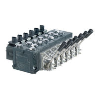
Danfoss PVG 32 Service Manual (44 pages)
Proportional Valve Group
Brand:
Danfoss
| Category:
Control Unit
| Size: 5.45 MB
Table of Contents
Table of Contents
3
Overview
5
General Instructions
5
Remove the Unit
5
Keep It Clean
5
Replace All O-Rings and Gaskets
5
Secure the Unit
5
February
5
Safety Precautions
6
Unintended Machine Movement
6
Flammable Cleaning Solvents
6
Fluid under Pressure
6
Personal Safety
6
Hazardous Material
6
Acronyms
6
Operation
8
PVG 32 Group with Open Center PVP (PVB with Flow Control Spool)
8
PVG 32 Group with Closed Center PVP (PVB with Flow Control Spool)
8
PVG 32 Sectional Drawing
9
PVPC Plug for External Pilot Oil Supply
9
Friction Detent
11
PVBS, Main Spools for Flow Control (Standard)
12
PVBS, Main Spools for Flow Control (with Linear Characteristics)
12
PVBS, Main Spools for Pressure Control
12
PVPX Electrical LS Unloading Valve
13
System Troubleshooting
14
Overview
14
Troubleshooting a PVG Valve
14
No Cylinder/Motor Response in Either Direction When Remote Controller Is Actuated
15
Cylinder/Motor Responds in One Direction Only
16
Main Valve Spool Moves Without Oil Passing to Cylinder/Motor
16
Cylinder/Motor Operates Without Remote Controller Being Operated
17
Cylinder/Motor Responds Slowly to Remote Electrical or Hydraulic Controller Actuation
17
Erratic Cylinder/Motor Response to Electrical or Hydraulic Controller Operation
17
Hydraulic Oil Supply
18
Electrical Supply
18
Hydraulic (Remote) Pilot Control Pressure
19
PVG 32 Component Troubleshooting
20
Pressure Relief Valve
20
Pressure Reducing Pilot Valve
20
Pressure Gauge Connection
21
Open Center Plug
22
Closed Center Plug and Orifice
23
Pressure Adjustment Spool
24
LS Connection
25
LS Signal
25
10. Shuttle Valve
26
LS Pressure Limiting Valve
27
LS A, B Shuttle
27
Main Spool
28
Shock and Anti-Cavitation Valve PVLP
29
Pressure Compensator
30
Load Drop Check Valve
31
Maximum Oil Flow Adjustment Screws for Ports a and B
32
PVM Module
33
PVS Module
34
PVPVM Module
35
PVAS Module
36
PVPX LS Unloading Valve
37
PVEM, PVEA, PVEH, PVES Electrical Actuators
38
Troubleshooting Considerations
38
PVEO ON/OFF Electrical Actuator
39
PVPC Plug for External Pilot Control
42
PVMR Friction Module
42
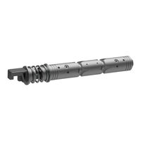
Danfoss PVG 32 Technical Information (36 pages)
Proportional Valve Group AG modules
Brand:
Danfoss
| Category:
Control Unit
| Size: 3.25 MB
Table of Contents
Table of Contents
3
Literature Reference for PVG Products
4
Introduction
5
Short Overview
5
Hitch Control
5
Function
6
Warning
6
PVG 32 Cross-Sectional View
7
Technical Data
8
PVG 32 Technical Parameters
8
PVBZ Basic Module for EH Auxiliary Valve Functions
9
PVBD, PVBZ with Optional Diverter Feature
10
Principle Description of PVBD Diverter
10
PVBZ-HS/HD, Hitch Control Valves
11
General Introduction
11
PVBZ-HS Basic Module (Hitch Single-Acting)
11
PVBZ-HD Basic Module (Hitch Double-Acting)
12
PVP with Integrated HPCO
14
Modules and Code Numbers
15
PVB, Inlet Basic Modules
15
PVBZ Auxiliary Modules
16
PVBZ-HS/-HD Modules, PVBD Diverter, Multi-Valve (for PVBZ-HD)
17
PVBS Spools
19
Pve
19
End Plates Compatible with Metric PVG 32 Program
20
Activation Characteristics
22
Characteristic of Oil Flow, Spool Travel and Voltage
22
Pressure Drop Characteristics
23
Pressure Drop Characteristics of Float Spools
23
Single Acting Spools Characteristics for PVBZ-HS
26
Pressure Drop Characteristic in Lower Mode Position, Max. Spool Travel
26
Spools Characteristics for PVBZ-HD
26
Dimensions and Schematic Examples
29
Drawings for 5-Section Group
29
Drawings for 3-Section Group
30
Drawings for 2-Section Group
32
Danfoss PVG 32 Service Manual (28 pages)
Proportional Valves
Brand:
Danfoss
| Category:
Control Unit
| Size: 9 MB
Table of Contents
Table of Contents
3
General Information
4
November
4
PVG General Description
5
Features of PVG 16 and PVG 32
5
PVG Modules
6
PVP, Pump Side Modules Overview
6
PVB, Basic Modules
6
Actuation Modules
6
PVG 16, PVG 32 and Open Circuit Load Sense Example
7
Load Sensing Controls
8
LS Control with Bleed Orifice (Do Not Use with PVG Valves)
8
Integral PC Function
8
Load Sensing System Characteristics
8
PVBS, Main Spools with Pressure Compensated Control
9
Pressure Compensated System Characteristics
9
Typical Applications for Pressure Compensated Systems
9
Remote Pressure Compensated Controls
10
Remote Pressure Compensated System Characteristics
10
Typical Applications for Remote Pressure Compensated Systems
10
Open Center PVP
11
Closed Center PVP
11
Sectional View
11
Safety in Application
13
Example of a Control System for Manlift
13
Examples of Wiring Block Diagram
15
Assembly Instructions
17
PVG 16 and 32 General Conditions
17
Assembly
17
Testing
22
PVG 16 and 32 Leak Test
22
Pressure Setting after Assembly
22
PVG 16 and 32 Function Testing
23
Recommended Equipment and Hand Tools to Assemble PVG 16 and PVG 32
24
Test Report
25
Order Specifications
26
Danfoss PVG 32 Installation Manual (10 pages)
Proportional Valve Group
Brand:
Danfoss
| Category:
Control Unit
| Size: 2.13 MB
Table of Contents
Installation and Plug Orientation
2
Connection – PVP, Pump Side Module
2
Connection - PVB, Basic Module
3
Connection Threads Type G
3
UN and UNF Connection Threads – O-Ring Boss Port
3
Rated Pressure
3
PVG - Standard Mounting
4
PVG - Option Mounting
4
PVG - Bleeding
5
PVG - Pressure Setting PVP, LS a , LS B
5
PVM - Installation of Lever
6
PVE - Installation
6
PVE Connector Variants
7
PVE Operating Conditions
8
PVE Control Specifications
8
PVE LED Characteristics
9
Danfoss PVG 32 Application Manual (13 pages)
Using flow or pressure control spools
Brand:
Danfoss
| Category:
Industrial Equipment
| Size: 3.14 MB
Table of Contents
About this Document
3
Important User Information
3
Application Overview
4
Functionality of a Flow Control Spool
5
Flow Control Spools in Oscillating Systems
6
Functionality of a Pressure Control Spool
7
Pressure Control Spools in Oscillating Systems
9
Pressure Control Spools with Counterbalance Valves
10
Danfoss PVG 32 Service Manual (15 pages)
Brand:
Danfoss
| Category:
Control Unit
| Size: 13.46 MB
Table of Contents
Troubleshooting
8
Installation
9
Operation
10
Low Volume
11
Maintenance
11
Danfoss PVG 32 Installation Manual (10 pages)
Proportional Valve
Brand:
Danfoss
| Category:
Switch
| Size: 2.69 MB
Advertisement
Related Products
Danfoss PVG 120
Danfoss PVG 16 PVH/Covers
Danfoss PVG 100
Danfoss PVG 128
Danfoss PVG 256
Danfoss PVG 16 PVP
Danfoss PVG 16 PVS
Danfoss PVG 16 PVHC
Danfoss PVG 16 PVAS
Danfoss PVG 16 PVE
Danfoss Categories
Controller
DC Drives
Thermostat
Control Unit
Water Pump
More Danfoss Manuals
Login
Sign In
OR
Sign in with Facebook
Sign in with Google
Upload manual
Upload from disk
Upload from URL