Danfoss PVG 32 Service Manual
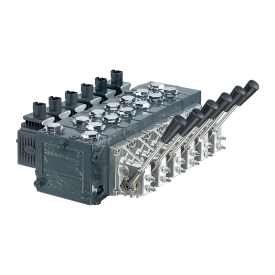
Proportional valve group
Hide thumbs
Also See for PVG 32:
- Technical information (76 pages) ,
- Service manual (15 pages) ,
- Application manual (13 pages)
Table of Contents
Advertisement
Advertisement
Table of Contents
Troubleshooting

Related Manuals for Danfoss PVG 32


Summary of Contents for Danfoss PVG 32
- Page 1 Service Manual PVG 32 powersolutions.danfoss.com...
- Page 2 Table of revisions Date Changed February 2017 Updated with PVE Series 7 0301 May 2014 Converted to Danfoss layout – DITA CMS Feb 2006 - Aug 2013 Various changes AB - BA 11039167 | AX00000031en-US0301 © Danfoss | February 2017...
-
Page 3: Table Of Contents
Acronyms......................................6 Operation PVG 32 group with open center PVP (PVB with flow control spool)................8 PVG 32 group with closed center PVP (PVB with flow control spool)................8 PVG 32 sectional drawing................................9 PVPC plug for external pilot oil supply............................. 9 Friction detent....................................11 PVBS, main spools for flow control (standard)........................ - Page 4 Service Manual PVG 32 Proportional Valve Group Contents PVEM, PVEA, PVEH, PVES electrical actuators........................38 Troubleshooting Considerations..............................38 PVEO ON/OFF electrical actuator............................. 39 PVPC plug for external pilot control............................42 PVMR Friction Module..................................42 11039167 | AX00000031en-US0301 © Danfoss | February 2017...
-
Page 5: Overview
Introduction Overview This manual includes information for servicing PVG 32 valves. It includes a description of the units and their individual components, troubleshooting information, and minor repair procedures. Performing minor repairs may require removal from the vehicle/machine. Thoroughly clean the unit before beginning maintenance or repair activities. -
Page 6: Safety Precautions
Service Manual PVG 32 Proportional Valve Group Introduction Safety precautions Always consider safety precautions before beginning a service procedure. Protect yourself and others from injury. Take the following general precautions whenever servicing a hydraulic system. Unintended machine movement Warning Unintended movement of the machine or mechanism may cause injury to the technician or bystanders. - Page 7 Service Manual PVG 32 Proportional Valve Group Introduction PVPX, LS LS Unloading valve PVPC Plug for external pilot oil supply PVBS Main spool Mechanical activation PVMD Cover for mechanical activation Cover for hydraulic activation PVMF Cover for mechanical float PVMR...
-
Page 8: Operation
PVG 32 Proportional Valve Group Operation PVG 32 group with open center PVP (PVB with flow control spool) When the pump starts, and the main spools in the individual basic modules (11) are in the neutral position, oil flows from the pump, through connection P, across the pressure adjustment spool (6) to tank. -
Page 9: Pvg 32 Sectional Drawing
PVPC with check valve for open center PVP PVPC, with check valve, is used in systems where it is necessary to operate the PVG 32 valve by means of the electrical remote control without pump flow. When the external solenoid valve is opened, oil from 11039167 | AX00000031en-US0301 | 9 ©... - Page 10 PVPC without check valve for open center PVP PVPC, without check valve, is used in systems where it is necessary to supply the PVG 32 valve with oil from a manually operated emergency pump without directing oil flow to the pilot oil supply (oil consumption about 1 l/min) [0.25 US gal/min].
-
Page 11: Friction Detent
Service Manual PVG 32 Proportional Valve Group Operation Friction detent PVMR Friction detent The friction detent PVMR allows the directional spool to be held in any position, resulting in infinitely variable, pressure compensated flow. The spool position will be held indefinitely without the necessity of holding the mechanical lever. -
Page 12: Pvbs, Main Spools For Flow Control (Standard)
Service Manual PVG 32 Proportional Valve Group Operation PVMF (Standard assembly) (Optional assembly) PVBS, main spools for flow control (standard) When using standard flow control spools, the pump pressure is determined by the highest load pressure. This is done either via the pressure adjustment spool in open center PVP (fixed displacement pumps) or via the pump regulator (variable displacement pumps). -
Page 13: Pvpx Electrical Ls Unloading Valve
Service Manual PVG 32 Proportional Valve Group Operation Due to these factors use pressure control spools only when you know for certain that problems with stability will arise – or already have arisen. Use LS when pressure stability is an issue. -
Page 14: System Troubleshooting
Confirm that valve is built properly according to the specification sheet. If necessary, install a lever to the valve to verify proper mechanical function. Refer to PVG 32 Technical Information Manual 520L0344 for valve configuration information. Refer to PVG 32 Parts Manual 11006794 for part numbers. -
Page 15: No Cylinder/Motor Response In Either Direction When Remote Controller Is Actuated
Service Manual PVG 32 Proportional Valve Group System Troubleshooting Troubleshooting flow chart Problem? Problem? Problem? Mechanical Mechanical Mechanical Mechanical Mechanical Mechanical Hydraulic Hydraulic Hydraulic Hydraulic Hydraulic Hydraulic Hydraulic Hydraulic Electrical Electrical Electrical Electrical Electrical Electrical Electrical Electrical Electronic Electronic Electronic... -
Page 16: Cylinder/Motor Responds In One Direction Only
Service Manual PVG 32 Proportional Valve Group System Troubleshooting Cylinder/motor responds in one direction only Cause Check Corrective action Verify if fault is mechanical, electrical Operate manual lever in both directions to confirm if If moving the manual lever operates the cylinder/motor... -
Page 17: Cylinder/Motor Operates Without Remote Controller Being Operated
Service Manual PVG 32 Proportional Valve Group System Troubleshooting Cause Check Corrective action Cylinder/motor load too high for Check load pressure at PVB-LS port Reduce load pressure if exceeds maximum pressure limit pressure settings of system of the system Maximum system pressure should be approx. 25... -
Page 18: Hydraulic Oil Supply
Service Manual PVG 32 Proportional Valve Group System Troubleshooting Cause Check Corrective action Main spool position feedback Check feedback pin for damage Replace PVE transducer signal incorrect Contamination in hydraulic oil Take oil sample Flush complete system. Fill reservoir with clean filtered fluid per OEM... -
Page 19: Hydraulic (Remote) Pilot Control Pressure
Service Manual PVG 32 Proportional Valve Group System Troubleshooting Cause Check Corrective action Incorrect signal voltage Check voltage levels at solenoid plug Proportional operation - Refer to Troubleshooting Considerations Udc: Supply voltage (100%) Us: Supply signal voltage (25-50-75%) Ground: Live or ground connection... -
Page 20: Pvg 32 Component Troubleshooting
Service Manual PVG 32 Proportional Valve Group PVG 32 Component Troubleshooting Pressure relief valve Description: Adjustable relief valve. Adjustment range 50 Bar [700 PSI] to 350 Bar [5000 PSI]. Location: The relief is in all PVP Inlet modules Function: Provides maximum pressure setting above pump pressure setting 30 Bar [450 PSI] Delta for... -
Page 21: Pressure Gauge Connection
Service Manual PVG 32 Proportional Valve Group PVG 32 Component Troubleshooting Serviceability: All internal components can be removed from the cavity, cleaned, inspected and reassembled back into the valve 1. Use a 6 mm internal hex wrench to remove the plug, and then remove all the other internal components in the cavity 2. -
Page 22: Open Center Plug
Service Manual PVG 32 Proportional Valve Group PVG 32 Component Troubleshooting Pressure gauge port Pressure gauge port P107 735E When valve is equipped with the PVPC option use a running tee to measure pressure. Torque tee to hose adaptor torque specification. -
Page 23: Closed Center Plug And Orifice
Service Manual PVG 32 Proportional Valve Group PVG 32 Component Troubleshooting Serviceability: Open center plug is serviceable. 1. Use a 6 mm internal hex to remove cavity plug from valve. 2. Use a 3 mm internal hex to remove open center plug. -
Page 24: Pressure Adjustment Spool
Service Manual PVG 32 Proportional Valve Group PVG 32 Component Troubleshooting Closed center plug Plug 6 mm 35 Nm [308 lbf•in] O-ring Seal Closed center plug 4 mm Orifice 8 Nm [70 lbf•in] 2.5 mm 4 Nm [35 lbf•in] P107 737E Pressure adjustment spool Description: Main pump flow unloading spool. -
Page 25: Ls Connection
Service Manual PVG 32 Proportional Valve Group PVG 32 Component Troubleshooting LS connection Description: Port for LS signal for LS (static) option only controller for variable flow pump. Location: PVP (inlet) module. Function: Provide a signal to the variable pump controller to create a pressure differential to have the pump come on stroke for a closed center system. -
Page 26: 10. Shuttle Valve
Service Manual PVG 32 Proportional Valve Group PVG 32 Component Troubleshooting Function: Directs the highest load pressure to either OC or CC pump control to satisfy the operating valve section. Failure mode Cause Corrective action No pump pressure developed in LS passages blocked or restricted Disassemble valve. -
Page 27: Ls Pressure Limiting Valve
Service Manual PVG 32 Proportional Valve Group PVG 32 Component Troubleshooting Shuttle valve Ball should move Exploded view shows internal parts. freely behind disk. Do not disassemble valve. Ball should move freely behind disk. P107 804 LS pressure limiting valve Description: Optional adjustable pilot relief valve. -
Page 28: Main Spool
Service Manual PVG 32 Proportional Valve Group PVG 32 Component Troubleshooting Failure mode Cause Corrective action Will not build pressure in A or B Contamination preventing shuttle ball from Replace complete PVB module work port building load sense relief pressure... -
Page 29: Shock And Anti-Cavitation Valve Pvlp
Service Manual PVG 32 Proportional Valve Group PVG 32 Component Troubleshooting 5. Install plug with a 11 mm or 12 mm open end wrench. Torque to 8 Nm [70 lbf•in]. 6. Install centering spring and tension rod using a 13 mm open end wrench and torque to 8 Nm [70 lbf•in]. -
Page 30: Pressure Compensator
Service Manual PVG 32 Proportional Valve Group PVG 32 Component Troubleshooting PVLP valve Plug 13 mm 36 Nm [310 lbf•in] Do not try to adjust or disassemble PVLP P107 743E Pressure compensator Description: Optional pressure compensator maintains a constant pressure drop across the main spool. -
Page 31: Load Drop Check Valve
Service Manual PVG 32 Proportional Valve Group PVG 32 Component Troubleshooting Pressure compensator valve P107 744E Pressure compensator spool Pressure compensator spool P107 822 Load drop check valve Description: Keeps the load from dropping when transitioning from spool neutral to lifting the load. -
Page 32: Maximum Oil Flow Adjustment Screws For Ports A And B
Service Manual PVG 32 Proportional Valve Group PVG 32 Component Troubleshooting Load drop check valve P107747E Load drop check valve Load drop check valve P107 748E Maximum oil flow adjustment screws for ports A and B Description: Optional mechanical flow limiter. -
Page 33: Pvm Module
Service Manual PVG 32 Proportional Valve Group PVG 32 Component Troubleshooting Adjusting screws for ports A and B For standard mount, top adjusting screw is B and bottom adjusting screw is A P107 816E PVM module Description: Manual control lever. -
Page 34: Pvs Module
Service Manual PVG 32 Proportional Valve Group PVG 32 Component Troubleshooting PVM module O-rings Seal Screw (x4) 5 mm 8 Nm [70 lbf•in] P197 806E PVS module Description: End cover. Location: Mounted on the last PVB of the valve stack. -
Page 35: Pvpvm Module
PVG 32 Proportional Valve Group PVG 32 Component Troubleshooting PVS plugs P107 707E For specifications and operating parameters on PVG 32 valves, refer to PVG 32 Technical Information Manual 520L0344. PVPVM module Description: Mid-inlet module only for closed center systems. -
Page 36: Pvas Module
Service Manual PVG 32 Proportional Valve Group PVG 32 Component Troubleshooting PVPVM module Do not try to adjust or disassenmble PVLP 13 mm 40 Nm [354 lbf•in] Plug P107 808E PVAS module Description: Tie rod kit. Location: Through the valve stack. -
Page 37: Pvpx Ls Unloading Valve
Service Manual PVG 32 Proportional Valve Group PVG 32 Component Troubleshooting If replacing seal kit, replace tie rods also P107 817E PVPX LS unloading valve Refer to PVPX Electrical LS unloading valve for valve operation. Description: Optional two way two position solenoid. -
Page 38: Pvem, Pvea, Pveh, Pves Electrical Actuators
Service Manual PVG 32 Proportional Valve Group PVG 32 Component Troubleshooting PVEM, PVEA, PVEH, PVES electrical actuators Description: Proportional electrical actuator. Location: On the end of the main spool of the PVB. Function: Convert an electrical command to move the main spool to a set position. -
Page 39: Pveo On/Off Electrical Actuator
Service Manual PVG 32 Proportional Valve Group PVG 32 Component Troubleshooting Checking input control signal: 1. Install volt meter to ground pin connection and signal pin with PVE in circuit. 2. Turn the power on for the electrical controller. 3. Actuate the electrical controller and read the voltage. - Page 40 Service Manual PVG 32 Proportional Valve Group PVG 32 Component Troubleshooting Checking input control signal 1. Install a volt meter to the ground pin connection and to the signal pin. 2. Turn the power on for the electrical controller. 3. Actuate the electrical controller and read the voltage.
- Page 41 Service Manual PVG 32 Proportional Valve Group PVG 32 Component Troubleshooting PVEP Connector Pin 1 Pin 2 Pin 3 Pin 4 Pin 5 Pin 6 1x6 DEU PWM_A Error PWM_B PVED-CC Connector Pin 1 Pin 2 Pin 3 Pin 4...
-
Page 42: Pvpc Plug For External Pilot Control
Service Manual PVG 32 Proportional Valve Group PVG 32 Component Troubleshooting PVPC plug for external pilot control Description: Pilot oil supply from another pump. Location: On the end of the PVP. Function: Provides a hydraulic pilot supply to the valve stack. - Page 43 Service Manual PVG 32 Proportional Valve Group PVG 32 Component Troubleshooting PVMR module Plug 36 mm 15 Nm [133 lbf•in] Plug (x3) 11 mm Mechanical detent 4 Nm [35 lbf•in] Screw (x4) 5 mm 8 Nm [71 lbf•in] P107 811E ©...
- Page 44 Phone: +86 21 3418 5200 Danfoss can accept no responsibility for possible errors in catalogues, brochures and other printed material. Danfoss reserves the right to alter its products without notice. This also applies to products already on order provided that such alterations can be made without changes being necessary in specifications already agreed.
Need help?
Do you have a question about the PVG 32 and is the answer not in the manual?
Questions and answers
После нескольких поворотов катка гидравлика уходит в аварию при перезагрузке снова срабатывает несколько раз и останавливается в аварии.
The Danfoss PVG 32 hydraulic system could go into fault mode after several turns of the roller due to the following possible causes:
1. Contamination in Hydraulic Oil – Dirt or debris in the oil can affect valve operation.
*Check*: Take an oil sample.
*Corrective Action*: Flush the system and refill with clean, filtered fluid per OEM specifications.
2. Air in Hydraulic Pilot Lines – Air trapped in the signal lines can cause unstable operation.
*Check*: Inspect for air in the signal lines.
*Corrective Action*: Bleed air from the hose connection at the valve section.
3. Low Hydraulic Oil Supply – Insufficient oil can cause pressure drops and improper function.
*Check*: Verify fluid level in the reservoir.
*Corrective Action*: Refill with clean, filtered fluid per OEM specifications.
4. Faulty Hydraulic Remote Actuator – A malfunctioning actuator can lead to inconsistent valve response.
*Check*: Measure signal pressure from the remote hydraulic controller.
*Corrective Action*: Repair or replace the actuator.
5. External Hydraulic Pilot Pressure Too Low – If pressure is too low, the main spool may not function properly.
*Check*: Measure external pilot pressure from the pilot pump and check for restrictions.
*Corrective Action*: Ensure the pilot pressure meets the required specifications.
6. Leaking or Burst Supply Hose – A damaged hose can lead to pressure loss and system faults.
*Check*: Inspect supply lines to the valve stack.
*Corrective Action*: Repair or replace damaged hoses.
These potential causes should be systematically checked and corrected to restore proper system operation.
This answer is automatically generated