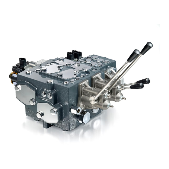
Danfoss PVG 16 Service And Parts Manual
Proportional valve group
Hide thumbs
Also See for PVG 16:
- Service manual (28 pages) ,
- Installation manual (6 pages) ,
- Technical information (112 pages)

Related Manuals for Danfoss PVG 16


Summary of Contents for Danfoss PVG 16
- Page 1 Service and Parts Manual Proportional Valve Group PVG 16/32/128/256 www.danfoss.com...
- Page 2 Service and Parts Manual PVG 16/32/128/256 Revision history Table of revisions Date Changed October 2018 Combined PVG 16/32/128/256 installation guides, service and parts manuals 0101 © Danfoss | October 2018 AX284661889190en-000101...
-
Page 3: Table Of Contents
Service and Parts Manual PVG 16/32/128/256 Contents Function Safety in Systems....................................5 PVG 16/32 sectional drawings..............................7 PVG 128/256 Sectional Drawing...............................10 Installation PVG 16 installation..................................11 Standard assembly...................................11 Plug orientation..................................12 Maximum flow setting................................13 Pressure setting and adjustment............................14 Installation of lever...................................16 Bleeding....................................... - Page 4 PVBS main spool..................................127 PVM mechanical activation..............................128 PVMD cover....................................129 PVH hydraulic actuation..............................130 PVHC high current actuation............................. 131 PVEO on/off actuator................................133 PVEH proportional actuator............................... 135 PVS end plates..................................137 PVAS stay bolts..................................139 Seal kits...................................... 140 © Danfoss | October 2018 AX284661889190en-000101...
-
Page 5: Safety In Systems
This example breaks down the control system into smaller bits explaining the architecture in depth. Even though many Danfoss components are used in the PVG control system. The function of the control system is to use the output from the PVE together other external sensors to ensure the PLUS+1 main controllers correct function of the aerial lift. - Page 6 A mix of electrical actuation and hydraulic actuation on the same valve stack is not safe. PVE and PVH are designed for different pilot pressure. Cost-free repairs, as mentioned in Danfoss General Conditions of Sale, are carried out only at Danfoss or at service shops authorized by Danfoss.
-
Page 7: Pvg 16/32 Sectional Drawings
Service and Parts Manual PVG 16/32/128/256 Function PVG 16/32 sectional drawings Sectional views of the product help identify certain components for servicing. PVG 16/32 PVP open center PVG 16/32 closed center © Danfoss | October 2018 AX284661889190en-000101 | 7... - Page 8 Service and Parts Manual PVG 16/32/128/256 Function PVG 16 with PVEO PVG 16 with PVEA © Danfoss | October 2018 AX284661889190en-000101...
- Page 9 Service and Parts Manual PVG 16/32/128/256 Function PVG 32 with PVEO PVG 32 with PVEH © Danfoss | October 2018 AX284661889190en-000101 | 9...
-
Page 10: Pvg 128/256 Sectional Drawing
Service and Parts Manual PVG 16/32/128/256 Function PVG 128/256 Sectional Drawing PVG 256 with PVEH PVG 256 with PVEO 10 | © Danfoss | October 2018 AX284661889190en-000101... -
Page 11: Installation
Service and Parts Manual PVG 16/32/128/256 Installation PVG 16 installation Standard assembled PVG 16 The exploded view illustration helps identify PVG 16 components to assist in installation. Oil flow direction for standard assembled PVG 16 PVEO/A PVB16 PVEA-F PVEO/A-CI PVHC... -
Page 12: Plug Orientation
Service and Parts Manual PVG 16/32/128/256 Installation PVG 16 Plug orientation The plug/port orientation shows dimensions of assembled product based on number of PVB used and data on mounting threads. Mounting thread: Mounting thread: M8 x min 10 mm or... -
Page 13: Maximum Flow Setting
Service and Parts Manual PVG 16/32/128/256 Installation PVG 16/32 pump side module, PVP Pump side and max flow setting Flow P Max. flow: P 6±1Nm[53±9lbf-in] © Danfoss | October 2018 AX284661889190en-000101 | 13... -
Page 14: Pressure Setting And Adjustment
Service and Parts Manual PVG 16/32/128/256 Installation PVG 16 pressure setting, PVP/PVB PVG 16 pressure setting (LS connection) LS B Relief valve adjustment 4[0.16] 360° ≈ 120bar [1740 psi] The table below determines which availability of relief valve based on date of PVP/PVB purchase. - Page 15 Service and Parts Manual PVG 16/32/128/256 Installation Rated pressure Product Rated pressure PVG 16 with PVS 300 bar [4351 psi] PVG 16 with PVSI 350 bar [5076 psi] Torque on connection/port based on seal used Max. tightening torque Connection/port LS, M, LSA,...
-
Page 16: Installation Of Lever
Service and Parts Manual PVG 16/32/128/256 Installation PVG 16 installation of lever PVM— lever installation positions and range Standard installation is shown on the left, installation with float is shown on the right. 16 | © Danfoss | October 2018... -
Page 17: Bleeding
If the group is installed vertically, it is recommended to bleed it at the adjusting screws (Pos. A). It may be necessary to bleed the PVEK because of the hydraulic build-up of PVEA. PVG 16/32 bleeding © Danfoss | October 2018... -
Page 18: Pve Series 6
Service and Parts Manual PVG 16/32/128/256 Installation PVG 16 with PVE series 6 installation PVE series 6 exploded view 5 [0.2] 5 [0.2] 8 ± 0.5 Nm 8 ± 0.5 Nm [70 ± 4.4 lbf in] [70 ± 4.4 lbf in] When installing, protect the LVDT pin (if present), ensure O-rings are in place and be sure to not over- torque. -
Page 19: Relevant Technical Data
Maximum 460 mm /sec [2128 SUS] Oil cleanliness Minimum 18/16/13 (according to ISO 4406) PVG 16 connector variants PVG 16 connector variants for PVEO, PVEA, PVEO-CI, PVEA-CI, PVEA-F with pin layout information. © Danfoss | October 2018 AX284661889190en-000101 | 19... - Page 20 2 x 4 DEUTSCH CAN_H CAN_L Vbat Vneg Pin layout for PVEA-F Connector Pin 1 Pin 2 Pin 3 Pin 4 Pin 5 Pin 6 1 x 6 DEUTSCH Vi Vneg Vbat 20 | © Danfoss | October 2018 AX284661889190en-000101...
-
Page 21: Pvhc
Service and Parts Manual PVG 16/32/128/256 Installation PVHC for PVG 16 8 ±0.5 Nm [70 ±4.4 lbf •in] 5 [0.197] The seal in the PVHC connector and the seals for individual conductors are crucial for correctly sealing the conductor. Technical data... -
Page 22: Led Characteristics
Service and Parts Manual PVG 16/32/128/256 Installation PVG 16 LED characteristics For troubleshooting LED characteristics, please see the Technical Information document for PVG 16. PVEO LED characteristics Color LED view Function Green Power ON PVEA LED characteristics Green Operating Green @ 1.5 Hz... -
Page 23: Standard Main Spool Assembly
Service and Parts Manual PVG 16/32/128/256 Installation PVG 16 main spool assembly 8±1Nm 8±1Nm © Danfoss | October 2018 AX284661889190en-000101 | 23... -
Page 24: Pvg 32 Installation
Service and Parts Manual PVG 16/32/128/256 Installation PVG 32 installation Standard assembled PVG 32 The exploded view illustration helps identify PVG 32 components to assist in installation. Oil flow direction for standard assembled PVG 16 PVEP PVB32 PVED PVEO/A/M PVEH... -
Page 25: Plug Orientation
Number of PVB 32 1 [in] [3.23] [5.12] [7.01] [8.90] [10.79] [12.68] [14.57] [16.46] [18.35] [20.24] [22.13] [24.02] [in] [5.55] [7.48] [9.37] [11.30] [13.19] [15.12] [17.01] [18.94] [20.83] [22.76] [24.65] [26.57] © Danfoss | October 2018 AX284661889190en-000101 | 25... -
Page 26: Maximum Flow Setting
Service and Parts Manual PVG 16/32/128/256 Installation PVG 16/32 pump side module, PVP Pump side and max flow setting Flow P Max. flow: P 6±1Nm[53±9lbf-in] 26 | © Danfoss | October 2018 AX284661889190en-000101... -
Page 27: Pressure Setting And Adjustment
G1/4 With steel washer 130 N•m [1150 210 N•m [1850 130 N•m [1150 210 N•m [1850 40 N•m [350 17 N•m [150 40 N•m [350 lbf•in] lbf•in] lbf•in] lbf•in] lbf•in] lbf•in] lbf•in] © Danfoss | October 2018 AX284661889190en-000101 | 27... - Page 28 With cutting edge 130 N•m [1150 210 N•m [1850 130 N•m [1150 210 N•m [1850 40 N•m [350 17 N•m [150 40 N•m [350 lbf•in] lbf•in] lbf•in] lbf•in] lbf•in] lbf•in] lbf•in] 28 | © Danfoss | October 2018 AX284661889190en-000101...
-
Page 29: Installation Of Lever
If the group is installed vertically, it is recommended to bleed it at the adjusting screws (Pos. A). It may be necessary to bleed the PVEK because of the hydraulic build-up of PVEA. PVG 16/32 bleeding © Danfoss | October 2018... -
Page 30: Pvep Series 4
No connection Not used PVEP series 4 for PVG 32 technical data PVEP control specification Description Type Value Supply Voltage (UDC) Range 11 to 32 VDC Max. ripple Max. 5 min 36 V 30 | © Danfoss | October 2018 AX284661889190en-000101... - Page 31 4 cSt [39 SUS] Maximum 460 cSt [2128 SUS] Oil Cleanliness Maximum 18/16/13 (according to ISO 4406) PVEP LED characteristics Green Operating Internal fault Red @ 1.5 Hz External or float fault © Danfoss | October 2018 AX284661889190en-000101 | 31...
-
Page 32: Pved-Cc Series 5
Pin layout for PVEP Type Connector Pin 1 Pin 2 Pin 3 Pin 4 PVEP 2x4 AMP CAN-L Vbat+ CAN-H 2x4 DEUTSCH CAN-H CAN-L Vbat+ All pins are internally connected. Internally connected 32 | © Danfoss | October 2018 AX284661889190en-000101... - Page 33 Operating Range 12 – 75 cSt [65 – 347 SUS] Minimum 4 cSt [39 SUS] Maximum 460 cSt [2128 SUS] Oil Cleanliness Maximum 18/16/13 (according to ISO 4406) Grade of enclosure IP 66 © Danfoss | October 2018 AX284661889190en-000101 | 33...
-
Page 34: Pve Series 7
2 x 4 AMP 1 x 6 AMP 1 x 4 DIN 2418 PVEO-DI 4-pin AMP Connector Pinout Pin 1 Pin 2 Pin 3 Pin 4 2x4 AMP (A) 2x4 AMP (B) DI-B DI-A 34 | © Danfoss | October 2018 AX284661889190en-000101... - Page 35 0.04 l/min [0.01 US gal/min] Locked Position 0.04 l/min [0.01 US gal/min] Actuating 0.6 l/min [0.16 US gal/min] Storage Temperature Ambient -50 to +90°C [-58 to +194°F] Operating Temperature Ambient -40 to +90°C [-40 to +194°F] © Danfoss | October 2018 AX284661889190en-000101 | 35...
- Page 36 PVE series 7 for PVG 32 LED characteristics The LED provided on the PVE products can tell the user if the product is operating correctly or not. PVEO LED characteristics Color LED view Function Green Power ON 36 | © Danfoss | October 2018 AX284661889190en-000101...
- Page 37 Red @ 1.5 Hz External or Float fault PVEH-U/PVES-U LED characteristics Green Operating Green @ 1.5 Hz Neutral - Power Save Internal fault Red @ 1.5 Hz External or Float fault Yellow Disable Mode © Danfoss | October 2018 AX284661889190en-000101 | 37...
-
Page 38: Pvhc
20.8 Ω ± 5% Pilot pressure (over tank) Nominal 25 bar [363 psi] Minimum 21 bar [305 psi] Maximum 25 bar [363 psi] Control pressure Range 5 - 15 bar [72.5 - 217.5 psi] 38 | © Danfoss | October 2018 AX284661889190en-000101... - Page 39 23/19/16 (ISO 4406, 1999 version) Filtering in the hydraulic system; Max. permissible degree of contamination Designed to be used with hydraulic activated spools The PVHC is produced in an environment using mineral based hydraulic oil. © Danfoss | October 2018 AX284661889190en-000101 | 39...
-
Page 40: Standard Main Spool Assembly
Service and Parts Manual PVG 16/32/128/256 Installation PVG 32 main spool assembly installation Standard main spool assembly 12[0.47] DETENT 8±1Nm (NO SPRING) [71±9lbf-in] 11[0.43] 8±1Nm 8±1Nm [71±9lbf-in] [71±9lbf-in] 40 | © Danfoss | October 2018 AX284661889190en-000101... -
Page 41: Pvg 128/256 Installation
PVB256 PVEO PVHC PVMD P006 089 Identification C PVG - number, week and year of installation and series number PVP - pressure setting D Engraved part number on PVPV, PVB and PVSI © Danfoss | October 2018 AX284661889190en-000101 | 41... -
Page 42: Plug Orientation
626.5 L (in) 3.88 6.48 9.07 11.67 14.27 16.87 19.47 22.07 24.67 PVB 256 L (mm) 118.5 204.5 290.5 376.5 462.5 548.5 634.5 L (in) 4.67 8.05 11.44 14.82 18.21 21.59 24.98 42 | © Danfoss | October 2018 AX284661889190en-000101... -
Page 43: Pump Side Module
Installation PVG 128/256 pump side module Pump side and max flow setting Flow: P→A Max. flow: P→B 18 ±2 N•m [159 ±18 lbf•in] Max. flow: P→A 18 ±2 N•m [159 ±18 lbf•in] © Danfoss | October 2018 AX284661889190en-000101 | 43... -
Page 44: Pressure Setting
4 [0.16] 360º ~120 bar [1740 psi] Relief valve LS P006094 Rated pressure Product Rated Pressure PVG 128 with PVSI 350 bar [5076 psi] PVG 256 w PVSI 350 bar [5076 psi] 44 | © Danfoss | October 2018 AX284661889190en-000101... -
Page 45: Installation Of Lever
Service and Parts Manual PVG 16/32/128/256 Installation PVG 128/256 installation of lever The lever must be screwed in completely. PVM lever PVM Standard PVM with float © Danfoss | October 2018 AX284661889190en-000101 | 45... -
Page 46: Pve Series 7
Error PVEH-FLA 1x6 DEUTSCH Error Float PVG 128/256 PVE control specifications PVEO control specifications Control specification PVEO Supply Voltage (Udc) Rated 12 Vdc 24 Vdc Range 11→15 Vdc 22→30 Vdc Max. ripple 46 | © Danfoss | October 2018 AX284661889190en-000101... - Page 47 Green @ 1.5 Hz Neutral - Power Save Internal fault Red @ 1.5 Hz External or Float fault PVEH-U LED characteristics Color LED view Funtion Green Operating Green @ 1.5 Hz Neutral - Power Save © Danfoss | October 2018 AX284661889190en-000101 | 47...
- Page 48 Service and Parts Manual PVG 16/32/128/256 Installation PVEH-U LED characteristics (continued) Color LED view Funtion Internal fault Red @ 1.5 Hz External or Float fault Yellow Disable mode 48 | © Danfoss | October 2018 AX284661889190en-000101...
-
Page 49: Pvhc
-30°C → 80°C [-22°F → 176°F] Medium -20°C → 80°C [-4°F → 176°F] Oil viscosity Operating range 12 → 75 mm2/s [65 → 347 SUS] Minimum 4 mm /s [39 SUS] Maximum 400 mm /s [2130 SUS] © Danfoss | October 2018 AX284661889190en-000101 | 49... - Page 50 DEUTSCH DT IP 67 AMP JPT 12/24 V IP 66 23/19/16 (ISO 4406, 1999 version) Filtering in the hydraulic system; Max. permissible degree of contamination Designed to be used with hydraulic activated spools 50 | © Danfoss | October 2018 AX284661889190en-000101...
-
Page 51: Standard Main Spool Assembly
PVG 16/32/128/256 Installation PVG 128/256 main spool assembly installation Standard spools for PVE and PVH/PVHC Spool for PVE Spool for PVH/PVHC 16±2Nm [141±18lbf-in] 16±2Nm [141±18lbf-in] Same tightening torque for PVE and PVH/PVHC spools © Danfoss | October 2018 AX284661889190en-000101 | 51... -
Page 52: Service Parts
Closed Center PVP with Priority PVPX, LS LS Unloading valve End Plate (Aluminum) PVSI End Plate (Cast Iron) PVSKM Full Flow Cut-Off Module PVSP/PVSPM Priority Module Tank Side Module PVTI Interface Module 52 | © Danfoss | October 2018 AX284661889190en-000101... -
Page 53: Pvg 16 Service Parts
Service and Parts Manual PVG 16/32/128/256 Service Parts PVG 16 service parts PVG 16 pump side module PVP PVP exploded view 6[0.24] 30±3Nm [266±27lbf-in] 5±0.5Nm [44±4.4lbf-in] 5±0.5Nm [44±4.4lbf-in] 4[0.16] 8±1Nm [71±9lbf-in] 5±0.5Nm [44±4.4lbf-in] 2.5[1.0] 4±1Nm [35±9lbf-in] 6[0.24] 6[0.24] 30±3Nm [266±27lbf-in] 30±3Nm... - Page 54 Plastic plug for G3/4” Plastic plug for 1-1/16-12 UNF - N/A (See PVP for PVG32) Conversion kit open to closed 155L5152 and closed to open center Orifice Ø1.0, bonded seal and plug for closed center 54 | © Danfoss | October 2018 AX284661889190en-000101...
- Page 55 Item Description Code Letter number Plug M6 for open center 155L5153 Plug with O-ring N/A (See PVP for PVG32) Inlet compensator assembly Plastic plug Locking pin Orifice M6 Ø1.0 PVP inlet module © Danfoss | October 2018 AX284661889190en-000101 | 55...
-
Page 56: Pump Side Module Pvpv
Service and Parts Manual PVG 16/32/128/256 Service Parts PVG 16 pump side module PVPV PVPV exploded view 5±0.5Nm [44±4.4lbf-in] 6[0.24] 30±3Nm [266±27lbf-in] 6[0.24] 30±3Nm [266±27lbf-in] 13[0.51] 35±3Nm [310±27lbf-in] 6[0.24] 30±3Nm [266±27lbf-in] PVPV kits Description Code number P-port T-port Letter Closed center with PPRV for PVH/PVHC... -
Page 57: Electrical Ls Pressure Unloading Valve, Pvpx
Service and Parts Manual PVG 16/32/128/256 Service Parts PVG 16/32 electrical LS pressure unloading valve, PVPX PVPX exploded view 24[0.94] 45+5Nm [398+44lbf-in] 24[0.94] 45+5Nm [398+44lbf-in] 24[0.94] 45+5Nm [398+44lbf-in] 24[0.94] 45+5Nm [398+44lbf-in] PVPX plug Description Manual Override Item Code number Plug for PVPX port... - Page 58 1x2 DIN (24 Vdc) PUSH 157B4258 1x2 DIN (24 Vdc) PUSH & TURN 157B4259 1x2 DIN (26 Vdc) PUSH 157B4260 1x2 AMP (12 Vdc) PUSH 157B4985 1x2 AMP (24 Vdc) PUSH 157B4986 58 | © Danfoss | October 2018 AX284661889190en-000101...
-
Page 59: Pvb With Ls Port
Service and Parts Manual PVG 16/32/128/256 Service Parts PVG 16 PVB with LS, basic module PVB with LS exploded view 6[0.24] 30±3Nm [266±27lbf-in] PVB with LS kits Description Code number A-port B-port Letter Compensated PVB 11130976 3/8” BSP 3/8” BSP 11130977 3/4”-16 UNF... - Page 60 Code number Letter Sealed adjusting screw (for sealing with a wire) 155L6489 Sealed plastic plug, black (50 pcs.) 155L6168 Sealed plastic plug, yellow (50 pcs.) 155L6167 Shuttle disc assembly Compensator assembly Locking pin 60 | © Danfoss | October 2018 AX284661889190en-000101...
-
Page 61: Pvb With Pvlp/Pvla, Basic Module
Service and Parts Manual PVG 16/32/128/256 Service Parts PVG 16 PVB with PVLP/PVLA, basic module PVB with PVLP/PVLA exploded view 13[0.51] 35±3Nm 13[0.51] [310±27lbf-in] 35±3Nm [310±27lbf-in] 6[0.24] 30±3Nm [266±27lbf-in] PVB with PVLP/PVLA kits Description Code number A-port B-port Letter Compensated PVB 11130976 3/8”... - Page 62 3/4”-16 UNF PVB with PVLP/PVLA parts list Item Description Code number Letter PVB basic module PVLA See PVLP/PVLA PVLP See PVLP/PVLA Plug for PVLP/PVLA 157B2002 Shuttle disc assembly Compensator assembly Locking pin 62 | © Danfoss | October 2018 AX284661889190en-000101...
-
Page 63: Pvlp Shock And Pvla, Suction Valves
Part number PVLP/PVLA PVLA 157B2001 PVLP 157B2032 157B2050 157B2063 157B2080 157B2100 157B2125 157B2140 157B2150 157B2160 157B2175 157B2190 157B2210 157B2230 157B2240 157B2250 157B2265 157B2280 Part number: 157B2230 157B2300 157B2320 157B2350 157B2380 Plug 157B2002 © Danfoss | October 2018 AX284661889190en-000101 | 63... -
Page 64: Pvbs, Main Spool
Closed neutral, use with PVE 11109642 11109643 11109644 11109645 11109646 11109647 Closed neutral, use with PVH 11146752 11146753 11146754 11146755 11146756 11146757 For more PVG 16 PVBS part numbers, please see PVG 16 Technical Information. 64 | © Danfoss | October 2018 AX284661889190en-000101... -
Page 65: Pvm Mechanical Activation
Service and Parts Manual PVG 16/32/128/256 Service Parts PVG 16 PVM mechanical activation PVM exploded view 10[0.40] 6±1Nm [53±9lbf-in] 3[0.12] 4[0.12] 2.5±1Nm [22±9lbf-in] 5[0.20] 8±0.5Nm [70±4.5lbf-in] 13[0.51] 8±1Nm [70±9lbf-in] PVM kits Description Code number Letter Non-adjustable 11107505 Non-adjustable with float... -
Page 66: Pvmd Cover
Service and Parts Manual PVG 16/32/128/256 Service Parts PVG 16 PVMD cover PVMD exploded view 5 [0.2] 8 ± 0.5 Nm [70 ± 4.4 lbf in] PVMD kit Description Code number Cover for mechanical activation 11105518 PVMD parts list Item Description Screw M6x15 (4 pcs.) -
Page 67: Pvh Hydraulic Actuation
Service and Parts Manual PVG 16/32/128/256 Service Parts PVG 16 PVH hydraulic actuation PVH exploded view 5 [0.2] 8 ± 0.5 Nm [70 ± 4.4 lbf in] PVH kits Description Code number G1/4” BSP 11108380 9/16-18 UNF 11108381 Item Description Screw M6x15 (4 pcs.) -
Page 68: Pvhc High Current Actuation
Service and Parts Manual PVG 16/32/128/256 Service Parts PVG 16 PVHC high current actuation PVHC exploded view 5 [0.2] 8 ± 0.5 Nm [70 ± 4.4 lbf in] 4 [0.16] 3 Nm [26.5 lbf in] PVHC kits Description Code number... -
Page 69: Pve Series 6 Pveo On/Off Actuator
Service and Parts Manual PVG 16/32/128/256 Service Parts PVG 16 PVE S6 PVEO on/off actuator PVEO 5 [0.2] 8 ± 0.5 Nm [70 ± 4.4 lbf in] PVEO kits Type Description Code number PVEO 1x4 DEUTSCH (12 Vdc) 11106793 1x4 DEUTSCH (24 Vdc) -
Page 70: Pve Series 6 Pvea Proportional Actuator
Service and Parts Manual PVG 16/32/128/256 Service Parts PVG 16 PVE S6 PVEA, proportional actuator PVEA 5 [0.2] 8 ± 0.5 Nm [70 ± 4.4 lbf in] Type Description Code number PVEA 1x4 DEUTSCH 11103692 PVEA-F 1x4 DEUTSCH (Float B-port) -
Page 71: Pvs/Pvsi End Plates
Service and Parts Manual PVG 16/32/128/256 Service Parts PVG 16/32 PVS/PVSI end plates PVS/PVSI exploded view 5±0.5Nm [44±4.4lbf-in] PVSI with P, T, LX, and M connection exploded view 4±0.5Nm [35±4.4lbf-in] 5±0.5Nm [44±4.4lbf-in] 4±0.5Nm [35±4.4lbf-in] PVST with T connection exploded view 5±0.5Nm... - Page 72 Description Code Letter number PVS/PVSI End plate with LX-connection Plastic plug PVSI with P-, T-, LX- and M-connection Plastic plug Plastic plug Plastic plug PVST with T-connection Plastic plug Plug with O-ring 72 | © Danfoss | October 2018 AX284661889190en-000101...
-
Page 73: Pvas Stay Bolts
Service and Parts Manual PVG 16/32/128/256 Service Parts PVG 16/32 PVAS stay bolts PVAS exploded view Item Description Code number Set of seals for 7 work sections: PVB 16/32 11156335 For PVAS part numbers, refer to the relevant Technical Information document. -
Page 74: Seal Kits
Module 157B6999 PVM/PVH/PVMD Module 157B3999 PVEO/PVEA/PVEO-CI/PVEA-CI/PVHC Module 11133165 Seal kit for one work section For a PVG 16 with 1 PVB-section 157B8999 Seal kit for seven work sections For a PVG 16 with 7 PVB-section 11156335 PVPX Module 157B5996 PVPX... -
Page 75: Pvg 32 Service Parts
1-1/16-12 UNF 1-1/16-12 UNF Open center with PPRV for PVE and T0 11072195 M27x2.0 M27x2.0 facility and pilot oil pressure take-off 157B5130 G3/4” G3/4” 157B5330 1-1/16-12 UNF 1-1/16-12 UNF 157B5964 M22x1.5 M22x1.5 © Danfoss | October 2018 AX284661889190en-000101 | 75... - Page 76 Closed center with PPRV for PVH/PVHC and 11051802 1-1/16-12 UNF 1-1/16-12 UNF T0 facility Closed center with PPRV for PVH/PVHC and 157B5191 G3/4” G3/4” pilot oil pressure take-off 157B5391 1-1/16-12 UNF 1-1/16-12 UNF 76 | © Danfoss | October 2018 AX284661889190en-000101...
- Page 77 Orifice Ø1.0, bonded seal and plug for closed center M6 plug for open center 155L5153 Plug with O-ring Plastic plug Inlet compensator assembly Plastic plug Locking pin Orifice M6 Ø1.0 PVP inlet module © Danfoss | October 2018 AX284661889190en-000101 | 77...
-
Page 78: Pump Side Module Pvpv
11124107 1-1/16-12 UNF 1-1/16-12 UNF This module includes the plug for external Pp (item 5) PVPV parts list Item Description Code number Letter PVLP assembly See PVLP section Plug for PVLP 157B2002 78 | © Danfoss | October 2018 AX284661889190en-000101... - Page 79 PVPV parts list (continued) Item Description Code number Letter Plug Pilot suplly for PVE 13.5 bar 155L5157 Pilot suplly for PVH/PVHC 25 11077272 Plug for external Pp Plastic plug Plug PVPV inlet module © Danfoss | October 2018 AX284661889190en-000101 | 79...
-
Page 80: Pump Side Module Pvpm/Pvpvm
See PVLP section Plug for PVLP 157B2002 Plug Pilot supply for PVE 13.5 bar 155L5157 Pilot supply for PVH/PVHC 25 bar 11077272 Plug for external Pp Plastic plug Plug PVPV inlet module 80 | © Danfoss | October 2018 AX284661889190en-000101... -
Page 81: Electrical Ls Pressure Unloading Valve, Pvpx
Service and Parts Manual PVG 16/32/128/256 Service Parts PVG 16/32 electrical LS pressure unloading valve, PVPX PVPX exploded view 24[0.94] 45+5Nm [398+44lbf-in] 24[0.94] 45+5Nm [398+44lbf-in] 24[0.94] 45+5Nm [398+44lbf-in] 24[0.94] 45+5Nm [398+44lbf-in] PVPX plug Description Manual Override Item Code number Plug for PVPX port... - Page 82 1x2 DIN (24 Vdc) PUSH 157B4258 1x2 DIN (24 Vdc) PUSH & TURN 157B4259 1x2 DIN (26 Vdc) PUSH 157B4260 1x2 AMP (12 Vdc) PUSH 157B4985 1x2 AMP (24 Vdc) PUSH 157B4986 82 | © Danfoss | October 2018 AX284661889190en-000101...
-
Page 83: External Pilot Pressure Adapter, Pvpc
PVG 32 external pilot pressure adapter, PVPC PVPC exploded view 198[0.75] 40±3Nm [355±25lbf-in] Type Item Thread Code number PVPC without check valve G1/2” 157B5400 1/2-20 UNF 158X1000 PVPC with check valve G1/2” 157B5600 1/2-20 UNF 157B5700 © Danfoss | October 2018 AX284661889190en-000101 | 83... -
Page 84: Pvb Basic Module
157B6400 7/8-14 UNF Basic module with T0 157B6010 G1/2” 157B6410 7/8-14 UNF Basic module with PVLP/PVLA 157B6030 G1/2” 157B6430 7/8-14 UNF Basic module with PVLP/PVLA and 11071832 G1/2” LS A/B shuttle valve 84 | © Danfoss | October 2018 AX284661889190en-000101... - Page 85 Basic module with T0 11059838 G1/2” G1/4” 11126963 7/8-14 UNF 1/2-20 UNF Basic module with PVLP/PVLA 157B6854 G1/2” G1/4” 11127277 7/8-14 UNF 1/2-20 UNF Basic module with PVLP/PVLA and 11126964 7/8-14 UNF 1/2-20 UNF © Danfoss | October 2018 AX284661889190en-000101 | 85...
- Page 86 Sealed plastic plug, yellow (50 155L6167 pcs.) Relief valve 155L6495 Compensator assembly Plug Damping screw Load drop check valve assembly LS shuttle valve assembly Shuttle disc Plastic plug PVB basic module 86 | © Danfoss | October 2018 AX284661889190en-000101...
-
Page 87: Basic Module, Pvbz
157B6662 7/8-14 UNF A/B-port Basic module with thermo relief and 157B6266 G1/2” A/B-port LS A/B shuttle valve 157B6666 7/8-14 UNF A/B-port 157B6954 m22x1.5 A/B-port 157B6952 Machined top A/B-port 157B6958 Machined top A/B-port © Danfoss | October 2018 AX284661889190en-000101 | 87... - Page 88 Description Code number Letter Plastic plug Thermo relief valve Pilot valve Shuttle disc Pilot operated check valve (POC) Compensator assembly Plug Locking pin LS shuttle valve assembly Pilot operated check valve (POC) 88 | © Danfoss | October 2018 AX284661889190en-000101...
-
Page 89: Pvbz With Pvbd Diverter
PVBD diverter 6/2 shift valve 157B1501 M22 x 1.5 157B1503 7/8-14 UNF Multi-valve for PVBZ 11027604 M22 x 1.5 Item Description Code number Letter PVBD Diverter Plastic plugs Screw PVBD spool PVC assembly PVC Solenoid © Danfoss | October 2018 AX284661889190en-000101 | 89... - Page 90 Code number Letter Pilot operated check valve (POC) LS shuttle valve assembly Locking pin Plug Compensator assembly Pilot operated check valve (POC) Shuttle disc Pilot valve PVBZ basic module with manifold interface 90 | © Danfoss | October 2018 AX284661889190en-000101...
-
Page 91: Pvlp Shock And Pvla, Suction Valves
Part number PVLP/PVLA PVLA 157B2001 PVLP 157B2032 157B2050 157B2063 157B2080 157B2100 157B2125 157B2140 157B2150 157B2160 157B2175 157B2190 157B2210 157B2230 157B2240 157B2250 157B2265 157B2280 Part number: 157B2230 157B2300 157B2320 157B2350 157B2380 Plug 157B2002 © Danfoss | October 2018 AX284661889190en-000101 | 91... -
Page 92: Pvbs Main Spool
PVG 16/32/128/256 Service Parts PVG 32 PVBS main spool PVBS exploded view 12[0.47] 8±1Nm [71±9lbf-in] DETENT (NO SPRING) 11[0.43] 8±1Nm [71±9lbf-in] 8±1Nm [71±9lbf-in] For spool part numbers, see PVG 32 Technical Information. 92 | © Danfoss | October 2018 AX284661889190en-000101... -
Page 93: Pvm Medchanical Activation
Code number Letter Seal kit 157B3999 Lever base 11064641 Lever with black knob 11077262 Lever base and lever with black 11107587 knob Lever base and lever with red knob 11134809 Screw M6x15 © Danfoss | October 2018 AX284661889190en-000101 | 93... -
Page 94: Pvmd, Pvmr And Pvmf Covers
Cover in aluminum 157B0001 Cover in anodized aluminum 157B0009 Cover in cast iron 157B0021 PVMF Cover in aluminum 157B0005 PVMR Cover in aluminum 157B0004 Cover in anodized aluminum 157B0012 Cover in cast iron 157B0024 94 | © Danfoss | October 2018 AX284661889190en-000101... - Page 95 Service and Parts Manual PVG 16/32/128/256 Service Parts Parts list Item Description Code number Letter Screw Seal kit 157B3999 Friction detent plug assembly Screw Seal kit 157B3999 © Danfoss | October 2018 AX284661889190en-000101 | 95...
-
Page 96: Pvh Hydraulic Actuation
Description Connection Code number Aluminum 9/16-18 UNF 157B0007 Anodized aluminum 157B0010 Cast iron 157B0014 Aluminum G1/4” 157B0008 Anodized aluminum 157B0011 Cast iron 157B0016 Item Description Code number Amount Screw Seal kit 157B3999 96 | © Danfoss | October 2018 AX284661889190en-000101... -
Page 97: Electrical Actuation Pvhc
11112037 AMP connector - 24 V 11112036 DEUTSCH connector – 12 V 11112038 DEUTSCH connector – 24 V 11112039 Parts list Item Description Code number Amount Screw Solenoid valve Seal kit 157B3999 © Danfoss | October 2018 AX284661889190en-000101 | 97... -
Page 98: Pvdi Directional Indication
Directional indicator with two NO switches - 1x4 DIN 157B0105 PVDI-H (For PVH) Directional Indicator for hydraulic actuation – 1x4 DIN 157B0104 Parts list Item Description Code number Amount Screw Seal kit 157B0199 98 | © Danfoss | October 2018 AX284661889190en-000101... -
Page 99: Pvs/Pvsi End Plates
Service and Parts Manual PVG 16/32/128/256 Service Parts PVG 16/32 PVS/PVSI end plates PVS/PVSI exploded view 5±0.5Nm [44±4.4lbf-in] PVSI with P, T, LX, and M connection exploded view 4±0.5Nm [35±4.4lbf-in] 5±0.5Nm [44±4.4lbf-in] 4±0.5Nm [35±4.4lbf-in] PVST with T connection exploded view 5±0.5Nm... - Page 100 Description Code Letter number PVS/PVSI End plate with LX-connection Plastic plug PVSI with P-, T-, LX- and M-connection Plastic plug Plastic plug Plastic plug PVST with T-connection Plastic plug Plug with O-ring 100 | © Danfoss | October 2018 AX284661889190en-000101...
-
Page 101: Pvsi, Pvsd, Pvst End Plates
4±0.5Nm 30±3Nm [35±4.4lbf-in] [266±27lbf-in] PVSD end plate exploded view 35±5Nm [309±44lbf-in] 5±0.5Nm [44±4.4lbf-in] 4±0.5Nm [35±4.4lbf-in] 90±5Nm [797±44lbf-in] 6[0.24] 30±3Nm [266±27lbf-in] PVSI with PVE PPRV exploded view 6[0.24] 30±3Nm [266±27lbf-in] 6[0.24] 30±3Nm [266±27lbf-in] © Danfoss | October 2018 AX284661889190en-000101 | 101... - Page 102 Plug with O-ring Plug Pilot supply for PVE 13.5 bar Plastic plug PVSI Start plate Pilot cartridge Plastic plug Check valve Plug Plastic plug PVSD end plate PVSI with PVE PPRV Plug 102 | © Danfoss | October 2018 AX284661889190en-000101...
- Page 103 Letter Pilot supply for PVE 13.5 bar PVST with PVE PPRV and PP dump Plug Plug PVPP Electrical Pilot Shut-Off valve Plug Selector for LX Plug Pilot supply for PVE 13.5 bar © Danfoss | October 2018 AX284661889190en-000101 | 103...
-
Page 104: Pvas Stay Bolts
Service and Parts Manual PVG 16/32/128/256 Service Parts PVG 16/32 PVAS stay bolts PVAS exploded view Item Description Code number Set of seals for 7 work sections: PVB 16/32 11156335 For PVAS part numbers, refer to the relevant Technical Information document. -
Page 105: Seal Kits
For a PVG 32 with 7 PVB section 11156335 PVPX Module 157B5996 PVHC Module 11061235 PVEO/PVEM/PVEH Module before middle 1993 157B4999 PVPX Module before 1996 157B4998 PVBZ PVBZ with POC 157B6989 PVSP Priority module 157B5999 © Danfoss | October 2018 AX284661889190en-000101 | 105... -
Page 106: Pve Series 4 Pveo
157B4217 1x4 DIN – 24 V 157B4229 PVEO-DI 1x4 AMP – 12 V 11157283 1x4 AMP – 24 V 11157282 PVEO parts list Item Description Code number Amount Screw Seal kit 157B3999 106 | © Danfoss | October 2018 AX284661889190en-000101... -
Page 107: Pve Series 4 Pvea
2x4 DEUTSCH – active 157B4796 2x4 AMP – active 157B4736 2x4 AMP – passive 157B4737 PVEA-NP 1x6 DEUTSCH - active 11105542 PVEA parts list Item Description Code number Amount Screw Seal kit 157B3999 © Danfoss | October 2018 AX284661889190en-000101 | 107... -
Page 108: Pve Series 4 Pvem
1x4 DIN – 12 V 157B4416 1x4 DIN – 24 V 157B4428 PVEM-R 1x4 DIN – 12 V 157B4516 1x4 DIN – 24 V 157B4528 Item Description Code number Amount Screw Seal kit 157B3999 108 | © Danfoss | October 2018 AX284661889190en-000101... -
Page 109: Pve Series 4 Pvep
5 [0.2] 8 ± 0.5 Nm [70 ± 4.4 lbf in] PVEP kit Description Code number 1x6 DEUTSCH - active 11034832 PVEP parts list Item Description Code number Amount Screw Seal kit 157B3999 © Danfoss | October 2018 AX284661889190en-000101 | 109... -
Page 110: Pve Series 4 Pveu
1x4 DEUTSCH - passive 11089090 1x4 AMP - active 11089091 1x4 AMP – active 157B4044 1x4 AMP – passive 157B4045 PVEU parts list Item Description Code number Amount Screw Seal kit 157B3999 110 | © Danfoss | October 2018 AX284661889190en-000101... -
Page 111: Pve Series 4 Pveh
157B4332 PVEH-DI 2x4 DEUTSCH – active 157B4096 2x4 AMP - active 157B4036 2x4 AMP - passive 157B4037 PVEH-NP 1x6 DEUTSCH - active 11105543 Item Description Code number Amount Screw Seal kit 157B3999 © Danfoss | October 2018 AX284661889190en-000101 | 111... -
Page 112: Pve Series 4 Pves
1x4 AMP – passive (anodized) 157B4865 1x4 DIN – active 157B4832 1x4 DIN – passive 157B4833 PVES-SP 1x6 DEUTSCH - passive 11108994 PVES parts list Item Description Code number Amount Screw Seal kit 157B3999 112 | © Danfoss | October 2018 AX284661889190en-000101... -
Page 113: Pved-Cc Series 5
157B4987 0.175 m loop cable 11095581 CAN bus terminator with gray connector 11163647 CAN bus terminator with black connector 157B4988 PVED-CC parts list Item Description Code number Amount Screw Seal kit 157B3999 © Danfoss | October 2018 AX284661889190en-000101 | 113... -
Page 114: Pve Series 7 Pveo
1x4 DIN - 12 V 11166831 1x4 DIN - 24 V 11166908 PVEO-DI 2x4 AMP – 12 V 11168740 2x4 AMP – 24 V 11166869 Item Description Code number Amount Screw Seal kit 157B3999 114 | © Danfoss | October 2018 AX284661889190en-000101... -
Page 115: Pve Series 7 Pveo-Hp
1x4 AMP - 12 V 11166763 1x4 AMP - 24 V 11187524 1x4 DIN - 12 V 11187551 1x4 DIN - 24 V 11187562 Parts list Item Description Code number Amount Screw Seal kit 157B3999 © Danfoss | October 2018 AX284661889190en-000101 | 115... -
Page 116: Pve Series 7 Pvem
1x4 DIN – passive 11166829 PVEM-FLB 1x4 DIN – passive 11166852 PVEM-R 1x4 DIN – passive 11166845 PVEM-Q 1x4 DIN – passive 11166853 Parts list Item Description Code number Amount Screw Seal kit 157B3999 116 | © Danfoss | October 2018 AX284661889190en-000101... -
Page 117: Pve Series 7 Pvea
1x6 DEUTSCH – active 11177345 PVEA-DI 2x4 DEUTSCH – passive 11177357 2x4 AMP – active 11177356 2x4 AMP – passive 11177355 Parts list Item Description Code number Amount Screw Seal kit 157B3999 © Danfoss | October 2018 AX284661889190en-000101 | 117... -
Page 118: Pve Series 7 Pveh
1x6 DEUTSCH – fast active 11166750 PVEH-DI 2x4 DEUTSCH – active 11166835 2x4 AMP – passive 11166820 2x4 AMP – active 11166819 Parts list Item Description Code number Amount Screw Seal kit 157B3999 118 | © Danfoss | October 2018 AX284661889190en-000101... -
Page 119: Pve Series 7 Pves
1x4 DIN – active 11166857 PVES-U 1x4 DEUTSCH – passive 11166745 1x4 AMP – active 11166747 PVES-SP 1x6 DEUTSCH - passive 11166752 Parts list Item Description Code number Amount Screw Seal kit 157B3999 © Danfoss | October 2018 AX284661889190en-000101 | 119... -
Page 120: Pvg 128/256 Service Parts
G1-1/2" BSP 11178098 SAE flange 11178117 Thread ports 1-7/8 UNF 11178119 Parts list Item Description Code numbers Letter Pilot pressure reducing valve PVPP 12V 11160318 PVPP 24V 11160319 120 | © Danfoss | October 2018 AX284661889190en-000101... - Page 121 Service and Parts Manual PVG 16/32/128/256 Service Parts Parts list (continued) Item Description Code numbers Letter Plug if no PVPP is mounted Shock and anti-cavitation Valve PVLP/PVLA © Danfoss | October 2018 AX284661889190en-000101 | 121...
-
Page 122: Pvb 128, Basic Module
Thread ports 1-7/8 UNF 11176917 Compensated basic module with LSA/B relief valve for each work port and Metric flange 11165621 2xPVLPs for each work port G1-1/2" BSP 11170527 SAE flange 11170523 Thread ports 1-7/8 UNF 11170525 122 | © Danfoss | October 2018 AX284661889190en-000101... - Page 123 Service and Parts Manual PVG 16/32/128/256 Service Parts Parts list Item Description Code number Letter 1 and 2 Shock and anti-cavitation Valve PVLP/PVLA LS relief valve 155L6495 LS relief valve service tool 155L6494 © Danfoss | October 2018 AX284661889190en-000101 | 123...
-
Page 124: Pvb 256, Basic Module
Turbo compensator feature basic module with LS A/B relief valve for each Metric flange 11183379 work port and 3xPVLPs for each work port G1-1/2" BSP 11183406 SAE flange 11183404 Thread ports 1-7/8 UNF 11183402 124 | © Danfoss | October 2018 AX284661889190en-000101... - Page 125 Service and Parts Manual PVG 16/32/128/256 Service Parts Item Description Code number Letter 1 and 2 Shock and anti-cavitation Valve PVLP/PVLA LS relief valve 155L6495 LS relief valve service tool 155L6494 © Danfoss | October 2018 AX284661889190en-000101 | 125...
-
Page 126: Pvlp Shock And Pvla, Suction Valves
Part number PVLP/PVLA PVLA 157B2001 PVLP 157B2032 157B2050 157B2063 157B2080 157B2100 157B2125 157B2140 157B2150 157B2160 157B2175 157B2190 157B2210 157B2230 157B2240 157B2250 157B2265 157B2280 Part number: 157B2230 157B2300 157B2320 157B2350 157B2380 Plug 157B2002 126 | © Danfoss | October 2018 AX284661889190en-000101... -
Page 127: Pvbs Main Spool
16±2Nm [141±18lbf-in] 16±2Nm [141±18lbf-in] Do not use hole in tension bar for tightening spool assembly. Use a 17 mm wrench instead. For spool part numbers, see PVG 128/256 Technical Information, pages 42-57. © Danfoss | October 2018 AX284661889190en-000101 | 127... -
Page 128: Pvm Mechanical Activation
Non-adjustable with base and lever 11176644 Adjustable with base and lever and BSP gauge plug 11175317 Adjustable with base and lever and BSP gauge plug 11176635 Parts list Item Description Amount O-ring 128 | © Danfoss | October 2018 AX284661889190en-000101... -
Page 129: Pvmd Cover
Parts list Item Description Code number Amount Assembly Screw kit PVMD cover, including 2 and 4 157B0001 Seal kit 157B3999 Screw kit Interface block - inverted Seal kit for 10 pcs 11191632 © Danfoss | October 2018 AX284661889190en-000101 | 129... -
Page 130: Pvh Hydraulic Actuation
9/16"-18 UNF 11187776 Parts kits Item Description Code number Amount Assembly Screw kit PVH cover, including 2 and 4 157B0008 Seal kit 157B3999 Screw kit Interface block - inverted Seal kit 11191632 130 | © Danfoss | October 2018 AX284661889190en-000101... -
Page 131: Pvhc High Current Actuation
[70±4.5 lbf·in] 5[0.20] E103 671 PVHC with DEUTSCH connector 8±0.5 Nm [70±4.5 lbf·in] 5[0.20] 8±0.5 Nm [70±4.5 lbf·in] 5[0.20] E103 677 PVHC kits Description Code number 12V AMP 11187757 12V DEUTSCH 11187772 © Danfoss | October 2018 AX284661889190en-000101 | 131... - Page 132 Code number 24V AMP 11187774 24V DEUTSCH 11187775 Parts list Item Description Code number Amount Assembly Screw kit 155L4199 Actuator assembly Seal kit 11061235 Screw kit Interface block - inverted Seal kit 11191632 132 | © Danfoss | October 2018 AX284661889190en-000101...
-
Page 133: Pveo On/Off Actuator
8±0.5 Nm [70±4.5 lbf·in] 5[0.20] E103 673 PVEO kits Description Code number 1x4 DEUTSCH (12 Vdc) 11186328 1x4 DEUTSCH (24 Vdc) 11186330 1x4 DIN (12 Vdc) 11186331 1x4 DIN (24 Vdc) 11186342 © Danfoss | October 2018 AX284661889190en-000101 | 133... - Page 134 Service and Parts Manual PVG 16/32/128/256 Service Parts Parts list Item Description Code number Amount Assembly Screw kit 155L4199 Actuator assembly Seal kit 157B4997 Screw kit Interface block Seal kit 11191632 134 | © Danfoss | October 2018 AX284661889190en-000101...
-
Page 135: Pveh Proportional Actuator
PVEH with DEUTSCH connector 8±0.5 Nm [70±4.5 lbf·in] 5[0.20] 8±0.5 Nm [70±4.5 lbf·in] 5[0.20] E103 674 PVEH-U with DIN connector 8±0.5 Nm [70±4.5 lbf·in] 5[0.20] 8±0.5 Nm [70±4.5 lbf·in] 5[0.20] E103 675 © Danfoss | October 2018 AX284661889190en-000101 | 135... - Page 136 1x4 DIN 11186324 PVEH-FLA 1x6 DEUTSCH 11186327 Parts list Item Description Code number Assembly Screw kit 155L4199 Actuator assembly Seal kit 157B4997 Screw kit Interface block Seal kit with 10 pcs 11191632 136 | © Danfoss | October 2018 AX284661889190en-000101...
-
Page 137: Pvs End Plates
Service and Parts Manual PVG 16/32/128/256 Service Parts PVG 128/256 PVS end plates PVSI end plate P109630 PVGI interface plate P109631 PVSI with P and T port P109632 © Danfoss | October 2018 AX284661889190en-000101 | 137... - Page 138 End plate with LX BSP 11179950 End plate with LX UNF 11179949 Metric Flange 1” 11171418 Thread Ports G1" BSP 11179952 SAE Flange 1” UNC screws 11171421 Thread Ports 1-5/16 UNF 11171416 138 | © Danfoss | October 2018 AX284661889190en-000101...
-
Page 139: Pvas Stay Bolts
Description Code number Set of seals for 7 work sections: PVB 32 11156335 Seat of seals for 5 work sections: PVB 128/256 11180333 For PVAS part numbers, see PVG 128/256 Technical Information. © Danfoss | October 2018 AX284661889190en-000101 | 139... -
Page 140: Seal Kits
Module 157B3999 PVEO/PVEH/PVEH-U/PVEH-FLA Seal kit for PVE 157B4997 PVEO/PVEH/PVEH-U/PVEH-FLA/PVH/PVHC Seal kit for actuator interface 11191632 Seal kit for five work sections For a PVG 128/256 with 7 PVB-section 11156335 PVHC Module 11061235 140 | © Danfoss | October 2018 AX284661889190en-000101... - Page 141 Service and Parts Manual PVG 16/32/128/256 © Danfoss | October 2018 AX284661889190en-000101 | 141...
- Page 142 Service and Parts Manual PVG 16/32/128/256 142 | © Danfoss | October 2018 AX284661889190en-000101...
- Page 143 Service and Parts Manual PVG 16/32/128/256 © Danfoss | October 2018 AX284661889190en-000101 | 143...
- Page 144 Phone: +86 21 3418 5200 Danfoss can accept no responsibility for possible errors in catalogues, brochures and other printed material. Danfoss reserves the right to alter its products without notice. This also applies to products already on order provided that such alterations can be made without subsequent changes being necessary in specifications already agreed.
Need help?
Do you have a question about the PVG 16 and is the answer not in the manual?
Questions and answers