Danfoss PVG 16 Service Manual
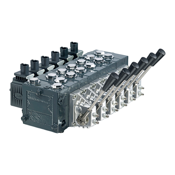
Proportional valves
Hide thumbs
Also See for PVG 16:
- Service and parts manual (144 pages) ,
- Installation manual (6 pages) ,
- Technical information (112 pages)

Subscribe to Our Youtube Channel
Related Manuals for Danfoss PVG 16


Summary of Contents for Danfoss PVG 16
- Page 1 Service Manual PVG 16 and 32 Assembly/Disassembly Guide PVG 16, PVG 32 powersolutions.danfoss.com...
- Page 2 Service Manual PVG 16 and 32 Service Assembly/Disassembly Guide Revision history Table of revisions Date Changed November 2017 Minor text change 0106 February 2017 Uodated with PVE Series 7 0105 May 2014 Testing section added, cover image Apr 2014 Converted to Danfoss layout – DITA CMS...
-
Page 3: Table Of Contents
Testing PVG 16 and 32 leak test................................22 Pressure setting after assembly..............................22 PVG 16 and 32 function testing..............................23 Recommended equipment and hand tools to assemble PVG 16 and PVG 32:..........24 Test report Order specifications L1104530 | AX00000133en-US0106 | 3 ©... -
Page 4: General Information
Service Manual PVG 16 and 32 Service Assembly/Disassembly Guide General information L1104530 | AX00000133en-US0106 © Danfoss | November 2017... -
Page 5: Pvg General Description
Service Manual PVG 16 and 32 Service Assembly/Disassembly Guide General information PVG general description PVG is a hydraulic, load-sensing proportional valve, designed for optimal machine performance and maximum design flexibility. The PVG valve design is based on a modular concept that enables machine designers to specify a valve solution suitable for multiple market segments across multiple applications. -
Page 6: Pvg Modules
Service Manual PVG 16 and 32 Service Assembly/Disassembly Guide General information PVG modules PVP, pump side modules overview • Built-in pressure relief valve • Pressure gauge connection • Versions: Open center version for systems with fixed displacement pumps ‒ Closed center version for systems with variable displacement pumps ‒... -
Page 7: Pvg 16, Pvg 32 And Open Circuit Load Sense Example
PVG 16 and 32 Service Assembly/Disassembly Guide General information PVG 16, PVG 32 and Open Circuit Load Sense Example The pump receives fluid directly from the reservoir through the inlet line. A screen in the inlet line protects the pump from large contaminants. The pump outlet feeds directional control valves such as PVG-32’s, hydraulic integrated circuits (HIC), and other types of control valves. -
Page 8: Load Sensing Controls
Service Manual PVG 16 and 32 Service Assembly/Disassembly Guide General information Load sensing controls The LS control matches system requirements for both pressure and flow in the circuit regardless of the working pressure. Used with a closed center control valve, the pump remains in low-pressure standby mode with zero flow until the valve is opened. -
Page 9: Pvbs, Main Spools With Pressure Compensated Control
Service Manual PVG 16 and 32 Service Assembly/Disassembly Guide General information PVBS, main spools with pressure compensated control The PC control maintains constant system pressure in the hydraulic circuit by varying the output flow of the pump. Used with a closed center control valve, the pump remains in high pressure standby mode at the PC setting with zero flow until the function is actuated. -
Page 10: Remote Pressure Compensated Controls
Service Manual PVG 16 and 32 Service Assembly/Disassembly Guide General information Remote pressure compensated controls The remote PC control is a two-stage control that allows multiple PC settings. Remote PC controls are commonly used in applications requiring low and high pressure PC operation. -
Page 11: Open Center Pvp
Service Manual PVG 16 and 32 Service Assembly/Disassembly Guide General information Open center PVP Description of the example: PVG 32 with open center PVP (fixed displacement pump) and PVB with flow control spool. When the pump is started and the main spools in the individual basic modules (11) are in the neutral position, oil flows from the pump, through connection P, across the pressure adjustment spool (6) to tank. - Page 12 Service Manual PVG 16 and 32 Service Assembly/Disassembly Guide Sectional view LS B LS A V310106.A 1. Pressure relief valve 11. Main spool 2. Pressure reduction valve for pilot oil supply 12. LS pressure limiting valve 3. Pressure gauge connection 13.
-
Page 13: Safety In Application
Service Manual PVG 16 and 32 Service Assembly/Disassembly Guide Safety in Application All types of control valves (incl. proportional valves) can fail, thus the necessary protection against the serious consequences of function failure should always be built into the system. For each application an assessment should be made for the consequences of pressure failure and uncontrolled or blocked movements. - Page 14 Service Manual PVG 16 and 32 Service Assembly/Disassembly Guide Safety in Application Example of a control system for man-lift using PVE Fault monitoring input signals and signals from external sensors to ensure the PLUS+1 ® main controllers correct function of the man-lift.
-
Page 15: Examples Of Wiring Block Diagram
Service Manual PVG 16 and 32 Service Assembly/Disassembly Guide Safety in Application PVG 32 – used in system with fixed displacement pumps: • PVSK, commonly used in crane application - full flow dump • PVPX, LS dump to tank PVG 100 – alternative LS dump/pilot supply disconnect: •... - Page 16 Service Manual PVG 16 and 32 Service Assembly/Disassembly Guide Safety in Application A Emergency stop / man present switch B PVE Fault monitoring signals C Neutral signal detection D Deactivation of the hydraulic system (System Control Logic, example: PLUS+1® for signal monitoring...
-
Page 17: Assembly Instructions
Assembly instructions PVG 16 and 32 general conditions The specification sheet is compiled by the sales department for assembly of a new PVG 16 and PVG 32 valve groups. 1. Before, during and after the assembly/disassembly of new PVG groups, absolute cleanliness and care must be observed with regard to internal and external parts of the units concerned. - Page 18 Assembly instructions PVG 16 and PVG 32 are symmetrical, which allows for valve groups to be “option mounted” This can be one by inserting the spools from the “B” port side and mounting the PVM’s on the “B” port side of the PVB assembly.
- Page 19 Service Manual PVG 16 and 32 Service Assembly/Disassembly Guide Assembly instructions Assembly of PVG 32 PVMR/PVMF PVMD PVEO PVEA/PVEM PVEH/PVES PVBZ Flow P w: P 6±1Nm[53±9lbf-in] w: P 6±1Nm[53±9lbf-in] P109129 8. Assemble the actuators. The manual cover PVMD or the remote hydraulic end cover must be installed with the arrow pointing upwards towards the “A/B”...
- Page 20 Service Manual PVG 16 and 32 Service Assembly/Disassembly Guide Assembly instructions For torque tighting values of the large hexagon (Y) with the detent assembly function, please see the table below. Tightening torques and widths across flats With across flats Tightening torque 8 ±0.5 N•m...
- Page 21 Service Manual PVG 16 and 32 Service Assembly/Disassembly Guide Assembly instructions 10. Issue/attach label with PVG code no. for the valve assembly. PVEH/PVES PVEA/PVEM PVEO PVMD PVMR/PVMF PVLP/PVLA PVBZ L1104530 | AX00000133en-US0106 | 21 © Danfoss | November 2017...
-
Page 22: Testing
Service Manual PVG 16 and 32 Service Assembly/Disassembly Guide Testing PVG 16 and 32 leak test After all components have been assembled and tightened to the proper specifications, a leak test with compressed air must be performed. 1. Block off all “A” and “B” ports with steel plugs. -
Page 23: Pvg 16 And 32 Function Testing
P109140 PVG 16 and 32 function testing Function testing insures the correct dynamic manual and electrical operation of the PVG 16 and PVG 32 valve assembly. This test should be performed after completing the pressure adjustments. Each section of the assembly must be tested: 1. -
Page 24: Recommended Equipment And Hand Tools To Assemble Pvg 16 And Pvg 32
25 on the next page. Sections with open ported spools will experience cylinder extension in the neutral position. Recommended equipment and hand tools to assemble PVG 16 and PVG 32: • Socket driver, Allen wrench = 2.5, 3, 4, 5, 6, 8 mm. -
Page 25: Test Report
Service Manual PVG 16 and 32 Service Assembly/Disassembly Guide Test report L1104530 | AX00000133en-US0106 | 25 © Danfoss | November 2017... -
Page 26: Order Specifications
Service Manual PVG 16 and 32 Service Assembly/Disassembly Guide Order specifications PVG 16 specification sheet L1104530 | AX00000133en-US0106 26 | © Danfoss | November 2017... - Page 27 Service Manual PVG 16 and 32 Service Assembly/Disassembly Guide Order specifications PVG 32 specification sheet L1104530 | AX00000133en-US0106 | 27 © Danfoss | November 2017...
- Page 28 Phone: +86 21 3418 5200 Danfoss can accept no responsibility for possible errors in catalogues, brochures and other printed material. Danfoss reserves the right to alter its products without notice. This also applies to products already on order provided that such alterations can be made without changes being necessary in specifications already agreed.
Need help?
Do you have a question about the PVG 16 and is the answer not in the manual?
Questions and answers