Sign In
Upload
Manuals
Brands
Comtech EF Data Manuals
Modem
SDM-300A
Comtech EF Data SDM-300A Manuals
Manuals and User Guides for Comtech EF Data SDM-300A. We have
2
Comtech EF Data SDM-300A manuals available for free PDF download: Installation And Operation Manual, Operator's Manual
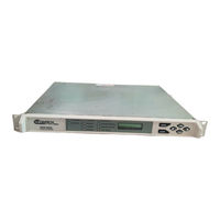
Comtech EF Data SDM-300A Installation And Operation Manual (398 pages)
Brand:
Comtech EF Data
| Category:
Modem
| Size: 5 MB
Table of Contents
Installation and Operation Manual
2
Customer Support
3
Table of Contents
4
Overview of Revisions
16
About this Manual
16
Related Documents
16
Conventions and References
17
Cautions and Warnings
17
Metric Conversion
17
Recommended Standard Designations
17
Trademarks
17
Reporting Comments or Suggestions Concerning this Manual
17
European EMC Directive
18
Warranty Policy
19
Limitations of Warranty
19
Exclusive Remedies
19
Disclaimer
19
Chapter 1. Introduction
20
Overview
21
Additional Features
22
Modes of Operation
22
Modem Construction
24
Figure 1-2. Modular Design
24
Figure 1-3. Block Diagram
25
Options
26
Table 1-1. Options
26
FAST Options
27
Table 1-2. FAST Options and Required Configurations
27
Factory Options
28
Factory- or User-Installed Options
28
Factory-Installed Options
28
UB-530 Breakout Panel
29
UB-300 Universal Breakout Panel
29
Modem Assemblies
30
Table 1-3. Efdata Part Numbers for Various Modules
30
Typical Spectral Occupancy
31
Figure 1-4. Typical Spectral Occupancy
31
Dimensional Envelope
32
Figure 1-5. Dimensional Envelope
32
Chapter 2. Installation
34
Unpacking
34
Installation
35
Figure 2-1. Installation of the Mounting Bracket
36
External Modem Connections
37
Table 2-1. Modem Rear Panel Connectors
37
Figure 2-2. Basic Modem, 25-Pin D Connector
38
Figure 2-3. (V.35) 34-Pin Winchester Connector
38
Figure 2-4. EIA-422/449, 37-Pin D Connector
38
Figure 2-5. Overhead Option, 50-Pin D Connector
38
Figure 2-6. 8-Channel, 100-Pin MUX Connector
38
Remote Connector and Pinouts (J6)
39
Table 2-2. Remote Connector and Pinouts (J6)
39
Fault Connector and Pinouts (J7)
40
Table 2-3. Fault Connector and Pinouts (J7)
40
Data I/O Interface Connector (J8)
41
Table 2-4. 25-Pin D Connector Pinouts
42
Table 2-5. 34-Pin Winchester Connector Pinouts (V.35)
43
Table 2-6. 37-Pin Connector Pinouts (Optional)
44
Table 2-7. 50-Pin Connector Pinouts
45
Data I/O Interface Connector (J8) Removal/Installation
47
Table 2-8. Connector (J8) Matrix
47
Data I/O Connector (J8) Removal
48
Data I/O Connector (J8) Installation
49
Figure 2-7. Data I/O Connector (J8) Removal/Installation
50
Auxiliary 1 Connector and Pinouts (J9)
51
Table 2-9. aux 1 Connector and Pinouts (J9)
51
Alarms Connector and Pinouts (J10)
52
RF Input Connector (CP2)
52
RF Output Connector (CP1)
52
Table 2-10. Alarms Connector and Pinouts (J10)
52
External Reference (CP3)
53
Ground Connector (GND)
53
Power Entry
53
48VDC Option
53
AC Power Connector
53
Chapter 3. Operation
54
Front Panel
54
Figure 3-1. Front Panel View
54
LED Indicators
55
Table 3-1. LED Indicators
55
Front Panel Keypad
56
Figure 3-2. Keypad
56
Menu System
58
Front Panel Menu
60
Figure 3-3. Main Menu
60
Figure 3-4. Configuration Modulator Menu
61
Configuration Modulator
62
Figure 3-5. Configuration Demodulator Menu
65
Configuration Demodulator
66
Figure 3-6. Configuration Interface Menu
69
Configuration Interface
71
Figure 3-7. Configuration Local AUPC Menu
79
Configuration Local AUPC
80
Figure 3-8. Configuration MUX
81
Configuration MUX
82
Configuration Flex Mux
85
Figure 3-10. Configuration Save Menu
87
Figure 3-11. Configuration Recall Menu
87
Configuration Recall
88
Configuration Save
88
Figure 3-12. Monitor Menu
89
Monitor
90
Figure 3-13. Faults/Alarms Menu
91
Faults/Alarms
92
Demodulator Faults
93
Modulator Faults
93
Transmit Interface Faults
93
Receive Interface Faults
94
Backward Alarms
95
Common Equipment Faults
95
Figure 3-14. Stored Faults/Alarms Menu
97
Stored Faults/Alarms
98
Unavailable Seconds Fault
98
Figure 3-15. Remote AUPC Configuration Menu
99
Figure 3-16. Remote AUPC Monitor Menu
99
Remote AUPC
100
Remote AUPC Configuration
100
Remote AUPC Monitor
100
Utility
102
Figure 3-17. Utility Modulator Menu
103
Utility Modulator
104
Figure 3-18. Utility Demodulator Menu
106
Utility Demodulator
107
Figure 3-19. Utility Interface Menu
109
Utility Interface
111
Figure 3-20. Utility System Menu
113
Utility System
115
Figure 3-21. Utility Modem Type Menu
119
Utility Modem Type Functions
121
Figure 3-22. Utility Factory Setup Menu
124
Utility Factory Setup
124
Figure 3-23. RF Loopback
125
Figure 3-24. if Loopback
125
Figure 3-25. Baseband Loopback
126
Figure 3-26. Interface Loopback
126
SDM-300A Custom Modem Defaults
127
Table 3-2. SDM-300A Custom Modem Defaults
127
Figure 3-9. Configuration Flex Mux
128
Software Configuration
129
Modem Types
129
Table 3-3. Modem Types
129
Operation
130
IDR Operation
130
Table 3-4. IDR Parameter Settings
130
IBS Operation
131
Table 3-5. IBS Parameter Settings
131
D&I Operation
132
Table 3-6. D&I Parameter Settings
132
Table 3-7. N X 64 Chart
132
ASYNC/AUPC Operation
133
Table 3-8. Asynchronous Parameter Settings
133
EFD Closed Network Operation
134
Custom Operation
135
Table 3-9. EFD Closed Network Parameter Settings
135
SDM-100 Emulation Operation
136
Table 3-10. SDM-100 Emulation Parameter Settings
136
SDM-6000 Emulation Operation
137
Table 3-11. SDM-6000 Emulation Parameter Settings
137
Revision Emulation Operation
138
Table 3-12. SDM-300A Revision Emulation
138
Clocking Options
139
EIA-232, EIA-422, or V.35 Master/Master
139
EIA-232, EIA-422, or V.35 Master/Slave
139
IDR/IBS G.703 Master/Master
140
IDR/IBS G.703 Master/Slave
140
Figure 3-27. EIA-422, EIA-232, or V.35 Master/Master Clocking Diagram
141
Figure 3-28. EIA-422, EIA-232, or V.35 Master/Slave Clocking Diagram
142
Figure 3-29. IDR/IBS G.703 Master/Master Clocking Diagram
143
Figure 3-30. IDR/IBS G.703 Master/Slave Clocking Diagram
144
Figure 3-31. D&I G.703 Master/Master Clocking Diagram
145
D&I G.703 Master/Master
146
Buffering
146
Figure 3-32. Clock Slip
147
Figure 3-33. Doppler Shift
148
Buffer Size
149
Doppler
149
Plesiochronous
150
Frame/Multiframe Length
151
Multiples of the Frame Length
151
Total Buffer Length
151
Converting between Bits and Seconds
151
Bits to Seconds
151
Seconds to Bits
151
Chapter 4. Theory of Operation
152
Monitor and Control (M&C)
152
Theory of Operation
153
Figure 4-1. M&C Block Diagram
153
Remote Baud Rate
155
Remote Address
155
Modulator
156
Figure 4-2. Modulator Block Diagram
156
Modulator Specifications
157
Theory of Operation
157
Theory of Modulation Types
158
Demodulator
159
Figure 4-3. Demodulator Block Diagram
159
Demodulator Specifications
160
Theory of Operation
160
Decoder
162
Interface
163
Figure 4-4. Interface Block Diagram
164
Interface Specifications
165
Plesiochronous/Doppler/Buffer
165
Closed Network
166
Open Network
166
Backward Alarm Theory and Connections
167
Chapter 5. Maintenance
170
System Checkout
170
Interface Checkout
171
Figure 5-1. Fault Isolation Test Setup
171
Modulator Checkout
172
Figure 5-2. Typical Output Spectrum (with Noise)
174
Figure 5-3. Typical Output Spectrum (Without Noise)
174
Demodulator Checkout
175
Figure 5-4. Typical Eye Constellations
176
Fault Isolation
177
System Faults/Alarms
177
Table 5-2. SDM-300A Fault Tree
178
Faults/Alarms Display
181
Faults/Alarms Analysis
181
Modulator Faults
182
Demodulator Faults
183
Transmit Interface Faults
184
Receive Interface Faults
185
Common Equipment Faults
187
Backward Alarms Faults
188
Appendix Aoptions
190
FAST Accessible Options
191
Table A-1. FAST Options and Required Configurations
191
A.1.1 FAST System Theory
192
A.1.2 Implementation
192
Activation Procedure
192
A.1.3 D&I
196
D&I Specifications
197
Table A-2. D&I Specifications
197
A.1.3.1 D&I Specifications
197
Figure A-1. D&I with Asynchronous Overhead Block Diagram
199
Figure A-2. D&I with Asynchronous Overhead Data Flow
200
Theory of Operation
201
A.1.3.2 Theory of Operation
201
Data Interference
201
Transmitted MUX
201
A.1.3.2.3 Receive DEMUX
202
Plesiochronous Buffer
202
Receive DEMUX
202
Backward Alarm
203
Engineering Service Channel (ESC
203
D&I Framing Formats
204
Figure A-3. E1 Framing Formats
205
Figure A-4. T1 Framing Formats
206
D&I Modem Defaults
207
Table A-3. D&I Modem Defaults
207
A.1.4 Asynchronous Interface/Aupc
208
Figure A-5. ASYNC/AUPC Block Diagram
209
A.1.4.1 Aupc
210
Aupc
210
Self-Monitoring Local Modem AUPC Control
211
A.1.4.2 Remote AUPC
212
ASYNC Data Interfaces
212
Remote AUPC
212
Terrestrial Data Interfaces
212
Theory of Operation
212
A.1.4.3.3 MUX Operation
213
Buffer Operation
213
DEMUX Operation
213
MUX Operation
213
Baseband Loopback Operation
214
Loop Timing Operation
214
ASYNC Channel EIA-485 2- and 4-Wire Operation
215
Non-ASYNC Operation
215
A.1.4.3.10 Valid ASYNC Baud Rates
216
Front Panel Operation
216
ASYNC Remote Operation
217
Table A-4. ASYNC Remote Operation
217
Figure A-6. Remote ASYNC Connection Diagram for y Cable
218
Figure A-7. Remote ASYNC Connection Diagram for Breakout Panel
218
Configuration #1 (Local EIA-232 to Remote EIA-232
219
Table A-5. Local EIA-232 to Remote EIA-232
219
Configuration #2 (Local EIA-232 to Remote EIA-485 [4-Wire
220
Table A-6. Local EIA-232 to Remote EIA-485 (4-Wire
220
Configuration #3 (Local EIA-232 to Remote EIA-485 [2-Wire
221
Table A-7. Local EIA-232 to Remote EIA-485 (2-Wire
221
Configuration #4 (Local EIA-485 [4-Wire] to Remote EIA-232
222
Table A-8. Local EIA-485 (4-Wire) to Remote EIA-232
222
Configuration #5 (Local EIA-485 [4-Wire] to Remote EIA-485 [4-Wire
223
Table A-9. Local EIA-485 (4-Wire) to Remote EIA-485 (4-Wire
223
A.1.4.5.5 Configuration #5 (Local EIA-485 [4-Wire] to Remote EIA-485 [4-Wire])
223
Configuration #6 (Local EIA-485 [4-Wire] to Remote EIA-485 [2-Wire
224
Table A-10. Local EIA-485 (4-Wire) to Remote EIA-485 (2-Wire
224
A.1.4.5.6 Configuration #6 (Local EIA-485 [4-Wire] to Remote EIA-485 [2-Wire])
224
Configuration #7 (Local EIA-485 [2-Wire] to Remote EIA-232
225
Table A-11. Local EIA-485 (2-Wire) to Remote EIA-232
225
Table A-12. Local EIA-485 (2-Wire) to Remote EIA-485 (4-Wire
227
A.1.4.5.8 Configuration #8 (Local EIA-485 [2-Wire] to Remote EIA-485 [4-Wire])
227
ASYNC/AUPC Modem Defaults
229
Table A-13. ASYNC/AUPC Modem Defaults
229
Sequential Decoder
230
A.1.4.7 Sequential Decoder
230
Figure A-8. Sequential Decoder Block Diagram
230
A.1.4.7.1 Theory of Operation
231
Theory of Operation
231
A.1.4.8 Viterbi Decoder
232
Figure A-9. Viterbi Decoder Block Diagram
232
Viterbi Decoder
232
Specifications
233
Theory of Operation
233
Table A-14. Viterbi Specification
233
A.1.4.8.1 Specifications
233
Reed-Solomon Decoder
234
A.1.5 Idr
235
Figure A-10. IDR Interface Block Diagram
237
IDR Specifications
238
Table A-15. IDR Specification
238
A.1.5.1 IDR Specifications
238
IDR Modem Defaults
239
Table A-16. IDR Modem Defaults
239
Figure A-11. IBS Interface Block Diagram
241
IBS Specification S
242
Table A-17. IBS Specifications
242
A.1.5.3 IBS Specification S
242
IBS Modem Defaults
243
Table A-18. IBS Modem Defaults
243
A.1.6 Asymmetrical Loop Timing
244
Figure A-12. Transmit Section of the Asymmetrical Loop Timing Block Diagram
245
Figure A-13. Receive Section of the Asymmetrical Loop Timing Block Diagram
246
A.1.7 G.703
247
G.703 Specifications
248
A.1.8 Variable Data Rates
248
Table A-19. G.703 Specifications
248
A.1.7.1 G.703 Specifications
248
Conventional Options
249
Figure A-14. Reed-Solomon PCB (AS/5304-1
249
A.2 Conventional Options
249
A.2.1.1 Specifications
250
Figure A-15. Reed-Solomon Codec Block Diagram
250
Specifications
250
A.2.1.2 Theory of Operation
251
Figure A-16. Reed-Solomon Encoder Section Block Diagram
251
Reed-Solomon Encoder
251
Theory of Operation
251
Figure A-17. Reed-Solomon Code Page Format
253
Figure A-18. Reed-Solomon Decoder Section Block Diagram
254
Reed-Solomon Decoder
254
A.2.1.5 Unpacking
256
Installation
256
Unpacking
256
Figure A-19. Reed-Solomon Codec Installation
257
Software and Hardware Installation/Upgrades
258
A.3.1 Overhead Interface PCB Installation
258
Installation
259
A.3.1.1 Installation
259
Figure A-20. Overhead Interface PCB Installation
260
A.3.2 Hardware Upgrades
261
Main PCB
261
Figure A-21. Main Board Field-Changeable Chips
261
Overhead Interface PCB
262
Figure A-22. Overhead Board Field-Changeable Chips
262
A.3.3 8-Channel Multiplexer Option
263
Figure A-23. 8-Channel Multiplexer PCB (AS/5985
263
A.3.3.1 Installation
264
Installation
264
Figure A-24. 8-Channel Multiplexer Installation
265
Specifications Summary
266
Table A-21. Specification Summary
266
Table A-22. MUX Data 100-Pin Connector (J10
267
A.3.4 Flex Mux
268
Table A-23. System Specification
268
Table A-24. Multiplexer Specification
268
Figure A-25. Flex Mux (AS/6450
269
Table A-25. Demultiplexer Specific Specifications
271
Installation
272
A.3.4.1 Installation
272
Figure A-26. Flex Mux Multiplexer Installation
273
Pin Assignment
274
Table A-26. 50-Pin Connector Pin Assignments
274
Appendix B. Remote Control Operation
276
General
276
B.1 General
276
Message Structure
277
Start Character
277
Device Address
277
B.2 Message Structure
277
Command/Response
278
End Character
278
B.2.3 Command/Response
278
Configuration Commands/Responses
279
Modulator Configuration Commands
279
Demodulator Configuration Commands
281
Interface Configuration Commands
283
System Configuration Commands
289
Automatic Uplink Power Control (AUPC
290
MUX PCB Configuration Commands (MUX PCB Installed Only
292
Flex Mux Configuration Commands (Flex Mux PCB Installaed Only
293
Status Commands/Responses
296
Modulator Configuration Status
296
Demodulator Configuration Status
300
Error Performance
307
B.4.3 Error Performance
307
Stored Faults
310
B.5 Stored Faults
310
Flex Mux Configuration Commands (Flex Mux PCB Installed Only
328
Appendix C. Specifications
331
Specifications
331
General Specifications
331
Table C-1. General Specifications
331
Modulator Specifications
334
Digital Data Rate
334
Table C-2. Modulator Digital Data Rate
334
Modulation and Encoding Types
336
Table A-20. Specifications
336
Table C-3. Modulation and Encoding Types
336
Scrambling Types
337
Differential Encoder
337
BPSK Bit Ordering
337
Interleaver (Reed-Solomon Codec
337
C.2.3 Scrambling Types
337
Transmit Frequency (if
338
Frequency Reference
338
Transmit Frequency Change Time
338
Phase Noise
338
Transmit if Output Switch
339
Transmit if Power
339
Modulator Power Offset
339
Modulated if Output Shape
339
Spurious Emissions
339
Modulator Phase Error
340
Transmit if Test Modes
340
Encoding
340
BPSK Encoding
340
QPSK Encoding
340
8PSK Encoding
341
C.2.19.3 OQPSK Encoding
341
OQPSK Encoding
341
Table C-4. Demodulator Digital Data Rated
342
Table C-5. Demodulation FEC Decoding
343
Descrambling Types
344
Differential Decoder
344
BPSK Bit Ordering
344
Decoding
344
BPSK Encoding
344
C.3.3 Descrambling Types
344
8PSK Encoding
345
C.3.6.2 QPSK Encoding
345
OQPSK Encoding
345
QPSK Encoding
345
Demodulator (Reed-Solomon Codec
346
Demodulator Spectrum Rotation
346
Receive Frequency (if
346
Receive Input Power (Desired Carrier
346
Receive Input Power (Composite
346
IF Input Overload
346
Demodulator if Input Shape
347
Channel Spacing/Adjacent Carrier Performance
347
BER Performance Specifications
348
Table C-6. BER Performance Reference Tables
348
Table C-7. Viterbi Decoder with Open Network BER Data
349
Figure C-1. Viterbi BER Performance Curves
350
Performance with Noise, Viterbi Decoder, and Closed Network
351
Table C-8. Viterbi Decoder with Closed Network BER Data
351
Figure C-2. Viterbi with Reed-Solomon BER Performance Curves
352
Performance with Noise, Viterbi Decoder, and Reed-Solomon (Optional
353
Table C-9. Viterbi Decoder with Reed-Solomon
353
Figure C-3. Noise, Viterbi, and Reed-Solomon (Optional) BER Performance Curves
354
Performance with Noise, 56 Kbit/S and Sequential Decoder (Optional
355
Table C-10. Sequential BER Data (56 Kbit/S
355
Figure C-4. Sequential BER Performance Curves (56 Kbit/S
356
Performance with Noise, 1544 Kbit/S and Sequential Decoder (Optional
357
Table C-11. Sequential Decoder BER Data (1544 Kbit/S
357
Figure C-5. Sequential Decoder BER Performance Curves (1544 Kbit/S
358
Performance with Noise at 1544 Kbit/S, Sequential Decoder, and Reed-Solomon (Optional
359
Table C-12. Sequential Decoder BER Curves (Reed-Solomon
359
Figure C-6. Sequential BER Curves at 1544 Kbit/S and Reed-Solomon
360
8PSK Performance with Noise and With/Without Reed-Solomon
361
Table C-13. 8PSK Specification
361
Figure C-7. 8PSK BER Specification Curves (1544 Kbit/S
362
Performance with Noise, Viterbi Decoder, and OQPSK
363
Table C-14. Viterbi Decoder and OQPSK
363
Figure C-8. Viterbi Decoder and OQPSK
364
BER Threshold
365
Performance with Noise, Uncoded (1/1) BPSK, QPSK, and OQPSK
365
Table C-15. Uncoded (1/1) BPSK, QPSK, and OQPSK
365
Figure C-9. Uncoded (1/1) BPSK, QPSK, and OQPSK
366
Acquisition Time
367
Receive if Carrier Acquisition Range
367
Receive if Carrier Reacquisition
367
Table C-16. Acquisition Time
367
AGC Output
368
Interface Specifications
368
Interface General
368
Transmit Clock Source
368
Send Clock Timing Source
368
C.6 Interface Specifications
368
Doppler/Plesiochronous Buffer Clock Source
369
Receive Clock Phase Adjustment
369
Receive Clock Switching Due to Failure of Selected Clock
369
Transmit Clock Phase Adjustment
369
Transmit Clock Switching Due to Failure of Selected Clock
369
Transmit Data Phase Adjustment
369
Transmit Data Stable Condition
369
Buffer Centering
370
Receive Clock Jitter
370
Receive Data Phase Adjustment
370
Receive Data Stable Condition
370
Receive Doppler/Plesiochronous Buffer Size
370
Switch Faults
370
Terrestrial Interface Types
371
Universal
371
Specifications
372
EIA-232 Specification
372
C.7.2 Specifications
372
V.35 Specification V.10, V.11 Specification, Circuit Supported
373
EIA-449/EIA-422 Mil-188-114A Specification
374
G.703 (Optional with Overhead Card
374
Asynchronous Overhead Specification (Optional
375
Asynchronous Baud Rates
376
Asynchronous Overhead Data Format
376
Local Automatic Uplink Power Control (AUPC
376
AUPC Power Levels
376
AUPC Target Noise Level
376
AUPC Tracking Rate
376
AUPC Carrier Loss Action
377
Remote AUPC
377
Intelsat Business System
378
IBS (Optional with Overhead Card
378
IBS Primary Data Interfaces
378
IBS Clock and Dejitter
378
Table C-17. IBS Specifications
378
IBS Framing
379
IBS Engineering Service Channel
379
IBS Scrambling
379
C.9.4 IBS Framing
379
Drop and Insert
380
D&I (Optional with Overhead Card
380
Table C-18. D&I Specifications
380
D&I Primary Data Interfaces
381
D&I Framing
381
Intermediate Data Rate
382
IDR (Optional with Overhead Card
382
IDR Primary Data Interfaces
382
Table C-19. IDR Specifications
382
IDR Framing
383
IDR Engineering Service Channel
383
C.11.3 IDR Framing
383
System Specifications
384
Loopback Modes
384
Test Modes
384
Table C-20. Test Modes
384
C.12 System Specifications
384
C.12.3 Remote Control
385
Modem Remote Address
385
Monitored Signals
385
Remote Control
385
C.12.6 Master Reset
386
Master Reset
386
Modem Emulation Modes
386
Doppler
387
Table C-21. Minimum Doppler/Plesiochronous Buffer Capacity Requirements
387
C.13 Doppler
387
Glossary
389
Index
393
Advertisement
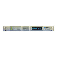
Comtech EF Data SDM-300A Operator's Manual (44 pages)
Brand:
Comtech EF Data
| Category:
Modem
| Size: 0 MB
Table of Contents
Table of Contents
9
About this Manual
11
1 Introduction
13
Title Box
13
Revision History
13
Equipment
15
Equipment Rack Elevation
15
Equipment View
15
Equipment Rack Wiring Diagram
15
2 Equipment View
19
CIM-300L
26
CIM-550
27
CDM-550
28
CDM-600
29
Sdm-300A
30
SDM-2020 Modulator
31
SDM-2020 Demodulator
32
Required Equipment
35
Typical Rack Installation
36
Workstation
36
Snm-1000
36
Sms-301
37
Rack Installation
38
Snm-1001
39
Wiring Connections
40
Snm-1002
40
Equipment Rack History
41
Advertisement
Related Products
Comtech EF Data SDM-100A
Comtech EF Data SDM-300L3
Comtech EF Data SDM-309B
Comtech EF Data SDM-650B
Comtech EF Data SDM-9000
Comtech EF Data SLM-5650
Comtech EF Data SNM-1001L
Comtech EF Data SLM-5650B
Comtech EF Data SLM-3650
Comtech EF Data SLM-5650C CyberLynx
Comtech EF Data Categories
Modem
Switch
Amplifier
Network Router
Media Converter
More Comtech EF Data Manuals
Login
Sign In
OR
Sign in with Facebook
Sign in with Google
Upload manual
Upload from disk
Upload from URL