Sign In
Upload
Manuals
Brands
Comtech EF Data Manuals
Modem
SDM-300L3
Comtech EF Data SDM-300L3 Manuals
Manuals and User Guides for Comtech EF Data SDM-300L3. We have
1
Comtech EF Data SDM-300L3 manual available for free PDF download: Installation And Operation Manual
Comtech EF Data SDM-300L3 Installation And Operation Manual (408 pages)
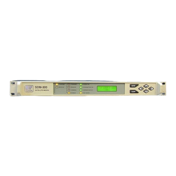
Satellite Modem
Brand:
Comtech EF Data
| Category:
Modem
| Size: 5 MB
Table of Contents
Installation and Operation Manual
1
Customer Support
4
Table of Contents
5
About this Manual
15
Related Documents
15
Electrical Safety
17
Limitations of Warranty
20
Chapter 1. Introduction
21
Figure 1-1. Block Diagram
22
Overview
23
Options Summary
23
Chapter 13. Fully Accessible System Topology (Fast)
23
Comtech EF Data Part Numbers
24
FAST Accessible Options
25
Table 1-1. FAST Options and Required Configurations
25
Compatibility
26
Description of the Modulator
26
Overview
26
Description
26
Description of Modulation Types
27
BPSK Encoding
28
QPSK Encoding
28
OQPSK Encoding
29
8-PSK Encoding
29
Description of the Demodulator
30
Overview
30
Figure 1-2. Demodulator Block Diagram
30
Functional Description
31
Description of Monitor & Control
32
Overview
32
Functional Description
33
Dimensional Envelope
35
Figure 1-4. Dimensional Envelope Drawing
35
Chapter 2. Installation/ Upgrades
37
Unpacking
37
Installation
38
Figure 2-1. Installation of the Optional Mounting Bracket KT/6228-1
39
Software and Hardware Installation/Upgrades
40
Overhead Interface PCB Installation
40
Figure 2-2. Overhead Interface PCB Installation
41
Reed-Solomon PCB
42
Figure 2-3. Reed-Solomon Codec Installation
43
Turbo Codec Installation
44
Figure 2-4. Turbo Codec Installation
46
Data I/O Interface Connector (J8) Removal/Installation
47
Table 2-1. Connector (J8) Matrix
47
Figure 2-5. Data I/O Connector (J8) Removal/Installation
49
Hardware Upgrades
50
Main PCB Firmware Chips
50
Overhead Interface PCB Firmware Chips
50
Figure 2-6. Overhead Board with Field-Changeable Chips
51
Figure 2-7. Main Board Field-Changeable Chips (Shown with Overhead Card Removed)
51
Flash Upgrading
52
Downloading Flash Updates from the Web
53
How to Download Flash Upgrade Files
53
How to Perform a Flash Upgrade
53
Chapter 3. Connector Pinouts
55
Connector Overview
55
Figure 3-1. SDM-300L3 Rear Panel
56
Table 3-1. Modem Rear Panel Connectors
56
Connector Description
57
Remote Connector and Pinouts (J6)
57
Table 3-2. Remote Connector and Pinouts (J6)
57
Fault Connector and Pinouts (J7)
58
Table 3-3. Fault Connector and Pinouts (J7)
58
Data I/O Interface Connector (J8)
59
Table 3-4. 25-Pin D Connector Pinouts
60
Table 3-5. 34-Pin Winchester Connector Pinouts (V.35)
61
Table 3-6. 37-Pin Connector Pinouts (Optional)
62
Table 3-7. 50-Pin Connector Pinouts
63
G.703 T1, E1/ASYNC Interface Adapter
65
Auxiliary 1 Connector and Pinouts (J9)
66
Table 3-8. AUX 1 Connector and Pinouts (J9)
66
Alarms Connector and Pinouts (J10)
67
RF Output Connector (CP1)
67
External Reference (CP2)
67
RF Input Connector (CP3)
67
Table 3-9. Alarms Connector and Pinouts (J10)
67
AC Power Connector
68
Ground Connector (GND)
68
Chapter 4. Front Panel Operation
69
Front Panel
69
Figure 4-1. Front Panel View
69
LED Indicators
70
Table 4-1. LED Indicators
70
Front Panel Keypad
71
Figure 4-2. Keypad
71
Menu System
72
Revision Emulation
73
Power Class
74
Menu Tree
74
Figure 4-3. Menu Tree
74
Opening Screen
75
Function Select: Configuration
75
Carrier Mode
81
Modem Reference
81
Odu 10 Mhz Ref
83
Figure 4-4. RF Loopback
89
Figure 4-5. if Loopback
90
Figure 4-6. Baseband Loopback
98
Figure 4-7. Interface Loopback
99
Function Select: Monitor
133
Function Select Faults/Alarms
136
Backward Alarms
140
Function Select Stored Flts/Alms
142
FUNCTION SELECT: REMOTE AUPC (Conditional)
147
Function Select: Utility
158
Descrambler Type
164
SDM-300L Custom Modem Defaults
197
Table 4-2. SDM-300L Custom Modem Defaults
197
Table 4-2. SDM-300L Custom Modem Defaults (Continued)
198
Chapter 5. Modem Type
201
Modem Type
201
Table 5-1. Modem Type Selection
201
IDR Operation
202
Table 5-2. IDR Parameter Settings
202
309 IBS Operation
203
VSAT IBS Operation
203
D&I Operation
204
Table 5-4. D&I Parameter Settings
204
ASYNC/AUPC Operation
205
Closed Network Operation (Comtech EF Data)
206
Custom Operation
208
Reed-Solomon Modes
209
Table 5-8. Reed-Solomon Modes
209
Chapter 6 . Clocking and Rx Buffering Settings
211
Clocking Options
211
EIA-232, EIA-422, or V.35 Master/Master
211
EIA-232, EIA-422, or V.35 Master/Slave
211
IDR/IBS G.703 Master/Master
212
IDR/IBS G.703 Master/Slave
212
D&I G.703 Master/Master
213
Buffering
219
Figure 6-7. Doppler Shift
221
Doppler
222
Plesiochronous
223
Asymmetrical Loop Timing
224
Figure 6-8. Transmit Section of the Asymmetrical Loop Timing Block Diagram
225
Figure 6-9. Receive Section of the Asymmetrical Loop Timing Block Diagram
226
Frame/Multiframe Length
227
Multiples of the Frame Length
227
Total Buffer Length
227
Converting between Bits and Seconds
228
Chapter 7. Fec and Turbo
229
Introduction
229
Coding
230
Turbo Product Codec (Hardware Option)
230
Introduction
230
Table 7-1. Available TPC Modes
230
Mod/Demod Processing Delay
231
Table 7-2. Turbo Product Coding Processing Delay Comparison
231
Comparison of All TPC Modes
232
Uncoded Operation (no FEC)
233
Figure 7-1. Viterbi Decoder
235
Figure 7-2. Viterbi Decoder and Reed-Solomon
236
Figure 7-3. BPSK and (O)QPSK BER Performance
237
Figure 7-4. Turbo Product Codec
238
Figure 7-5. Sequential Decoder, Reed-Solomon, and 1544 Kbps
239
Figure 7-6. Sequential Decoder and 56 Kbps
240
Figure 7-7. Sequential Decoder and 1544 Kbps
241
Chapter 8. System Checkout
243
Interface Checkout
244
Figure 8-1. Fault Isolation Test Setup
244
Modulator Checkout
245
Table 8-1. Conversion to S/N and Eb/N0 Chart
246
Demodulator Checkout
247
Figure 8-2. Typical Output Spectrum
247
Figure 8-3. Typical Eye Constellations
248
Chapter 9. Fault Isolation
249
System Faults/Alarms
250
Faults/Alarms Display
250
Faults/Alarms Analysis
250
Figure 9-1. SDM-300L Fault Tree
251
Modulator Faults
254
Demodulator Faults
255
Common Equipment Faults
256
Introduction
259
Chapter 10. Open Network Operations
260
Figure 10-1. IBS Interface Block Diagram
261
Table 10-1. IBS Modem Defaults
262
Figure 10-2. IDR Interface Block Diagram
265
Table 10-2. IDR Modem Defaults
266
Drop & Insert (D&I)
267
Figure 10-3. D&I with Asynchronous Overhead Data Flow
268
Description of D&I Operation
269
Plesiochronous Buffer
270
Backward Alarm
271
D&I Framing Formats
272
Figure 10-4. E1 Framing Formats
273
Figure 10-5. T1 Framing Formats
274
Table 10-3. D&I Modem Faults
275
D&I Modem Defaults
275
Xadpcm Voice in 64 Kbps IBS
276
Chapter 11. Asynchronous Interface/Aupc
277
Figure 11-1. ASYNC/AUPC Block Diagram
279
Aupc
280
Table 11-1. Setting AUPC Parameters
280
AUPC – between Two Modems
281
Self-Monitoring Local Modem AUPC Control
282
Terrestrial Data Interfaces
283
ASYNC Data Interfaces
283
MUX Operation
284
DEMUX Operation
284
Buffer Operation
284
Loop Timing Operation
285
Baseband Loopback Operation
285
Non-ASYNC Operation
286
ASYNC Channel EIA-485 2- and 4-Wire Operation
286
Valid ASYNC Baud Rates
287
Front Panel Operation
287
ASYNC Remote Operation
288
Figure 11-3. Remote ASYNC Connection Diagram for Breakout Panel
289
Table 11-3. Local EIA-232 to Remote EIA-232
290
Table 11-4. Local EIA-232 to Remote EIA-485 (4-Wire)
291
Table 11-5. Local EIA-232 to Remote EIA-485 (2-Wire)
292
Table 11-6. Local EIA-485 (4-Wire) to Remote EIA-232
293
Table 11-7. Local EIA-485 (4-Wire) to Remote EIA-485 (4-Wire)
294
Table 11-8. Local EIA-485 (4-Wire) to Remote EIA-485 (2-Wire)
295
Table 11-9. Local EIA-485 (2-Wire) to Remote EIA-232
296
Table 11-10. Local EIA-485 (2-Wire) to Remote EIA-485 (4-Wire)
298
Table 11-11. ASYNC/AUPC Modem Defaults
300
Chapter 12. G.703
301
Table 12-1. G.703 Specifications
301
Fast System Theory
303
Activation Procedure
304
Chapter 14. Specifications
307
Figure 14-1. Block Diagram
308
Specification Summary
309
L-Band Modulator Specification Summary
310
Demodulator Specification Summary
311
L-Band Modulator Specifications
312
Digital Data Rate
312
Modulation and Encoding Types
314
Scrambling Types
315
Modulator Frequency Reference
315
Modulator Spurious Emissions
316
Modulator Phase Noise
316
Modulator if Output Spectrum Shape
316
L-Band INMARSAT Spurious Emissions
316
Differential Encoder
317
BPSK Bit Ordering
317
Interleaver (Reed-Solomon Codec)
317
Modulator Transmit Frequency (IF)
317
Transmit Frequency Change Time
317
Modulator Transmit if Output Switch
317
Modulator Transmit if Power
317
Modulator Power Offset
318
Modulator I / Q Imbalance
318
Modulator Output Noise Floor
318
Modulator Spectrum Rotation
318
Modulator Output Return Loss
318
L-Band ODU Reference Signal
318
L-Band ODU Control and Monitor
318
Modulator Transmit if Test Modes
318
L-Band ODU Supply Voltage
319
ODU DC Current Sense
319
BPSK Encoding
319
OQPSK Encoding
320
L-Band Demodulator Specifications
321
Digital Data Rate
321
Demodulation and FEC Decoding Types
323
Descrambling Types
324
Differential Decoder
324
BPSK Bit Ordering
324
Deinterleaver (Reed-Solomon Codec)
324
Demodulator Spectrum Rotation
325
Receive Frequency
325
Input Overload
325
Demodulator Input Return Loss
325
LNB Prime Power
325
LNB Band Control
325
LNB Reference Signal
325
Receive Input Power (Composite)
326
Demodulator Input Shape
326
Receive Input Power (Desired Carrier)
327
Demodulator Channel Spacing/Adjacent Carrier Performance
327
Figure 14-2. Carrier Level Vs Symbol Rate
327
Bit Error Rate Performance
328
Performance with Noise, Viterbi Decoder, and Closed Network
328
Performance with BPSK and {O}QPSK BER Performance
328
Performance with Noise Turbo Product Codec (Optional)
329
Performance with Noise, 1544 Kbps Sequential Decoder and Reed Solomon(Optional)
329
Performance with Noise, 56 Kbps Sequential Decoder (Optional)
329
Performance with Noise, 1544 Kbps Sequential Decoder (Optional)
330
BER Threshold
330
Acquisition Time
331
Receive Carrier Acquisition Range
332
Receive Carrier Reacquisition
332
AGC Output
332
Doppler Tracking Performance
332
Interface Specifications
333
TX Clock Switching Due to Failure of Selected Clock
333
TX Clock Phase Adjustment
333
TX Data Phase Adjustment
333
Transmit Clock Source
333
Send Clock Timing Source
333
Doppler/Plesiochronous Buffer Clock Source
334
RX Clock Switching Due to Failure of Selected Clock
334
RX Clock Phase Adjustment
334
RX Clock Jitter
334
RX Data Phase Adjustment
334
Buffer Centering
334
Receive Doppler/Plesiochronous Buffer Size
335
Switch Faults
335
Decoding
335
BPSK Decoding
335
QPSK Decoding
335
OQPSK Decoding (Optional)
336
Terrestrial Interface Types
337
EIA-232 Specification
337
V.35 Specification V.10, V.11 Specification, Circuit Supported
338
EIA-449/EIA-422 Mil-188-114A Specification
339
Optional G.703 with ASYNC (Requires Optional Overhead Card)
339
Asynchronous Overhead Specification (Optional)
340
Asynchronous Baud Rates
341
Asynchronous Overhead Data Format
341
Asynchronous Overhead Parameters
341
AUPC with Reed-Solomon Option
341
Turbo AUPC
342
IBS (Optional with Overhead Card)
342
IBS Primary Data Interfaces
342
IBS Clock and Dejitter
342
IBS Framing
342
IBS Engineering Service Channel
343
IBS Scrambling
343
Drop and Insert (Optional with Overhead Card)
343
D&I Primary Data Interfaces
344
D&I Framing
344
IDR (Optional with Overhead Card)
344
IDR Primary Data Interfaces
345
IDR Framing
345
IDR Engineering Service Channel
345
Optional: Dual 32 Kpps ADPCM (2XASPCM Audio)
345
System Specifications
346
Loopback Modes
346
Test Modes
346
Remote Control
347
Modem Remote Address
347
Monitored Signals
347
Stored Faults
348
Stored Configurations
348
Interoperability Modes
348
Chapter 15. Buc Fsk Communications
349
Introduction
349
Message Structure
350
Command Message Structure (IDU to ODU)
350
Response Message Structure (BUC to IDU)
351
APPENDIX B. Burst Mode Modulator Operation
399
Metric Conversions
407
Advertisement
Advertisement
Related Products
Comtech EF Data SDM-309B
Comtech EF Data SDM-300A
Comtech EF Data SDM-100A
Comtech EF Data SDM-650B
Comtech EF Data SDM-9000
Comtech EF Data SLM-5650
Comtech EF Data SLM-7650
Comtech EF Data SNM-1001L
Comtech EF Data SMS-301
Comtech EF Data SLM-5650C CyberLynx
Comtech EF Data Categories
Modem
Switch
Amplifier
Network Router
Media Converter
More Comtech EF Data Manuals
Login
Sign In
OR
Sign in with Facebook
Sign in with Google
Upload manual
Upload from disk
Upload from URL