Sign In
Upload
Manuals
Brands
Alcatel-Lucent Manuals
Radio
9500
Alcatel-Lucent 9500 Manuals
Manuals and User Guides for Alcatel-Lucent 9500. We have
3
Alcatel-Lucent 9500 manuals available for free PDF download: User Manual, Brochure
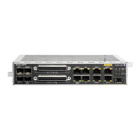
Alcatel-Lucent 9500 User Manual (317 pages)
MICROWAVE PACKET RADIO for ANSI and ETSI
Brand:
Alcatel-Lucent
| Category:
Receiver
| Size: 8.27 MB
Table of Contents
Table of Contents
5
List of Tables
15
List of Figures
19
Preface
33
Preliminary Information
33
Copyright Notification
33
Information
33
Safety Recommendations
33
Warranty
33
Service Personnel Skill
34
Applicability
34
Table 1 - Product and Release
34
Scope
35
History
35
Table 2 - Change History
35
Change Notes
36
Manual Structure
36
Table 3 - Manual Structure
36
1 FCC Part 15 Subpart B
39
9558Hc Unlicensed Radio
39
FCC Class B Compliance Statement
39
FCC Class B Requirements
39
2 Safety, EMC, EMF, ESD Norms, Equipment Labeling, Standards and Compliance
41
MPR-E: Declaration of Conformity to CE Marking and Countries List
41
Figure 2.1 - Declaration of Conformity
42
Specific Label for MPR Equipment
43
Table 2.1 - Labels for MPR Equipment
43
Figure 2.2 - MPT-MC/MPT-HC V2/MPT-XP/9558HC Label
43
Figure 2.3 - MPT-MC/MPT-HC V2/MPT-XP/9558HC Label (Close-Up)
43
Applicable Standards and Recommendations
44
Safety Rules
44
General Rules
44
Dangerous Electrical Voltages
46
Labels Indicating Danger, Forbidding, Command
46
Moving Mechanical Parts: Labeling and Safety Instructions
47
Risks of Explosions: Labeling and Safety Instructions
47
Equipment Connection to Earth: Labeling and Safety Instructions
48
Harmful Optical Signals: Labeling and Safety Instructions
48
Heat-Radiating Mechanical Parts: Labeling and Safety Instructions
48
Microwave Radiations Electromagnetic Field (EMF) Norms: Labeling and Safety Instructions
49
Electromagnetic Compatibility (EMC Norms)
50
Equipment Protection against Electrostatic Discharges
51
Cautions to Avoid Equipment Damage
51
Anti-Static Protection Device Kit
52
Cable Disconnection / Connection
52
Screw Fixing
52
MPR-E: Waste from Electrical and Electronic Equipment (WEEE)
52
Figure 2.4 - Anti-Static Protection Device Kit
52
Standards and Compliance
53
Table 2.2 - Standards and Compliance
53
3 Product Information and Planning
55
9500 Family Overview
55
Figure 3.1 - 9500 MPR Configurations
56
Figure 3.2 - Multiservice Aggregation Layer
58
Figure 3.3 - Service Awareness
59
Figure 3.4 - Packet Node
59
9500 MPR System Family
60
Figure 3.5 - Service-Driven Packet Adaptive Modulation
60
Figure 3.6 - 9500 MPR System Family
61
Family Elements Described in this User Manual
62
The MPR-E Solution
62
The MSS-1C Solution
62
MSS-1C
63
Ethernet Generic Device Prerequisites
64
MPR-E
64
7705 SAR Platform Prerequisites
65
Mpt-Hc V2/Hc-Hqam/9558Hc
66
Figure 3.7 - 11 Ghz MPT-HC V2
68
MSS-1C to MPT-HC/HC-HQAM/9558HC Interconnection
68
Figure 3.8 - MPT-HC/HC-HQAM/9558HC Connection
69
Figure 3.9 - MPT-HC/HC-HQAM/9558HC Connection
70
MSS-1C)
70
MPT-HC/HC-HQAM/9558HC Connectivity for MPR-E (1+0 Configuration)
71
Station Battery)
71
Figure 3.11 - MPT-HC/HC-HQAM/9558HC Connection through the Power Injector Box
73
Figure 3.12 - MPT-HC/HC-HQAM/9558HC Connection through the Power Injector Card Installed
74
In the 7705 SAR
74
Figure 3.13 - MPT-HC/HC-HQAM/XP/XP-HQAM/9558HC Connection through the MPT Extended
75
Power Unit
75
Figure 3.14 - AC Power Converter
76
Figure 3.15 - AC Power O-Ring Pigtail Cable Assembly
76
Table 3.1 - AC Power Converter Features
76
Table 3.2 - AC Power Converter O-Ring Pigtail Cable Features
76
Figure 3.16 - Modified AC Power O-Ring Pigtail Cable
77
Figure 3.17 - MPT-HC/HC-HQAM/9558HC Connection
78
To MPT Power Unit)
78
Figure 3.18 - MPT-HC/HC-HQAM/9558HC Connection (Optical Cable for Traffic and Coaxial Cable to MPT Extended Power Unit)
79
Cable for Power Supply)
80
MPT-HC/HC-HQAM/9558HC Connectivity for MPR-E (Co-Channel XPIC Configuration)
80
(Co-Channel XPIC)
81
Figure 3.20 - MPT-HC/HC-HQAM/9558HC Connection through the Power Injector Box
81
(Co-Channel XPIC)
82
Figure 3.21 - MPT-HC/HC-HQAM/9558HC Connection through the MPT Extended Power Unit
82
Figure 3.22 - MPT-HC/HC-HQAM/9558HC Connection through the Power Injector Card Installed
83
In the 7705 SAR (Co-Channel XPIC)
83
MPT-HC/HC-HQAM/9558HC Connectivity for MPR-E (1+1 HSB in Single NE Mode with 7705 SAR)
83
Figure 3.23 - 1+1 HSB for MPT-HC (11-38 Ghz)
84
Mpt-Xp/Xp-Hqam
84
Figure 3.24 - MPT-XP
85
MSS-1C to MPT-XP/XP-HQAM Interconnection
85
Sparing Strategy: MPT-HC/XP Replacement with MPT-HC-HQAM/XP-HQAM
85
Figure 3.25 - MPT-XP/XP-HQAM Connection
86
Figure 3.26 - MPT-XP/XP-HQAM Connection
87
From Extended Power Unit)
87
MPT-XP/XP-HQAM Connectivity for MPR-E (1+0 Configuration)
87
Figure 3.27 - MPT-XP/XP-HQAM Connection through the MPT Extended Power Unit
88
Extended Power Unit)
89
Figure 3.28 - MPT-XP/XP-HQAM Connection
89
MPT-XP/XP-HQAM Connectivity for MPR-E (Co-Channel XPIC Configuration)
89
Figure 3.29 - MPT-XP/XP-HQAM Connection through the MPT Extended Power Unit
90
MPT-XP/XP-HQAM Connectivity for MPR-E (1+1 HSB in Single NE Mode with 7705 SAR)
90
Xpic)
90
Figure 3.30 - 1+1 HSB for MPT-XP (11-38 Ghz)
91
Mpr-E: Mpt-MC
91
Figure 3.31 - MPT-MC
92
MSS-1C to MPT-MC Interconnection
92
Figure 3.32 - MPT-MC Connection
93
MPT-MC Connectivity for MPR-E
93
Figure 3.33 - MPT-MC Connection through the Power Injector Box
94
Antennas
95
Figure 3.34 - MPT-MC Connection through the Power Injector Card Installed in the 7705 SAR
95
MPR-E: Radio Capacity, Channeling and Modulation
96
MPR-A: Radio Capacity, Channeling and Modulation (MPT-HC/HC-HQAM/XP/XP-HQAM/9558HC)
96
Standard Features
96
Radio Configurations
97
1+0 in Split-Mount Configuration for MSS-1C
97
2X(1+0) Repeater Configuration for MSS-1C
98
Figure 3.35 - 1+0 in Split-Mount Configuration
98
Typical System Configurations for MSS-1C
99
Figure 3.36 - 2X(1+0) Repeater Configuration
99
Figure 3.37 - TDM over Ethernet Packet Node - Mapping of E1/T1/DS1 TDM on Ethernet
100
Figure 3.38 - TDM and Ethernet Terminal Packet Transport E1/T1/DS1 TDM and 1 Radio Direction
100
Environmental and Electrical Characteristics
101
Directions -2X(1+0) Repeater
101
General Characteristics (MSS-1C)
101
Table 3.3 - General Characteristics (MSS-1C)
102
General Characteristics (MPT-HC/HC-HQAM/MC/XP/XP-HQAM/9558HC)
103
Table 3.4 - General Characteristics (MPT-HC/HC-HQAM/MC/XP/XP-HQAM/9558HC)
103
5.8 to 11 Ghz
104
MPR-E: MPT-HC/HC-HQAM/XP/XP-HQAM Characteristics
104
Table 3.5 - Environmental Characteristics (MPT-HC/HC-HQAM/MC/XP/XP-HQAM/9558HC)
104
Table 3.6 - MPT-HC/HC-HQAM Characteristics, 5.8 to 11 Ghz (MPR-E)
104
13 To 38 Ghz
105
MPT-XP/XP-HQAM Characteristics
106
Table 3.7 - MPT-HC/HC-HQAM Characteristics, 13 to 38 Ghz (MPR-E)
106
MPR-E: MPT-MC Characteristics
107
Table 3.8 - MPT-XP/XP-HQAM Characteristics, 6 to 8 Ghz (MPR-E)
107
To 13 Ghz
107
15 To 38 Ghz
108
Table 3.10 - MPT-MC Characteristics, 15 to 38 Ghz (MPR-E)
108
Table 3.9 - MPT-MC Characteristics, 6 to 13 Ghz (MPR-E)
108
5.8 to 11 Ghz
109
MPR-A: MPT-HC/HC-HQAM/9558HC Characteristics
109
Table 3.11 - MPT-HC/HC-HQAM/9558HC General Characteristics (MPR-A)
109
15 To 38 Ghz
110
Table 3.12 - MPT-HC/HC-HQAM/9558HC Characteristics, 15 to 38 Ghz (MPR-A)
110
MPR-A: MPT-XP/XP-HQAM Characteristics
111
Table 3.13 - MPT-XP/XP-HQAM Characteristics, 6 to 8 Ghz (MPR-A)
111
To 8 Ghz
111
MPT Power System: Power Requirements
112
Table 3.14 - MPT-XP Power System: Power Requirements
112
Table 3.15 - MPT-HC Power System: Power Requirements
114
Radio Performances
115
General Characteristics (MPT Power Unit)
116
General Characteristics (Power Injector)
116
Table 3.16 - Power Injector General Characteristics
116
Table 3.17 - MPT Power Unit General Characteristics
116
MPR-A: Maximum Allowed Cable Lengths for MPT Power Unit
117
MPR-E: Maximum Allowed Cable Lengths for MPT Power Unit
117
Table 3.18 - Maximum Allowed Cable Lengths for MPT Power Unit (MPR-E)
117
General Characteristics (MPT Extended Power Unit)
118
Table 3.19 - Maximum Allowed Cable Lengths for MPT Power Unit (MPR-A)
118
Table 3.20 - MPT Extended Power Unit General Characteristics
118
MPR-E: Maximum Allowed Cable Length for MPT Extended Power Unit
119
Table 3.21 - Maximum Allowed Cable Lengths for MPT Extended Power Unit (MPR-E)
119
MPR-A: Maximum Allowed Cable Length for MPT Extended Power Unit
120
Table 3.22 - Maximum Allowed Cable Lengths for MPT Extended Power Unit (MPR-A)
120
MPR-E Parts Lists
121
MPR-E Indoor Items for MPR-E Solution
121
MSS-1C Item Codes
121
Table 3.23 - MPR-E MSS-1C Item Codes
121
Table 3.24 - MPR-E: Indoor Items for MPR-E Solution
121
CD-ROM Software
122
Table 3.25 - MPR-E: CD-ROM Software
122
MPT-HC V2/HC-HQAM with Internal Diplexer
123
MPT-HC V2/MPT-XP External Modules (Option for MPR-E)
123
MPT-HC V2/MPT-XP Optical Interface Option
123
MPT-HC/HC-HQAM/MC/XP/XP-HQAM/ with External Diplexer
123
MPT-MC with Internal Diplexer
123
Table 3.26 - MPR-E: MPT-HC V2/MPT-XP Option
123
External Diplexer MPT-HC/HC-HQAM/MC/XP/XP-HQAM
124
Figure 3.40 - MPT-HC/HC-HQAM/MC/XP/XP-Hqam/With External Diplexer - Diplexer as a 3-Port
124
Figure 3.41 - MPT-HC/HC-HQAM/MC/XP/XP-HQAM/ with External Diplexer - Arrangement between each Filter on the same External Diplexer Device
124
MPT-HC/HC-HQAM/MC/XP/XP-HQAM Couplers for MPR-E
124
Passive Device with Two Band-Pass Filters
124
MPT-HC/HC-HQAM/XP/XP-HQAM Optical Interface
125
Table 3.27 - MPT-HC/HC-HQAM/XP/XP-HQAM 1+1 Couplers for MPR-E
125
Table 3.28 - MPT-HC/HC-HQAM/XP/XP-HQAM OMT Couplers for MPR-E
125
MPR-A Parts Lists
126
MSS-1C Items
126
Table 3.29 - MPT-HC/MPT-XP Optical Interface
126
Table 3.30 - MPR-A: MSS-1C Items
126
CD-ROM Software
127
Indoor Items for MPR-E Solution
127
MPT-HC/HC-HQAM/XP/XP-HQAM/9558HC Optical Interface Option
127
Table 3.31 - MPR-A: Indoor Items for MPR-E Solution
127
Table 3.32 - MPR-A: CD-ROM Software
127
MPT-HC V2/HC-HQAM with Internal Diplexer
128
MPT-HC/HC-HQAM/XP/XP-HQAM/9558HC External Modules (Option for MPR-E)
128
MPT-HC/HC-HQAM/XP/XP-HQAM/9558HC with External Diplexer
128
Table 3.33 - MPR-A: MPT-HC V2/MPT-XP/9558HC Option
128
Table 3.34 - MPR-A:MPT-HC/HC-HQAM/XP/XP-HQAM/9558HC External Modules
128
3-Port Passive Device with Two Band-Pass Filters
129
Between each Filter on the same External Diplexer Device
129
External Diplexers for MPT-HC/HC-HQAM/XP/XP-HQAM/9558HC
129
Figure 3.42 - MPT-HC/HC-HQAM/XP/XP-HQAM/9558HC with External Diplexer - Diplexer Is a
129
Figure 3.43 - MPT-HC/HC-HQAM/XP/XP-HQAM/9558HC with External Diplexer - Arrangement
129
MPT-HC/HC-HQAM/XP/XP-HQAM/9558HC Without External Diplexer
129
MPT-HC/HC-HQAM/XP/XP-HQAM/9558HC Couplers for MPR-E
130
Table 3.35 - MPT-HC/HC-HQAM/XP/XP-HQAM 1+1 Couplers for MPR-E
130
Table 3.36 - MPT-HC/HC-HQAM/XP/XP-HQAM OMT Couplers for MPR-E
130
Functional Description
131
MSS-1C (Indoor Unit)
131
Table 3.37 - MPT-HC/HC-HQAM/XP/XP-HQAM Optical Interface
131
Figure 3.44 - MSS-1C Block Diagram
132
Figure 3.45 - MSS-1C Front View
132
External User Interface
133
Figure 3.46 - MSS-1C Rear View
133
E1/T1 Interface
134
Ethernet Switch
134
Power Supply
134
Traffic 10/100/1000 Base-T Ethernet Interfaces for Data and Service Traffic Via RJ45 Connector
134
Ethernet User Interface
135
MPT Interface
135
Figure 3.47 - MSS-1C and Fan Unit
136
Mpt-Hc/Hc-Hqam/Xp/Xp-Hqam/9558Hc
136
MSS-1C Fan Unit
136
Table 3.38 - MPT Odus that Support an Embedded Diplexer
137
Figure 3.48 - MPT-HC Housing (Embedded Diplexer)
138
Figure 3.49 - Correct Protected Mounting of 6 Ghz MPT-XC with Internal and External Diplexers
139
Diplexers
140
Figure 3.50 - Incorrect Protected Mounting of 6 Ghz MPT-XC with Internal and External
140
Figure 3.51 - View of MPT-HC-HQAM with External Diplexer (13-38 Ghz)
141
Table 3.39 - MPT Odus that Support an External Diplexer
141
Figure 3.52 - MPT-HC V2/MPT-XP/9558HC Housing
142
Figure 3.53 - MPT-HC V2 Housing (Internal Diplexer)
142
Figure 3.54 - MPT-HC V2/MPT-XP/9558HC Housing (External Diplexer)
143
RSSI Monitoring Point
143
Table 3.40 - RSSI
143
Table 3.41 - MPR-E Waveguide Flange Data
143
Waveguide Flange Data
143
Mpt-MC (Mpr-E)
144
Table 3.42 - MPR-A Waveguide Flange Data
144
Figure 3.55 - MPT-MC Housing (Internal Diplexer)
145
Figure 3.56 - MPT-MC Housing (External Diplexer)
145
General
145
Power Injector
145
Figure 3.57 - Power Injector Card
146
Figure 3.58 - Power Injector Box
146
Main Functions of the Power Injector
146
Power Injector Versions
146
Connectors
147
Figure 3.59 - Power Injector Front Panel
147
Figure 3.60 - MPT Power Unit
147
Leds
147
MPT Power Unit
147
Figure 3.61 - MPT Extended Power Unit
148
Leds
148
MPT Extended Power Unit
148
Automatic Transmit Power Control (ATPC)
149
Frequency Agility
149
Radio Transmission Features with MPT-HC/HC-HQAM/MC/XP/XP-HQAM/9558HC
149
Transmitted Power Control: RTPC Function
149
1+0 Repeater (with MPT-HC/HC-HQAM/XP/XP-HQAM/9558HC Only, for MPR-E)
150
Adaptive Equalization
150
Power Monitoring
150
Figure 3.62 - 1+0 Repeater Configuration
151
XPIC (with MPT-HC/HC-HQAM/XP/XP-HQAM Only, for MPR-E)
151
Figure 3.63 - Co-Channel XPIC
152
1+1 Hot Standby for MPR-E
154
Figure 3.64 - Auto TX Mute in XPIC Configuration
154
Figure 3.65 - Available Loopbacks
155
Link Identifier
155
Loopbacks
155
Loopback Activation
156
Loopback Life Time
156
MPR-A: Unlicensed Radio for 9558HC
157
Table 3.43 - Unlicensed Radio
157
Table 3.44 - 5.8 Ghz Unlicensed Antenna Options
158
Figure 3.66 - Frequency Plan 9558HC: 5.725 to 5.850 Ghz Unlicensed Band
159
MPR-E Standalone IP Addresses
159
Rss-210)
159
NE IP Addresses
160
TMN Communication Channels
160
TMN In-Band
160
Tmn-Rf
160
MSS-1C Traffic Profiles
161
SAR and MPR-E Single NE IP Addresses
161
Figure 3.67 - Traffic Profiles
162
Figure 3.68 - Traffic Profiles
163
Tdm2Tdm
163
Figure 3.69 - E1 Traffic in TDM2TDM Profile
164
Figure 3.70 - E1 Traffic in Tdm2Eth Profile
165
Tdm2Eth
165
Bridge Type Change
166
Eth2Eth
166
Figure 3.71 - E1 Traffic in ETH2ETH (DATA) Profile
166
MSS-1C Ethernet Traffic Management
166
Reserved Multicast Addresses
167
Table 3.45 - Actions Taken for Specific Reserved Multicast Addresses
167
Figure 3.72 - Qos in the MSS-1C
168
Qos in the MSS-1C
168
Quality of Service (Qos)
168
Table 3.46 - IEEE 802.1P Classification
169
Table 3.47 - Diffserv Classification
169
Figure 3.73 - Qos in the MPT with MSS-1
170
Qos in the MPT
170
Table 3.48 - DWRR Classification
170
Figure 3.74 - Qos in the MPT for MPR-E
171
Table 3.49 - Qos Based on 802.1P Priority
171
Table 3.50 - Qos Based on Diffserv Priority
172
Table 3.51 - Default Weights
172
E1/T1 Cross-Connection
173
Figure 3.75 - Cross-Connection
173
MSS-1C Cross-Connections
173
Figure 3.76 - E1/T1 From/To Radio Port
174
Figure 3.77 - E1/T1 From/To Ethernet Port
174
Ethernet Flows
175
Synchronization
175
Synchronization Overview for MSS-1C
175
Synchronization for MPR-E Standalone and 7705 SAR
178
Table 3.52 - 7705 SAR PMC Card MAC Addresses
179
Synchronization for MPR-E in Single NE Mode with 7705 SAR
181
Automatic Link Discovery
182
Figure 3.78 - LLDP
182
LLDP Overview
182
Default Parameter
183
LLDP on MPR-E
183
Transmitting Nearest Bridge Lldpdus
183
MIB Update Scenarios
184
Receiving Nearest Bridge Lldpdus
184
SNMP MIB Management
184
Supported Tlvs
184
Automatic Link Discovery Scenarios
185
Notifying the SNMP Manager
185
Number of Supported Neighbors at a Time
185
Transparent Relay of Nearest Non-TPMR Bridge and Nearest Customer Bridge Pdus
185
Displaying Neighbors in the MCT
186
Figure 3.79 - Radio Discovery Protocol and Ethernet User Interface LLDP
186
4 NE Management by Software Application
187
Security Session Management
187
Figure 4.1 - Session Expiration Message
187
Webeml Start
188
Figure 4.2 - Connection Lost Message
188
Figure 4.3 - Webeml Desktop Icon
188
Figure 4.4 - Neto Servers Manager
189
Figure 4.5 - Neto Initial Screen
189
Figure 4.6 - Neto Main View with Supervised NE
190
Figure 4.7 - Consent Banner
191
Figure 4.8 - MCT Screen
191
Figure 4.9 - Main View: System Overview for MPR-E
192
Figure 4.10 - Main View: System Overview for MSS-1C
193
Figure 4.11 - Craft User Banner
193
7705 SAR and MPR-E in Single NE: MCT Launcher Start
194
Figure 4.12 - Main View: System Overview with MPT-HC V2/MPT-XP with XPIC Module
194
Figure 4.13 - MCT Launcher Icon
195
Figure 4.14 - MCT Launcher Startup Screen
195
Figure 4.15 - MCT Launcher Main Screen
196
Figure 4.16 - MCT System Overview with 7705 SAR
196
MCT Tool Bar
197
Alarm Synthesis
197
Figure 4.17 - Tool Bar
197
Domain Alarm Synthesis Area
198
General Information on the Management State
199
Figure 4.18 - Radio Synthesis Tab
199
Figure 4.19 - Radio Synthesis Tab with XPIC Configured
199
Figure 4.20 - Network Supervision Tab
199
My Account
200
Figure 4.21 - My Account Menu
200
Figure 4.22 - Change Password Window
201
Figure 4.23 - Change Password Window with OK Button Enabled
201
Figure 4.24 - Password Change Confirmation
201
Navigator Area
202
Figure 4.25 - Password Change Failure
202
Commissioning
203
Figure 4.26 - Inventory
204
Inventory
204
Software Download for MSS-1C
204
Figure 4.27 - Software Download Using FTP
205
Figure 4.28 - Software Download Using SFTP
206
Figure 4.29 - SFTP Fingerprint Window
207
Figure 4.30 - Directory for the SW Component if Apache Server Is in Use
208
Figure 4.31 - Software Download: Active Software Package Summary
209
Figure 4.32 - Software Download: Stand-By Software Package Summary
210
Software Download for MPR-E Standalone
210
Figure 4.33 - Software Download Using FTP
211
Figure 4.34 - Software Download Using SFTP
211
Figure 4.35 - SFTP Fingerprint Window
212
Figure 4.36 - Directory for the SW Component if Apache Server Is in Use
213
Figure 4.37 - Software Download
214
Figure 4.38 - Software Download: Active Software Package Summary
215
Configuration
216
Figure 4.39 - Software Download: Stand-By Software Package Summary
216
Figure 4.40 - Date/Time Configuration
217
Figure 4.41 - Site Information
218
Figure 4.42 - Protection Configuration
219
Figure 4.43 - 1+0 Protection Configuration
220
Figure 4.44 - 1+1 HSB Configuration
221
Figure 4.45 - User Port Menu
222
Figure 4.46 - Optical GE Active Configuration with Synce Synchronization
223
Figure 4.47 - Optical GE Active Configuration with Internal Oscillator
223
Figure 4.48 - Electrical 100 Mb/S Active Configuration with Synce Synchronization
224
Figure 4.49 - Electrical 100 Mb/S Active Configuration with Internal Oscillator
225
(Green LED)
226
Figure 4.50 - Electrical 1 Gb/S Active Configuration with Automatic Synce Synchronization
226
Led)
227
Figure 4.52 - Electrical 1 Gb/S Active Configuration with Manual Synce Synchronization
228
IN or Synce OUT)
228
Figure 4.53 - Electrical 1Gb/S Active Configuration with PCR Synchronization
229
Figure 4.54 - Electrical 1 Gb/S Active Configuration with Internal Oscillator
230
Figure 4.55 - Warning Screen
232
Figure 4.56 - Radio Configuration MPT-HC-HQAM: FCM - RTPC
234
Figure 4.57 - Radio Configuration MPT-HC-HQAM: FCM - ATPC
235
Figure 4.58 - Radio Configuration MPT-HC-HQAM: ACM - RTPC
236
Figure 4.59 - Radio Configuration MPT-HC HQAM: ACM - ATPC
237
Figure 4.60 - XPIC Configuration (MPT-HC-HQAM)
238
Figure 4.61 - XPIC with Horizontal Polarization System Overview
239
Figure 4.62 - XPD
239
Figure 4.63 - Warning Message
240
Figure 4.64 - Advanced Radio Configuration
240
Figure 4.65 - Radio Encryption
242
Figure 4.66 - Set Radio Encryption Passphrase
243
Figure 4.67 - Set Passphrase Window
243
Figure 4.68 - Radio Encryption Set
244
Figure 4.69 - MSS-1C
245
Figure 4.70 - Provisioning Management Menu
245
Figure 4.71 - Provisioning Sub-Menus
246
Table 4.1 - Parameters Leading to a Restart
247
Figure 4.72 - Cancel Button
248
Figure 4.73 - Refresh Button
249
Figure 4.74 - Ethernet Ports Provisioning
251
Figure 4.75 - Cross Connection TDM2TDM (E1 Case)
254
Figure 4.76 - One Shot Tributaries Provisioning
255
Figure 4.77 - Cross Connection Functional Scheme
255
Figure 4.78 - Cross Connection TDM2TDM (T1 Case)
256
Figure 4.79 - Cross Connection to User Ethernet Port
258
Figure 4.80 - Cross Connection Functional Scheme
259
Figure 4.81 - Management Port Provisioning
260
Figure 4.82 - TDM Cross Connection between Radio and Ethernet Port
261
Figure 4.83 - Cross Connection Functional Scheme
262
Figure 4.84 - Network Synchronization Clock Provisioning
263
Figure 4.85 - NE Bridge Mode Selection
264
Figure 4.86 - NE Bridge Mode Selection
266
Figure 4.87 - Port VLAN Provisioning
267
Figure 4.88 - Port VLAN Provisioning
268
Figure 4.89 - Storm Control and Rate Limiting
269
Figure 4.90 - Per Flow Policer
270
Figure 4.91 - Ethernet Traffic Qos
271
Figure 4.92 - IEEE 802.1P
272
Figure 4.93 - Diffserv
273
Figure 4.94 - Ethertype Classification
274
Figure 4.95 - Scheduling Algorithms
274
Figure 4.96 - Cross-Connection Creation
275
Figure 4.97 - TDM2ETH Cross-Connection
276
Figure 4.98 - Cross-Connection Modify
277
Figure 4.99 - Cross-Connection Clone
278
Figure 4.100 - Network Interfaces
279
Figure 4.101 - TMN RF Field
280
Figure 4.102 - Areas
281
Figure 4.103 - OSPF Areas Management
281
Figure 4.104 - Configuration Message
282
Figure 4.105 - Areas
282
Figure 4.106 - Configuration Message
282
Figure 4.107 - Areas
283
Figure 4.108 - Modify OSPF Area
283
Figure 4.109 - Interfaces
283
Figure 4.110 - Network Interfaces Attachment to an OSPF Area
284
Figure 4.111 - Interfaces
284
Figure 4.112 - Network Interfaces Attachment to an OSPF Area
284
Figure 4.113 - Static Routing
285
Figure 4.114 - Routing Table
286
Figure 4.115 - Trusted SNMP Managers
287
Figure 4.116 - Manager Registration
288
Figure 4.117 - MPR-E NE Neighbors Tab
289
Figure 4.118 - MSS-1C NE Neighbors Tab
290
Figure 4.119 - MCT Connected to Main MPT
292
Figure 4.120 - Align Spare MPT Configuration Dialog Box
292
Figure 4.121 - Synchronization Pending
292
Figure 4.122 - Synchronization in Progress
293
Figure 4.123 - MCT Connected to Main MPT with Synchronization Pending
293
Figure 4.124 - MCT Connected to Main MPT with Successful Synchronization Log
294
Figure 4.125 - MCT Connected to Spare MPT
295
Figure 4.126 - MCT Connected to Spare MPT with Successful Synchronization Log
296
Figure 4.127 - Synchronization Failure Dialog Box
296
Backup / Restore
297
Figure 4.128 - MCT Connected to Main MPT with Failed Synchronization Log
297
Figure 4.129 - Backup / Restore Using FTP
298
Figure 4.130 - Backup / Restore Using SFTP
298
Monitoring
299
Performance Monitoring
299
Figure 4.131 - Performance Monitoring Menu
300
Performance History File Upload
300
Figure 4.132 - Performance History File Upload Using FTP
302
Figure 4.133 - Performance History File Upload Using SFTP
302
Figure 4.134 - Qos Ethernet Counter Period Duration
303
Normalized
303
Figure 4.135 - Counters Thresholds
304
Figure 4.136 - 15Min Counter Activation
305
Figure 4.137 - 15Min Counter
306
Figure 4.138 - 15Min Counter Completed
307
Figure 4.139 - 15Min Counter Deactivation
308
Figure 4.140 - Import History
309
Adaptive Modulation
310
Figure 4.141 - File Selection
310
Figure 4.142 - Adaptive Modulation Counter Activation
311
Figure 4.143 - Adaptive Modulation 15Min Counter
311
Figure 4.144 - Adaptive Modulation 15Min Counters History
312
Ethernet Qos
313
Figure 4.145 - 15Min Counters Deactivation
313
Figure 4.146 - Ethernet: QOS Counters
314
Figure 4.147 - Qos Counters Example for Queue 1
315
Traffic Port Ethernet for MPR-E
315
Figure 4.148 - Ethernet: Traffic Port Counters
316
Advertisement
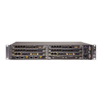
Alcatel-Lucent 9500 User Manual (248 pages)
MICROWAVE PACKET RADIO for ANSI/ETSI
Brand:
Alcatel-Lucent
| Category:
Radio
| Size: 5.61 MB
Table of Contents
Table of Contents
3
List of Tables
11
List of Figures
15
Preface
25
Preliminary Information
25
Copyright Notification
25
Information
25
Warranty
25
Safety Recommendations
26
Service Personnel Skill
26
Applicability
26
Table 1 Product and Release
26
Scope
27
History
27
Table 2 Change History
27
Change Notes
28
Manual Structure
28
Table 3 Manual Structure
28
FCC Part 15 Subpart B
31
9558Hc Unlicensed Radio
31
FCC Class B Compliance Statement
31
FCC Class B Requirements
32
Safety, EMC, EMF, ESD Norms, Equipment Labeling, Standards and Compliance
33
MPR-E: Declaration of Conformity to CE Marking and Countries List
33
Figure 1 Declaration of Conformity
34
Specific Label for MPR Equipment
35
Safety, EMC, EMF, ESD Norms, Equipment Labeling, Standards and Compliance
35
Figure 2 MPT-MC/MPT-HC V2/MPT-XP/9558HC Label
35
Figure 3 MPT-MC/MPT-HC V2/MPT-XP/9558HC Label (Close-Up)
35
Applicable Standards and Recommendations
36
Table 4 Labels for MPR Equipment
36
Safety Rules
37
General Rules
37
Labels Indicating Danger, Forbiddance, Command
38
Dangerous Electrical Voltages
39
Risks of Explosions: Labeling and Safety Instructions
39
Equipment Connection to Earth: Labeling and Safety Instructions
40
Moving Mechanical Parts: Labeling and Safety Instructions
40
Harmful Optical Signals: Labeling and Safety Instructions
41
Heat-Radiating Mechanical Parts: Labeling and Safety Instructions
41
Microwave Radiations Electromagnetic Field (EMF) Norms: Labeling and Safety Instructions
42
Electromagnetic Compatibility (EMC Norms)
43
Equipment Protection against Electrostatic Discharges
44
Cautions to Avoid Equipment Damage
44
Anti-Static Protection Device Kit
45
Figure 4 Anti-Static Protection Device Kit
45
MPR-E Cable Disconnection / Connection
45
Screw Fixing
45
MPR-E: Waste from Electrical and Electronic Equipment (WEEE)
46
Standards and Compliance
46
Table 5 Standards and Compliance
46
Safety, EMC, EMF, ESD Norms, Equipment Labeling, Standards and Compliance
47
Product Information and Planning
49
9500 Family Overview
49
Figure 5 9500 MPR Configurations
50
Figure 6 Multiservice Aggregation Layer
52
Figure 7 Service Awareness
53
Figure 8 Packet Node
53
Figure 9 Service-Driven Packet Adaptive Modulation
54
9500 MPR System Family
55
Figure 10 9500 MPR System Family
55
Ethernet Generic Device Prerequisites
56
Family Elements Described in this User Manual
56
7705 SAR Platform Prerequisites
57
7705 SAR and MPR-E in Single NE Mode
58
7705 SAR and MPR-E Standalone Mode
58
1+1 HSB in Single NE Mode with 7705 SAR Only
59
Mpt-Hc V2/9558Hc
59
Figure 11 11 Ghz MPT-HC V2
60
MPT-HC V2/9558HC Connectivity (1+0 Configuration)
60
Figure 12 MPT-HC V2/9558HC Connection through the Power Injector Box
62
Figure 13 MPT-HC V2/9558HC Connection through the Power Injector Card Installed in the
63
Figure 14 MPT-HC V2/MPT-XP/9558HC Connection through the MPT Extended Power Unit
64
Figure 15 AC Power Converter
65
Figure 16 AC Power O-Ring Pigtail Cable Assembly
65
Table 6 AC Power Converter Features
65
Table 7 AC Power Converter O-Ring Pigtail Cable Features
65
Figure 17 Modified AC Power O-Ring Pigtail Cable
66
Figure 18 MPT-HC V2/9558HC Connection
68
Figure 19 MPT-HC V2/9558HC Connection (Optical Cable for Traffic and Coaxial Cable to MPT Extended Power Unit)
69
Figure 20 MPT-HC V2/9558HC Connection (Optical Cable for Traffic and Coaxial Cable for Power Supply)
70
MPT-HC V2/9558HC Connectivity (Co-Channel XPIC Configuration)
70
Figure 21 MPT-HC V2/9558HC Connection through the Power Injector Box (Co-Channel XPIC)
71
Figure 22 MPT-HC V2/9558HC Connection through the MPT Extended Power Unit (Co-Channel XPIC)
72
Figure 23 MPT-HC V2/9558HC Connection through the Power Injector Card Installed in the 7705 SAR (Co-Channel XPIC)
72
Figure 24 1+1 HSB for MPT-HC (11-38 Ghz)
73
MPT-HC V2/9558HC Connectivity (1+1 HSB in Single NE Mode with 7705 SAR)
73
Mpt-Xp
73
Figure 25 MPT-XP
74
MPT-XP Connectivity (1+0 Configuration)
74
Figure 26 MPT-XP Connection through the MPT Extended Power Unit
75
Figure 27 MPT-XP Connection
76
MPT-XP Connectivity (Co-Channel XPIC Configuration)
76
Figure 28 MPT-XP Connection through the MPT Extended Power Unit (Co-Channel XPIC)
77
MPT-XP Connectivity (1+1 HSB in Single NE Mode with 7705 SAR)
77
Figure 29 1+1 HSB for MPT-XP (11-38 Ghz)
78
Figure 30 MPT-MC
78
Mpr-E: Mpt-MC
78
MPT-MC Connectivity
78
Figure 31 MPT-MC Connection through the Power Injector Box
79
Antennas
80
Figure 32 MPT-MC Connection through the Power Injector Card Installed in the 7705 SAR
80
MPR-E: Radio Capacity, Channeling and Modulation (MPT-HC V2/MPT-MC/MPT-XP)
81
Table 8 MPR-E Modem Profiles (Static Modulation)
81
Product Information and Planning
81
Product Information and Planning
83
Table 9 MPR-E XPIC Modem Profiles for MPT-HC V2 and MPT-XP Only (Static Modulation)
83
Table 10 MPR-E Modem Profiles (Adaptive Modulation)
84
Table 11 MPR-E XPIC Modem Profiles for MPT-HC V2 and MPT-XP Only (Adaptive Modulation)
85
MPR-A: Radio Capacity, Channeling and Modulation (MPT-HC V2 /MPT-XP/9558HC)
86
Radio Configurations
87
Standard Features
87
Environmental and Electrical Characteristics
88
General Characteristics (MPT-HC V2/MPT-MC/MPT-XP (MPR-E)/9558HC (MPR-A))
88
Table 12 General Characteristics (MPT-HC V2/MPT-MC/MPT-XP (MPR-E)/9558HC (MPR-A))
88
Table 13 Environmental Characteristics (MPT-HC V2/MPT-MC/MPT-XP/9558HC)
89
5.8 to 11 Ghz
90
MPR-E: MPT-HC V2/MPT-XP Characteristics
90
Table 14 MPT-HC V2 Characteristics, 5.8 to 11 Ghz (MPR-E)
90
13 To 38 Ghz
91
Table 15 MPT-HC V2 Characteristics, 13 to 38 Ghz (MPR-E)
91
MPT-XP Characteristics
92
Table 16 MPT-XP Characteristics, 6 to 8 Ghz (MPR-E)
92
MPR-E: MPT-MC Characteristics
94
Table 17 MPT-MC Characteristics, 6 to 13 Ghz (MPR-E)
94
To 13 Ghz
94
15 To 38 Ghz
95
5.8 to 11 Ghz
95
MPR-A: MPT-HC V2/9558HC Characteristics
95
Table 18 MPT-MC Characteristics, 15 to 38 Ghz (MPR-E)
95
Table 19 MPT-HC V2/9558HC General Characteristics (MPR-A)
95
15 To 38 Ghz
96
Table 20 MPT-HC V2/9558HC Characteristics, 15 to 38 Ghz (MPR-A)
96
MPR-A: MPT-XP Characteristics
97
Table 21 MPT-XP Characteristics, 6 to 8 Ghz (MPR-A)
97
To 8 Ghz
97
MPT Power System: Power Requirements
98
Table 22 MPT-XP Power System: Power Requirements
99
Radio Performances
100
Table 23 MPT-HC V2 Power System: Power Requirements
100
General Characteristics (MPT Power Unit)
101
General Characteristics (Power Injector)
101
Table 24 Power Injector General Characteristics
101
Table 25 MPT Power Unit General Characteristics
101
MPR-A: Maximum Allowed Cable Lengths for MPT Power Unit
102
MPR-E: Maximum Allowed Cable Lengths for MPT Power Unit
102
Table 26 Maximum Allowed Cable Lengths for MPT Power Unit (MPR-E)
102
Table 27 Maximum Allowed Cable Lengths for MPT Power Unit (MPR-A)
102
General Characteristics (MPT Extended Power Unit)
103
Table 28 MPT Extended Power Unit General Characteristics
103
MPR-E: Maximum Allowed Cable Length for MPT Extended Power Unit
104
Table 29 Maximum Allowed Cable Lengths for MPT Extended Power Unit (MPR-E)
104
Indoor Items
105
MPR-A: Maximum Allowed Cable Length for MPT Extended Power Unit
105
MPR-E Parts Lists
105
Table 30 Maximum Allowed Cable Lengths for MPT Extended Power Unit (MPR-A)
105
Table 31 MPR-E: Indoor Items
105
CD-ROM Software
106
Table 32 MPR-E: CD-ROM Software
106
MPT-HC V2/MPT-XP External Modules (Option)
107
MPT-HC V2/MPT-XP Optical Interface Option
107
Table 33 MPR-E: MPT-HC V2/MPT-XP Option
107
Table 34 MPR-E: MPT-HC V2/MPT-XP External Modules
107
MPT-HC V2 with Internal Diplexer
108
Table 35 MPR-E: MPT-HC V2 with Internal Diplexer
108
MPT-MC with Internal Diplexer
112
Table 36 MPR-E: MPT-MC with Internal Diplexer
112
MPT-HC V2/MPT-MC/MPT-XP with External Diplexer
115
Table 37 MPR-E: MPT-MC High Power with Internal Diplexer
115
External Diplexer MPT-MC, MPT-HC V2, MPT-XP
116
Figure 33 MPT-HC V2/MPT-MC/MPT-XP with External Diplexer - Diplexer as a 3-Port Passive Device with Two Band-Pass Filters
116
Figure 34 MPT-HC V2/MPT-MC/MPT-XP with External Diplexer - Arrangement between each Filter on the same External Diplexer Device
116
Table 38 MPR-E: 6, 7, and 8 Ghz MPT-MC with External Diplexer
116
Table 39 MPR-E: 7/8 Ghz MPT-MC High Power with External Diplexer
117
Table 40 MPR-E: MPT-HC V2 with External Diplexer
117
Table 41 MPR-E: 7/8 Ghz MPT-HC V2 High Power with External Diplexer
118
Table 42 MPR-E MPT-XP with External Diplexer
118
Table 43 MPR-E: 5.8 Ghz External Diplexer Assemblies (for MPT-HC V2 and MPT-MC)
118
Table 44 MPR-E: L6 Ghz External Diplexer Assemblies
119
Table 45 MPR-E: U6 Ghz External Diplexer Assemblies
119
Table 46 MPR-E: 7 Ghz External Diplexer Assemblies (for MPT-MC and MPT-HC V2)
119
Table 47 MPR-E: 7 Ghz High Power External Diplexer Assemblies (for MPT-HC V2, MPT-MC and MPT-XP High Power)
121
Table 48 MPR-E: 8 Ghz External Diplexer Assemblies (for MPT-MC)
122
Table 49 MPR-E: 8 Ghz High Power External Diplexer Assemblies
123
Table 50 MPR-E: 10.5 Ghz External Diplexer Assemblies (for MPT-HC V2 and MPT-MC)
124
MPT-HC V2/MPT-XP Optical Interface
125
Table 51 MPT-HC V2/MPT-XP Couplers
125
Table 52 MPT-HC V2/MPT-XP Optical Interface
125
CD-ROM Software
126
Indoor Items
126
MPR-A Parts Lists
126
Table 53 MPR-A: Indoor Items
126
Table 54 MPR-A: CD-ROM Software
126
MPT-HC V2/MPT-XP/9558HC External Modules (Option)
127
MPT-HC V2/MPT-XP/9558HC Optical Interface Option
127
Table 55 MPR-A: MPT-HC V2/MPT-XP/9558HC Option
127
Table 56 MPR-A: MPT-HC V2/MPT-XP/9558HC External Modules
127
MPT-HC V2 with Internal Diplexer
128
Table 57 MPR-A: MPT-HC V2 with Internal Diplexer
128
MPT-HC V2/MPT-XP/9558HC with External Diplexer
129
Figure 35 MPT-HC V2/MPT-XP/9558HC with External Diplexer - Diplexer Is a 3-Port Passive Device with Two Band-Pass Filters
130
Figure 36 MPT-HC V2/MPT-XP/9558HC with External Diplexer - Arrangement between each Filter on the same External Diplexer Device
130
MPT HC V2, MPT-XP, 9558HC Without External Diplexer
131
Table 58 MPR-A: 5.8, 6, 7, and 8 Ghz MPT-HC V2/MPT-XP/9558HC Codes Without External
131
Table 59 MPR-A MPT-XP Without External Diplexer
131
Table 60 9558HC 5.8 Ghz External Diplexer Assemblies (for 9558HC)
132
Table 61 MPR-A L6 Ghz External Diplexer Assemblies (for MPT-HC V2/MPT-XP)
133
Table 62 MPR-A U6 Ghz External Diplexer Assemblies (for MPT-HC V2/MPT-XP)
134
Table 63 MPR-A: 7 Ghz High Power External Diplexer Assemblies (for MPT-HC V2/MPT-XP)
135
Table 64 MPR-A: 8 Ghz High Power External Diplexer Assemblies (for MPT-HC V2/MPT-XP)
135
MPT-HC V2/MPT-XP Optical Interface
136
Table 65 MPT-HC/MPT-XP/9558HC Couplers
136
Table 66 MPT-HC V2/MPT-XP Optical Interface
136
Functional Description
137
Mpt-Hc V2/Mpt-Xp/9558Hc
137
Figure 37 MPT-HC V2 Housing (Internal Diplexer)
138
Figure 38 MPT System
139
Figure 39 MPT-HC V2/MPT-XP/9558HC Housing
139
Figure 40 MPT-HC V2 Housing (Internal Diplexer)
140
Figure 41 MPT-HC V2/MPT-XP/9558HC Housing (External Diplexer)
140
Figure 42 MPT-HC V2/MPT-XP/9558HC Block Diagram
141
MPT-HC V2/MPT-XP/9558HC Block Diagram
141
Figure 43 7/8 Ghz MPT-HC V2/MPT-XP Architecture
144
Figure 44 11 to 38 Ghz MPT-HC V2 Architecture
144
Main Functions
145
RSSI Monitoring Point
145
Table 67 RSSI
145
Mpt-MC (Mpr-E)
146
Table 68 MPR-E Waveguide Flange Data
146
Table 69 MPR-A Waveguide Flange Data
146
Waveguide Flange Data
146
Figure 45 MPT-MC Housing (Internal Diplexer)
147
Figure 46 MPT-MC Housing (External Diplexer)
147
Figure 47 Power Injector Card
148
General
148
Main Functions of the Power Injector
148
Power Injector
148
Power Injector Versions
148
Connectors
149
Figure 48 Power Injector Box
149
Figure 49 Power Injector Front Panel
149
Leds
149
MPT Power Unit
149
Figure 50 MPT Power Unit
150
Leds
150
MPT Extended Power Unit
150
Figure 51 MPT Extended Power Unit
151
Frequency Agility
151
Leds
151
Radio Transmission Features with MPT-HC V2/MPT-MC/MPT-XP/9558HC
151
Automatic Transmit Power Control (ATPC)
152
Power Monitoring
152
Transmitted Power Control: RTPC Function
152
1+0 Repeater (with MPT-HC V2, MPT-XP and 9558HC Only)
153
Adaptive Equalization
153
Figure 52 1+0 Repeater Configuration
153
XPIC (with MPT-HC V2 and MPT-XP Only)
154
Figure 53 Co-Channel XPIC
155
1+1 Hot Standby
156
Figure 54 Auto TX Mute in XPIC Configuration
156
Link Identifier
157
Loopbacks
157
Figure 55 Available Loopbacks
158
Loopback Activation
158
Loopback Life Time
159
MPR-A: Unlicensed Radio for 9558HC
159
Table 70 Unlicensed Radio
160
Table 71 5.8 Ghz Unlicensed Antenna Options
161
Figure 56 Frequency Plan 9558HC: 5.725 to 5.850 Ghz Unlicensed Band
162
MPR-E Standalone IP Addresses
162
NE IP Addresses
162
TMN Communication Channels
163
TMN In-Band
163
Tmn-Rf
163
Qos in the MPT
164
Quality of Service (Qos)
164
SAR and MPR-E Single NE IP Addresses
164
Figure 57 Qos in the MPT
165
Table 72 Qos Based on 802.1P Priority
165
Table 73 Qos Based on Diffserv Priority
166
Synchronization
167
Synchronization: MPR-E Standalone and 7705 SAR
167
Table 74 Default Weights
167
Table 75 7705 SAR PMC Card MAC Addresses
168
Synchronization: 7705 SAR and MPR-E Single NE
170
NE Management by Software Application
171
Security Session Management
171
Figure 58 Session Expiration Message
171
Webeml Start
172
Figure 59 Connection Lost Message
172
Figure 60 Webeml Desktop Icon
172
Figure 61 Neto Servers Manager
173
Figure 62 Neto Initial Screen
173
Figure 63 Consent Banner
174
Figure 64 MCT Screen
174
Figure 65 Neto Main View with Supervised NE
175
Figure 66 Main View: System Overview
176
Figure 67 Craft User Banner
176
7705 SAR and MPR-E in Single NE: MCT Launcher Start
177
Figure 68 Main View: System Overview with MPT-HC V2/MPT-XP with XPIC Module
177
Figure 69 MCT Launcher Icon
178
Figure 70 MCT Launcher Startup Screen
178
Figure 71 MCT Launcher Main Screen
179
Figure 72 MCT System Overview
179
MCT Tool Bar
180
Figure 73 Tool Bar
180
Alarm Synthesis
181
Domain Alarm Synthesis Area
181
General Information on the Management State
182
Figure 74 Radio Synthesis Tab
182
Figure 75 Radio Synthesis Tab with XPIC Configured
182
My Account
183
Figure 76 Network Supervision Tab
183
Figure 77 My Account Menu
184
Figure 78 Change Password Menu
184
Navigator Area
185
Figure 79 Change Password Window with OK Button Enabled
185
Figure 80 Password Change Confirmation
185
Figure 81 Password Change Failure
185
Administration
187
Commissioning
187
Inventory
187
Figure 82 Inventory
188
Software Download for MPR-E Standalone
188
Figure 83 Software Download: Software Package Versions
189
Figure 84 Directory for the SW Component if Apache FTP Server Is in Use
190
Figure 85 Software Download
191
Figure 86 Software Download: Active Software Package Summary
192
Configuration
193
Figure 87 Software Download: Stand-By Software Package Summary
193
Figure 88 Date/Time Configuration
194
Figure 89 Date/Time Configuration
195
Figure 90 Site Information
196
Figure 91 1+0 Protection Configuration
197
Figure 92 1+1 HSB Configuration
198
Figure 93 User Port Menu
199
Figure 94 Optical GE Active Configuration with Synce Synchronization
200
Figure 95 Optical GE Active Configuration with Internal Oscillator
201
Figure 96 Electrical 100 Mb/S Active Configuration with Synce Synchronization
202
Figure 97 Optical 1 Mb/S Active Configuration with Internal Oscillator
203
Figure 98 Electrical 100 Mb/S Active Configuration with Synce Synchronization
204
Figure 99 Electrical 100 Mb/S Active Configuration with Internal Oscillator
205
Figure 100 Electrical 1 Gb/S Active Configuration with Automatic Synce Synchronization
206
Figure 101 Electrical 1 Gb/S Active Configuration with Automatic Synce Synchronization
207
Figure 102 Electrical 1 Gb/S Active Configuration with Manual Synce Synchronization
208
Figure 103 Electrical 1Gb/S Active Configuration with PCR Synchronization
209
Figure 104 Electrical 1 Gb/S Active Configuration with Internal Oscillator
210
Figure 105 Warning Screen
211
Figure 106 Radio Configuration: FCM - RTPC
213
Figure 107 Radio Configuration: FCM - ATPC
214
Figure 108 Radio Configuration: ACM - RTPC
215
Figure 109 XPIC Configuration
216
Figure 110 XPIC with Horizontal Polarization System Overview
217
Figure 111 XPD
217
Figure 112 Warning Message
218
Figure 113 Advanced Radio Configuration
218
Figure 114 Ethernet Traffic Qos
220
Figure 115 IEEE 802.1P
221
Figure 116 Diffserv
222
Figure 117 Ethertype Classification
223
Figure 118 Scheduling Algorithms
224
Figure 119 Cross-Connection Creation
225
Figure 120 TDM2ETH Cross-Connection
226
Figure 121 Cross-Connection Modify
227
Figure 122 Cross-Connection Clone
228
Figure 123 Network Interfaces
229
Figure 124 TMN RF Field
230
Figure 125 Areas
231
Figure 126 OSPF Areas Management
231
Figure 127 Configuration Message
231
Figure 128 Areas
232
Figure 129 Configuration Message
232
Figure 130 Areas
232
Figure 131 Modify OSPF Area
232
Figure 132 Interfaces
233
Figure 133 Network Interfaces Attachment to an OSPF Area
233
Figure 134 Interfaces
233
Figure 135 Network Interfaces Attachment to an OSPF Area
233
Figure 136 Static Routing
234
Figure 137 Routing Table
235
Figure 138 Trusted SNMP Managers
236
Figure 139 Manager Registration
237
Figure 140 Manager Registration
237
Figure 141 MCT Connected to Main MPT
239
Figure 142 Align Spare MPT Configuration Dialog Box
240
Figure 143 Synchronization Pending
240
Figure 144 Synchronization in Progress
240
Figure 145 MCT Connected to Main MPT with Synchronization Pending
241
Figure 146 MCT Connected to Main MPT with Successful Synchronization Log
242
Figure 147 MCT Connected to Spare MPT
243
Figure 148 MCT Connected to Spare MPT with Successful Synchronization Log
244
Figure 149 Synchronization Failure Dialog Box
244
Backup / Restore
245
Figure 150 MCT Connected to Main MPT with Failed Synchronization Log
245
Figure 151 Backup / Restore
246
Monitoring
246
Performance Monitoring
246
Figure 152 Performance Monitoring Menu
247
Performance History File Upload
247
Figure 153 Performance History File Upload
248
Alcatel-Lucent 9500 Brochure (8 pages)
Microwave Packet Radio
Brand:
Alcatel-Lucent
| Category:
Radio
| Size: 0.86 MB
Advertisement
Advertisement
Related Products
Alcatel-Lucent 9500 MPR
Alcatel-Lucent 9558HC
Alcatel-Lucent 9768
Alcatel-Lucent 9500 MPR-A
Alcatel-Lucent 9500 MPR-E
Alcatel-Lucent 9500 MXC
Alcatel-Lucent OmniSwitch 9800
Alcatel-Lucent OmniSwitch 9700E
Alcatel-Lucent OmniSwitch 9800E
Alcatel-Lucent 9361 Home Cell V2
Alcatel-Lucent Categories
Switch
Telephone
Network Router
IP Phone
Network Hardware
More Alcatel-Lucent Manuals
Login
Sign In
OR
Sign in with Facebook
Sign in with Google
Upload manual
Upload from disk
Upload from URL