Table of Contents
Advertisement
Quick Links
MPR-e and MSS-1c User Manual3DB19901EFAA Edition 01
Alcatel-Lucent 9500
MICROWAVE PACKET RADIO for ANSI and ETSI | RELEASE 5.2.0
MPR-e and MSS-1c User Manual
3DB19901EFAA Edition 01
Alcatel-Lucent Proprietary
This document contains proprietary information of Alcatel-Lucent and is not to be disclosed
or used except in accordance with applicable agreements.
Copyright 2014 © Alcatel-Lucent. All rights reserved.
Advertisement
Chapters
Table of Contents

Related Manuals for Alcatel-Lucent 9500


Summary of Contents for Alcatel-Lucent 9500
- Page 1 MICROWAVE PACKET RADIO for ANSI and ETSI | RELEASE 5.2.0 MPR-e and MSS-1c User Manual 3DB19901EFAA Edition 01 Alcatel-Lucent Proprietary This document contains proprietary information of Alcatel-Lucent and is not to be disclosed or used except in accordance with applicable agreements. Copyright 2014 © Alcatel-Lucent. All rights reserved.
- Page 2 Alcatel-Lucent, shall be at the customer's sole risk. The customer hereby agrees to defend and hold Alcatel-Lucent harmless from any claims for loss, cost, damage, expense or liability that may arise out of or in connection with the...
- Page 3 This document may contain information regarding the use and installation of non-Alcatel-Lucent products. Please note that this information is provided as a courtesy to assist you. While Alcatel-Lucent tries to ensure that this information accurately reflects information provided by the supplier, please refer to the materials provided with any non-Alcatel-Lucent product and contact the supplier for confirmation.
-
Page 5: Table Of Contents
2.9 — Standards and compliance ..................53 3 — Product information and planning ................. 55 3.1 — 9500 family overview ....................55 3.1.1 — 9500 MPR system family..................60 3.1.2 — Family elements described in this User Manual ............62... - Page 6 3.1.2.1 — The MSS-1c solution ..................62 3.1.2.2 — The MPR-e solution ..................62 3.1.3 — MSS-1c ......................63 3.1.4 — MPR-e ......................64 3.1.4.1 — Ethernet generic device prerequisites ............... 64 3.1.4.2 — 7705 SAR platform prerequisites ..............65 3.1.5 —...
- Page 7 3.7.8 — General characteristics (Power Injector)..............116 3.7.9 — General characteristics (MPT Power Unit) ..............116 3.7.10 — MPR-E: Maximum allowed cable lengths for MPT Power Unit ........117 3.7.11 — MPR-A: Maximum allowed cable lengths for MPT Power Unit ........117 3.7.12 — General characteristics (MPT Extended Power Unit)...........118 3.7.13 —...
- Page 8 3.10.5.4 — Connectors .....................147 3.10.5.5 — LEDs .....................147 3.10.6 — MPT Power Unit ....................147 3.10.6.1 — LEDs .....................148 3.10.7 — MPT Extended Power Unit ..................148 3.10.7.1 — LEDs .....................148 3.10.8 — Radio transmission features with MPT-HC/HC-HQAM/MC/XP/XP-HQAM/9558HC....149 3.10.8.1 — Frequency agility ..................149 3.10.8.2 —...
- Page 9 3.11.4 — Receiving nearest bridge LLDPDUs ................184 3.11.4.1 — Supported TLVs ..................184 3.11.4.2 — MIB update scenarios .................184 3.11.4.3 — Notifying the SNMP manager ................185 3.11.4.4 — Number of supported neighbors at a time............185 3.11.5 — Transparent relay of nearest non-TPMR bridge and Nearest customer bridge PDUs ....185 3.11.5.1 —...
- Page 10 5 — Installation....................347 5.1 — MPR-e standalone: Installation & interconnection overview ..........347 5.1.1 — How to connect the MPT-HC V2/HC-HQAM to the battery..........354 5.2 — MPR-e in Single NE mode with 7705 SAR: installation & interconnection overview.......355 5.3 — MSS-1c installation & interconnection overview..............357 5.4 —...
- Page 11 5.4.5.8 — To terminate the Ethernet cable (MPT-MC side) and to pull it up from indoor to MPT-MC ......................488 5.4.5.9 — Installing the Flextwist waveguide (not integrated antenna cases) ......488 5.4.5.10 — MPT-MC system grounding ................488 5.4.5.11 — Cable grounding ..................488 5.4.5.12 —...
- Page 12 5.5.6.1 — Option 1: PC connected to the traffic port of MPT..........542 5.5.6.2 — Option 2: PC connected to Ethernet generic device ..........545 5.5.6.3 — Possible error messages................548 5.5.7 — Configure the PC Network card for connection to the MPR-e in Single NE mode with 7705 SAR........................550 5.5.7.1 —...
- Page 13 7.5.2 — MSS-1c replaced by MSS-1c 16PDH................590 7.5.3 — MSS-1c 16PDH replaced by MSS-1c................590 7.5.4 — MPT-HC/HC-HQAM/XP/XP-HQAM/9558HC removal and replacement ........591 7.5.4.1 — Replacement of an MPT-HC/HC-HQAM/XP/XP-HQAM in XPIC configuration (MPR-e only) ......................591 7.5.5 — MPT-MC removal and replacement .................592 7.6 —...
- Page 14 8.6.3.1 — Balanced or unbalanced impedance ..............612 8.6.3.2 — E1/T1 point to point loop test ................612 8.6.4 — Ethernet traffic for MSS-1c ..................613 8.6.4.1 — Check/set traffic Ethernet port parameters ............614 8.6.5 — Ethernet traffic QoS for the MPR-e.................614 8.6.6 — NE configuration....................614 8.6.6.1 —...
-
Page 15: List Of Tables
List of Tables Preface ....................... 33 Table 1 — Product and Release .................... 34 Table 2 — Change history ....................35 Table 3 — Manual structure ....................36 2 — Safety, EMC, EMF, ESD norms, equipment labeling, standards and compliance ....41 Table 2.1 —... - Page 16 Table 3.37 — MPT-HC/HC-HQAM/XP/XP-HQAM optical interface ...........131 Table 3.38 — MPT ODUs that support an embedded diplexer ............137 Table 3.39 — MPT ODUs that support an external diplexer............141 Table 3.40 — RSSI ......................143 Table 3.41 — MPR-E waveguide flange data ................143 Table 3.42 —...
- Page 17 Table 5.29 — References for label affixed inside the MPT-MC branching box........478 Table 5.30 — Indoor accessories ..................493 Table 5.31 — Indoor cables ....................493 Table 5.32 — Indoor accessories for MPT-HC/HC-HQAM/9558HC............494 Table 5.33 — Accessories and cables for MPT-HC/HC-HQAM/XP/XP-HQAM/9558HC connections ....494 Table 5.34 —...
- Page 18 Table 7.11 — TMN network troubleshooting for MSS-1c...............589 8 — Line–up and commissioning ................593 Table 8.1 — Phases of line-up and commissioning ..............593 Table 8.2 — Test and commissioning instruments ..............594 Table 8.3 — MCT checks ....................604 Table 8.4 — Commissioning phase 2 for MSS-1c ................606 Table 8.5 —...
-
Page 19: List Of Figures
Figure 2.3 — MPT-MC/MPT-HC V2/MPT-XP/9558HC label (close-up) ..........43 Figure 2.4 — Anti-static protection device kit................52 3 — Product information and planning ................. 55 Figure 3.1 — 9500 MPR configurations ..................56 Figure 3.2 — Multiservice aggregation layer ................58 Figure 3.3 — Service awareness ................... 59 Figure 3.4 —... - Page 20 Figure 3.28 — MPT-XP/XP-HQAM connection (optical cable for traffic and coaxial cable to MPT Extended Power Unit) ..................89 Figure 3.29 — MPT-XP/XP-HQAM connection through the MPT Extended Power Unit (co-channel XPIC)......................90 Figure 3.30 — 1+1 HSB for MPT-XP (11-38 GHz) ................. 91 Figure 3.31 —...
- Page 21 Figure 3.68 — Traffic profiles .....................163 Figure 3.69 — E1 Traffic in TDM2TDM profile................164 Figure 3.70 — E1 Traffic in TDM2Eth profile ................165 Figure 3.71 — E1 Traffic in ETH2ETH (DATA) profile ..............166 Figure 3.72 — QoS in the MSS-1c..................168 Figure 3.73 —...
- Page 22 Figure 4.36 — Directory for the SW component if Apache server is in use.........213 Figure 4.37 — Software download ..................214 Figure 4.38 — Software download: Active Software Package Summary ..........215 Figure 4.39 — Software download: Stand-by software package summary .........216 Figure 4.40 —...
- Page 23 Figure 4.82 — TDM cross connection between radio and ethernet port ..........261 Figure 4.83 — Cross connection functional scheme..............262 Figure 4.84 — Network synchronization clock provisioning............263 Figure 4.85 — NE bridge mode selection ................264 Figure 4.86 — NE bridge mode selection ................266 Figure 4.87 —...
- Page 24 Figure 4.131 — Performance monitoring menu.................300 Figure 4.132 — Performance history file upload using FTP ............302 Figure 4.133 — Performance history file upload using SFTP ............302 Figure 4.134 — QoS Ethernet counter period duration ..............303 Figure 4.135 — Counters thresholds..................304 Figure 4.136 —...
- Page 25 Figure 4.180 — User Management panel with new user created ............344 5 — Installation....................347 Figure 5.1 — Station interconnections with MPT-MC (Power Injector box/MPT Extended Power Unit) ......................348 Figure 5.2 — Station interconnections with MPT-MC (Power Injector card) ........348 Figure 5.3 —...
- Page 26 Figure 5.35 — Breaker adding .....................370 Figure 5.36 — TRU shown with cover ..................370 Figure 5.37 — Grounding ....................373 Figure 5.38 — Grounding ....................373 Figure 5.39 — Power/return connection ................374 Figure 5.40 — Installation solution ..................375 Figure 5.41 — Installation solution ..................375 Figure 5.42 —...
- Page 27 Figure 5.79 — MPT-HC V2/HC-HQAM/MPT-XP/XP-HQAM/9558HC 1+0 installation for integrated antenna (external diplexer: vertical polarization).............413 Figure 5.80 — MPT-HC/HC-HQAM/XP/XP-HQAM/9958HC 1+0 installation for integrated antenna (external diplexer: horizontal polarization) ............413 Figure 5.81 — "Pole Mounting for Remote ODU" installation ............414 Figure 5.82 — Putting silicone grease on O-ring before MPT-HC/HC-HQAM/XP/XP-HQAM/9958HC insertion ......................415 Figure 5.83 —...
- Page 28 Figure 5.121 — Fix the fine tuning plate to the OMT body ............439 Figure 5.122 — Apply silicone grease if necessary ..............440 Figure 5.123 — Fasten the MPT-HC/HC-HQAM/XP/XP-HQAM to the OMT ..........440 Figure 5.124 — MPT-HC/HC-HQAM/XP/XP-HQAM fastened to the OMT..........441 Figure 5.125 —...
- Page 29 Figure 5.170 — Detail of the waterproofing of the kit ..............469 Figure 5.171 — Views of MPT-MC with embedded diplexer............471 Figure 5.172 — Views of MPT-MC with external diplexer ............472 Figure 5.173 — Views of MPT-MC with embedded diplexer............473 Figure 5.174 — Views of MPT-MC with external diplexer .............474 Figure 5.175 —...
- Page 30 Figure 5.216 — WebEML desktop icon..................537 Figure 5.217 — MCT Launcher desktop icon ................537 Figure 5.218 — Network card highlighted in Network Connections ..........537 Figure 5.219 — Click on Properties ..................538 Figure 5.220 — Set the PC “Obtain an IP address automatically”...........538 Figure 5.221 —...
- Page 31 Figure 8.8 — Test bench for tributary functionality check with MPT-HC/MPT-HC/MPT-MC/MPT-XP ..613 Figure 8.9 — Test bench for tributary functionality check with MPT-HC/HC-HQAM/MC/XP/XP-HQAM/9558HC ............616 Figure 8.10 — Test bench for optional Ethernet Data Channel functionality with 1 additional PC and 1 Ethernet cable ..................618 Figure 8.11 —...
- Page 32 MPR-e and MSS-1c User Manual 3DB19901EFAA Edition 01...
-
Page 33: Preface
Any warranty must be referred exclusively to the terms of the contract of sale of the equipment to which this manual refers. Alcatel-Lucent makes no warranty of any kind with regards to this manual, and specifically disclaims the implied warranties of merchantability and fitness for a particular purpose. -
Page 34: Service Personnel Skill
An adequate background is required to properly install, operate and maintain equipment. Merely reading this manual is not considered sufficient. Applicability This manual applies to the following product release: Table 1 — Product and Release PRODUCT RELEASE 9500 MPR-A and 9500 MPR-E MPR-e and MSS-1c User Manual 3DB19901EFAA Edition 01... -
Page 35: Scope
This document is intended for the technicians involved in Planning, in Operation and Maintenance and in Commissioning. The 9500 MPR product supports both the ANSI standard, for the North American market, and the ETSI standard, for other markets. When referring to information that applies only to ANSI, this document uses the term MPR-A. -
Page 36: Change Notes
This section provides the equipment description (at system, MSS-1c and Outdoor levels), introduces the basic information AND PLANNING regarding the 9500 MPR hardware architecture, and gives its technical characteristics. NE MANAGEMENT BY This section provides the description and use of the SW tools available for the NE management. - Page 37 Manual Structure Table 3 — Manual structure MAINTENANCE AND This section contains the logical and operative information for the equipment maintenance and system upgrade. TROUBLE-CLEARING LINE-UP AND This section provides all the instructions for the line-up and commissioning of the NE. COMMISSIONING ABBREVIATIONS This section lists the abbreviations used in this manual.
- Page 38 Manual Structure MPR-e and MSS-1c User Manual 3DB19901EFAA Edition 01...
-
Page 39: Fcc Part 15 Subpart B
1 — FCC Part 15 Subpart B 1.1 — 9558HC UNLICENSED RADIO The JF6-9558HC/6933B-9558HC (9558HC) unlicensed radio provides fast deployment of service with microwave radio. No license and small antennas (no FCC and Industry Canada requirements) allow immediate turn-up. The 9558HC unlicensed radio can not be upgraded to licensed operation. - Page 40 3) cette radio doit être installée par des Professionnels. Note: Changes or modifications not expressly approved by Alcatel-Lucent could void the authority to operate the JF6-9558HC/6933B-9558HC unlicensed radio.
-
Page 41: Safety, Emc, Emf, Esd Norms, Equipment Labeling, Standards And Compliance
2 — Safety, EMC, EMF, ESD norms, equipment labeling, standards and compliance This chapter describes the equipment labeling and the mandatory and suggested norms that must be considered to avoid injuries to persons and/or damage to the equipment. This chapter is organized as follows: •... -
Page 42: Figure 2.1 - Declaration Of Conformity
MPR-E: declaration of conformity to CE marking and countries list Figure 2.1 — Declaration of Conformity Indication of the countries where the equipment is intended to be used: Austria (AT) - Belgium (BE) - Bulgaria (BG) - Switzerland/Liechtenstein (CH) - Cyprus (CY) - Czech Republic (CZ) - Germany (DE) - Denmark (DK) - Estonia (EE) - Finland (FI) - France (FR) - Greece (GR) - Hungary (HU) –... -
Page 43: Specific Label For Mpr Equipment
Figure 2.2 — MPT-MC/MPT-HC V2/MPT-XP/9558HC label Figure 2.3 — MPT-MC/MPT-HC V2/MPT-XP/9558HC label (close-up) Table 2.1 — Labels for MPR equipment Label Label Name Note Alcatel-Lucent logo — Equipment acronym — Power Supply range MSS-1c: -38.4 V / -57.6 V; 3.3 A max. -
Page 44: Applicable Standards And Recommendations
Applicable standards and recommendations Table 2.1 — Labels for MPR equipment Label Label Name Note Current range MPR-E: 1.6 A / 0.8 A for MPT-MC 1.5 A / 0.7 A for MPT-HC V2 MPR-A: 1.6 A / 0.8 A for MPT-HC V2 European Community logo —... - Page 45 Safety rules • Hardware Installation • Commissioning • Maintenance and Trouble-clearing Observe the following safety rules: • While the equipment is operating, no access is allowed to the equipment parts which are protected with Cover Plate Shields that are removable with tools. •...
-
Page 46: Labels Indicating Danger, Forbidding, Command
Pay attention to the information stated in the following sections, and proceed as instructed. Note: The symbols presented in the following sections are all the possible symbols that could be on Alcatel-Lucent equipment, but are not necessarily on the equipment this manual refers to. -
Page 47: Risks Of Explosions: Labeling And Safety Instructions
Safety rules Danger: Carefully observe the specific procedures for installation, turn-up and commissioning and maintenance of equipment parts where DC power is present, described in the relevant installation, turn-up and commissioning and maintenance documents and the following general rules: Personal injury can be caused by -48 VDC. Avoid touching powered terminals with any exposed part of your body. -
Page 48: Equipment Connection To Earth: Labeling And Safety Instructions
Safety rules Before carrying out any maintenance operation, ensure that all the moving mechanical parts have been stopped. 2.4.2.4 — Equipment connection to earth: labeling and safety instructions Terminals for equipment connection to earth, to be done according to international safety standards, are indicated by the following symbol: The position of earth connection terminals is specified in the Hardware Installation section. -
Page 49: Microwave Radiations Electromagnetic Field (Emf) Norms: Labeling And Safety Instructions
2 m high). • Install the antenna as far as possible from other equipment emitting RF power. Someone standing in front of the 9500 MPR antenna may cause traffic shutdown. Place the relevant stickers as listed below: •... -
Page 50: Electromagnetic Compatibility (Emc Norms)
Electromagnetic compatibility (EMC norms) • EMF emission warning sign (yellow and black) to be placed at the bottom of the antenna, so that it is visible to someone moving in front of the antenna (roof- top installation) • On the antenna (rear side) •... -
Page 51: Equipment Protection Against Electrostatic Discharges
Equipment protection against electrostatic discharges EMC General Norms - Turn-up, Tests and Operation • Preset the electrical units as required to guarantee EMC compatibility • Check that the equipment is operating with all the shields properly positioned (dummy covers, ESD connector protection) •... -
Page 52: Anti-Static Protection Device Kit
MPR-E: waste from electrical and electronic equipment (WEEE) The following sections describe necessary information to avoid equipment damage. 2.7.1 — Anti-static protection device kit Whenever it is necessary to handle spare parts and cards out of the box, an anti-static protection device kit (Figure 2.4) must always be worn and terminated at a grounded... -
Page 53: Standards And Compliance
Standards and compliance This product must be selectively collected and treated. Treatment applied at end of life of the product shall comply with the applicable national laws implementing directive on waste electrical and electronic equipment (WEEE). The use of the crossed-out wheeled bin symbol indicates that the product is subject to separate collection and is not to be treated as general household waste (only for B2C equipment). - Page 54 Standards and compliance Table 2.2 — Standards and compliance ETSI EN 300 386 Fast Transients, Conducted Immunity, surges, Performance ETSI EN 300 253 Bounding and Grounding ETSI EN 300 119 Spatial Requirements ETSI EN 300 753 Acoustic noise emitted by telecommunications equipment MPR-e and MSS-1c User Manual 3DB19901EFAA Edition 01...
-
Page 55: Product Information And Planning
The 9500 Microwave Packet Radio (MPR) is a microwave digital radio family that supports both PDH and packet data (Ethernet) for migrating from TDM to IP. The 9500 MPR provides a generic, modular IP platform for multiple network applications (including 2G/ 3G/HSDPA/WiMAX backhauling to Metro Ethernet areas) to accommodate broadband services. -
Page 56: Figure 3.1 - 9500 Mpr Configurations
9500 family overview The MPT is available in a variety of configurations to address, in the most cost-effective way, each part of the network; this also includes millimeter wavelength. Figure 3.1 — 9500 MPR configurations MPTxx Mobile Antenna MSS 1c... - Page 57 • 1 MPT can be connected to an MSS-1c The 9500 MPR-e standalone is the full outdoor application of the MPR-e xx to address full Ethernet site backhauling (fixed or mobile) and to address converged MPLS metro networks reducing the number of deployed equipment.
-
Page 58: Figure 3.2 - Multiservice Aggregation Layer
Multiservice aggregation layer Figure 3.2 — Multiservice aggregation layer The 9500 MPR aggregates and carries over a COMMON PACKET LAYER: TDM 2G, 3G, LTE and IP/Ethernet. This allows sharing of common packet transmission infrastructures, regardless of the nature of the traffic being carried. -
Page 59: Figure 3.3 - Service Awareness
9500 family overview Figure 3.3 — Service awareness Service awareness is the ability to discriminate the different traffic types carried over the converged Ethernet stream. The traffic flow can be composed of E1/DS1, E3/DS3 and/or IP/Ethernet (as applicable for the area), coming from different sources, and therefore having different requirements. -
Page 60: 9500 Mpr System Family
9500 family overview The 9500 MPR offers a SINGLE PACKET MATRIX that is able to switch, aggregate and handle any of the possible incoming traffic types with virtually no capacity limits (up to 10 GBps). Service-driven adaptive modulation Figure 3.5 — Service-driven packet adaptive modulation Traffic with high priority, such as voice, will always have bandwidth available (deterministic approach). -
Page 61: Figure 3.6 - 9500 Mpr System Family
MPTxx 7705 SAR+MPR-e Single NE MPT-MC MSS-O No2959 The 9500 MPR in the standalone (zero-footprint) architecture is built by only one unit for Ethernet applications: • Outdoor Unit • The Outdoor Unit is connected to the MPLS metro networks equipment with one electrical Ethernet cable for data and power supply, or with one coaxial cable for the power supply and one optical Ethernet cable for the data (with MPT). -
Page 62: Family Elements Described In This User Manual
9500 family overview The 9500 MPR in the split-mount architecture is built by two separate units: • MSS (Microwave Service Switch): indoor unit for split-mount and standalone configurations (Ethernet uplink) • Radio: Outdoor Unit or Indoor Unit (MPT-HLS, not pictured) •... -
Page 63: Mss-1C
9500 family overview • MPT-HC V2 • MPT-HC-HQAM • MPT-XP • MPT-XP-HQAM • MPT-MC (MPR-E) The ODUs are connected to an Ethernet generic device, and the ways to connect it to the Ethernet generic Device. The Ethernet generic device implements L2/L3 functionalities. -
Page 64: Mpr-E
9500 family overview In case of electrical radio interface, on the same cable is also sent the power supply for the MPT by using the Power Feed over Ethernet (PFoE) function. Note: The MPT-HCMPT-HC/HC-HQAM/MC/XP/XP-HQAM/9558HC (MPR-A) can be connected also by using an optical cable for the Ethernet traffic and a coaxial cable for the power supply. -
Page 65: 7705 Sar Platform Prerequisites
3.1.4.2.2 — 7705 SAR and MPR-e in Single NE mode With 7705 SAR OS 6.0.R1 combined with 9500 MPR Release 4.1.0, the MPR-e and the 7705 SAR can operate as a single NE. The following new features are introduced in... -
Page 66: Mpt-Hc V2/Hc-Hqam/9558Hc
9500 family overview • Fast Fault Detection (FFD) • 1+1 HSB with the MPT-HC/HC-HQAM/XP/XP-HQAM/9558HC by means of a coupling link • TDM2ETH (MEF 8) over an Epipe In single NE mode, the MPR-e behaves differently from the MPR-e in standalone mode: the MPR-e is part of the 7705 SAR as one Network Element. - Page 67 9500 family overview The high-capacity (HC) MPT ODUs are available in the following models. The models share the same characteristics except where indicated below: • MPT-HC—supports QPSK, and 8, 16, 32, 64, 128,and 265 QAM • MPT-HC-HQAM—supports the same QAM range as the MPT-HC, but adds support for 512 QAM and 1024 QAM •...
-
Page 68: Mss-1C To Mpt-Hc/Hc-Hqam/9558Hc Interconnection
9500 family overview Figure 3.7 — 11 GHz MPT-HC V2 The following configurations are available for MPR-e: • 1+0 (see MPT-HC/HC-HQAM/9558HC connectivity for MPR-e (1+0 configuration)) • co-channel XPIC (see MPT-HC/HC-HQAM/9558HC connectivity for MPR-e (co- channel XPIC configuration)) • 1+1 HSB in Single NE mode with 7705 SAR (see... -
Page 69: Figure 3.8 - Mpt-Hc/Hc-Hqam/9558Hc Connection
9500 family overview Figure 3.8 — MPT-HC/HC-HQAM/9558HC connection 3.1.5.1.2 — Optical cable Two cables connect the MSS-1c to its MPT-HC/HC-HQAM/9558HC: • One cable is a 50 ohm cable to send the power supply to the MPT-HC/HC-HQAM/ 9558HC: • for length lower or equal to 100 m the power cable can be CAT5E cable to send the power supply to the MPT-HC/HC-HQAM/9558HC. -
Page 70: Figure 3.9 - Mpt-Hc/Hc-Hqam/9558Hc Connection
9500 family overview Note: A special adapter cord must be connected to the coaxial cable on the MPT-HC/HC- HQAM/9558HC. Figure 3.9 — MPT-HC/HC-HQAM/9558HC connection (optical cable + power supply cable from MSS-1c) MPR-e and MSS-1c User Manual 3DB19901EFAA Edition 01... -
Page 71: Mpt-Hc/Hc-Hqam/9558Hc Connectivity For Mpr-E (1+0 Configuration)
9500 family overview Figure 3.10 — MPT-HC/HC-HQAM/9558HC connection (optical cable + power supply cable from station battery) Note: MPT-HC/HC-HQAM/9558HC must be connected to a fuse or a breaker on a customer power distribution box. The recommended value is 3 Amps. - Page 72 9500 family overview The MPT-HC/HC-HQAM/9558HC can be connected to the Ethernet generic Device through: • Electrical interface • Optical interface (an optional SFP must be installed in the MPT-HC/HC-HQAM/ 9558HC). 3.1.5.2.1 — Electrical interface The MPT-HC/HC-HQAM/9558HC is connected to a Power Injector or MPT Extended Power unit through one electrical Ethernet cable.
-
Page 73: Figure 3.11 - Mpt-Hc/Hc-Hqam/9558Hc Connection Through The Power Injector Box
9500 family overview Figure 3.11 — MPT-HC/HC-HQAM/9558HC connection through the Power Injector Box MPR-e and MSS-1c User Manual 3DB19901EFAA Edition 01... -
Page 74: Figure 3.12 - Mpt-Hc/Hc-Hqam/9558Hc Connection Through The Power Injector Card Installed
9500 family overview Figure 3.12 — MPT-HC/HC-HQAM/9558HC connection through the Power Injector card installed in the 7705 SAR MPR-e and MSS-1c User Manual 3DB19901EFAA Edition 01... -
Page 75: Figure 3.13 - Mpt-Hc/Hc-Hqam/Xp/Xp-Hqam/9558Hc Connection Through The Mpt Extended
9500 family overview Figure 3.13 — MPT-HC/HC-HQAM/XP/XP-HQAM/9558HC connection through the MPT Extended Power Unit 3.1.5.2.1.1 — Connecting an AC Power Converter to a Power Injector Box (MPR-E) This section provides information on how to connect an external AC power converter to a Power Injector Box (PIB) when an AC power source is required. -
Page 76: Table 3.1 - Ac Power Converter Features
9500 family overview Figure 3.14 — AC Power Converter 21523 Table 3.1 — AC Power Converter features Description Male 6-pin connector AC cord set1 1: Two AC cord sets are supplied with the AC power converter to match North American and European style AC outlets. -
Page 77: Figure 3.16 - Modified Ac Power O-Ring Pigtail Cable
9500 family overview Preparing the O-Ring Cable Modify the pigtail O-ring cable by cutting off the output terminals (the O-ring lug connectors) on the O-ring cable and splicing the open-ended wires to interface with the DC power terminal block on the PIB. -
Page 78: Figure 3.17 - Mpt-Hc/Hc-Hqam/9558Hc Connection
9500 family overview Figure 3.18 shows the connections used with the MPT Extended Power Unit. Figure 3.19 shows the connections used with direct connection to office power. The MPT Power unit is an indoor device that is installed in a 19-inch or 21-inch rack. -
Page 79: Figure 3.18 - Mpt-Hc/Hc-Hqam/9558Hc Connection (Optical Cable For Traffic And Coaxial Cable To Mpt Extended Power Unit)
9500 family overview Figure 3.18 — MPT-HC/HC-HQAM/9558HC connection (optical cable for traffic and coaxial cable to MPT Extended Power Unit) MPR-e and MSS-1c User Manual 3DB19901EFAA Edition 01... -
Page 80: Mpt-Hc/Hc-Hqam/9558Hc Connectivity For Mpr-E (Co-Channel Xpic Configuration)
9500 family overview Figure 3.19 — MPT-HC/HC-HQAM/9558HC connection (optical cable for traffic and coaxial cable for power supply) Note: The MPT-HC/HC-HQAM/9558HC must be connected to a fuse or a breaker on a customer power distribution box. The recommended value is 3 Amps. -
Page 81: Figure 3.20 - Mpt-Hc/Hc-Hqam/9558Hc Connection Through The Power Injector Box
9500 family overview The two MPT-HC/HC-HQAM/9558HC units must also be interconnected through two terminated cables (XPIC and RPS cables) as shown in Figure 3.20, Figure 3.21, and Figure 3.22. Note: The extra length of the RPS and XPIC cables must be bound by using tie-wraps, either on the pole or on the other cables coming from the ODUs. -
Page 82: Figure 3.21 - Mpt-Hc/Hc-Hqam/9558Hc Connection Through The Mpt Extended Power Unit
9500 family overview Figure 3.21 — MPT-HC/HC-HQAM/9558HC connection through the MPT extended power unit (co-channel XPIC) MPR-e and MSS-1c User Manual 3DB19901EFAA Edition 01... -
Page 83: Mpt-Hc/Hc-Hqam/9558Hc Connectivity For Mpr-E (1+1 Hsb In Single Ne Mode With 7705 Sar)
9500 family overview Figure 3.22 — MPT-HC/HC-HQAM/9558HC connection through the Power Injector card installed in the 7705 SAR (co-channel XPIC) 3.1.5.4 — MPT-HC/HC-HQAM/9558HC connectivity for MPR-e (1+1 HSB in Single NE mode with 7705 SAR) In this configuration, the MPT-HC V2/9558HC units can be installed on the same antenna or different antennas (SD). -
Page 84: Mpt-Xp/Xp-Hqam
9500 family overview Note: An MPT-HC/HC-HQAM/9558HC and an MPT-XP/XP-HQAM can form a 1+1 configuration with the use of a specific cord. Figure 3.23 — 1+1 HSB for MPT-HC (11-38 GHz) 3.1.6 — MPT-XP/XP-HQAM The extended power (XP) MPT ODUs are available in two model. Both models share the same characteristics except where indicated below: •... -
Page 85: Sparing Strategy: Mpt-Hc/Xp Replacement With Mpt-Hc-Hqam/Xp-Hqam
9500 family overview Figure 3.24 — MPT-XP Sparing strategy: MPT-HC/XP replacement with MPT-HC-HQAM/XP-HQAM information about HQAM spares. 3.1.6.1 — Sparing strategy: MPT-HC/XP replacement with MPT-HC- HQAM/XP-HQAM The MPT-HC-HQAM/XP-HQAM can be used as a spare for the MPT-HC V2/XP in specified configurations. The replacement MPT-HC-HQAM or MPT-XP-HQAM must be provisioned in compatibility mode. -
Page 86: Figure 3.25 - Mpt-Xp/Xp-Hqam Connection
9500 family overview 3.1.6.2.1 — MSS-1c to MPT-XP/XP-HQAM interconnection (PFoE) One electrical Ethernet cable connects the MSS-1c to MPT Extended Power Unit and a second Ethernet cable connects the MPT Extended Power Unit to its MPT-XP/XP-HQAM. The max cable length is 100 m. -
Page 87: Mpt-Xp/Xp-Hqam Connectivity For Mpr-E (1+0 Configuration)
9500 family overview Note: A special adapter cord must be connected to the coaxial cable on the MPT-XP/XP- HQAM. Figure 3.26 — MPT-XP/XP-HQAM connection (optical cable from MSS-1c + (power supply cable from Extended Power Unit) N-RJ45 Adapter Cord Coaxial power supply cable... -
Page 88: Figure 3.27 - Mpt-Xp/Xp-Hqam Connection Through The Mpt Extended Power Unit
9500 family overview Figure 3.27 — MPT-XP/XP-HQAM connection through the MPT Extended Power Unit 3.1.6.3.2 — Optical interface One Optical Ethernet cable connects the MPT-XP/XP-HQAM to the Ethernet generic Device and one coaxial cable MUST connect the MPT-XP/XP-HQAM to MPT Extended Power Unit, or office power. -
Page 89: Mpt-Xp/Xp-Hqam Connectivity For Mpr-E (Co-Channel Xpic Configuration)
9500 family overview Figure 3.28 — MPT-XP/XP-HQAM connection (optical cable for traffic and coaxial cable to MPT Extended Power Unit) 3.1.6.4 — MPT-XP/XP-HQAM connectivity for MPR-e (co-channel XPIC configuration) In this configuration, the MPT-XP/XP-HQAM units must be installed on the OMT that is directly connected to the antenna. -
Page 90: Mpt-Xp/Xp-Hqam Connectivity For Mpr-E (1+1 Hsb In Single Ne Mode With 7705 Sar)
9500 family overview Figure 3.29 — MPT-XP/XP-HQAM connection through the MPT Extended Power Unit (co-channel XPIC) 3.1.6.5 — MPT-XP/XP-HQAM connectivity for MPR-e (1+1 HSB in Single NE mode with 7705 SAR) In this configuration, the MPT-XP/XP-HQAM units can be installed on the same antenna or different antennas (SD). -
Page 91: Mpr-E: Mpt-Mc
9500 family overview • 3 dB/3 dB balanced coupler or 1 dB/10 dB unbalanced coupler Note: The 1+1 configuration with MPT-XP/XP-HQAM can be implemented only with an interconnection cable between the two ODUs. Note: An MPT-HC/HC-HQAM and an MPT-XP/XP-HQAM can form a 1+1 configuration with the use of a specific cord. -
Page 92: Mss-1C To Mpt-Mc Interconnection
9500 family overview Figure 3.31 — MPT-MC 3.1.7.1 — MSS-1c to MPT-MC interconnection One electrical Ethernet cable connects the MSS-1c to its MPT-MC. The max cable length is 100 m. The Ethernet electrical cable is provided with connectors to be mounted on site with the specific RJ45 tool (1AD160490001). -
Page 93: Mpt-Mc Connectivity For Mpr-E
9500 family overview Figure 3.32 — MPT-MC connection 3.1.7.2 — MPT-MC connectivity for MPR-e The MPT-MC is connected to a Power Injector through one electrical Ethernet cable. The max cable length is 100 m. Figure 3.33 Figure 3.34 are shown the connections implemented with the two available Power Injectors. -
Page 94: Figure 3.33 - Mpt-Mc Connection Through The Power Injector Box
9500 family overview Figure 3.33 — MPT-MC connection through the Power Injector Box MPR-e and MSS-1c User Manual 3DB19901EFAA Edition 01... -
Page 95: Antennas
An MPT can also be used with standard antennas via a remote-mount kit and flexible waveguide. Note: An MPR-e can also be mounted on most existing Melodie or AWY integrated antennas. Contact Alcatel-Lucent technical support for details. MPR-e and MSS-1c User Manual 3DB19901EFAA Edition 01... -
Page 96: Mpr-E: Radio Capacity, Channeling And Modulation
MPR-E: radio capacity, channeling and modulation 3.2 — MPR-E: radio capacity, channeling and modulation For MPR-E modem profile information, see the Alcatel-Lucent 9500 MPR-E MSS-1/4/8 User Manual. 3.3 — MPR-A: Radio capacity, channeling and modulation (MPT-HC/HC-HQAM/XP/XP-HQAM/9558HC) For MPR-A modem profile information, see the MPR-A MPT ODU/MPR-e Radio Specification document (PN 3EM23959AAAATQZZA). -
Page 97: Radio Configurations
Radio configurations • Flexible aggregate capacity sharing between E1/T1/DS1 and Ethernet • TDM MEF8 encapsulation • High Switching Capacity The following features are available with MPR-e only: • XPIC • QoS on the Ethernet traffic 3.5 — Radio configurations The following radio configurations are available with MSS-1c: •... -
Page 98: 2X(1+0) Repeater Configuration For Mss-1C
Radio configurations Figure 3.35 — 1+0 in split-mount configuration 3.5.2 — 2x(1+0) repeater configuration for MSS-1c A 1+0 repeater configuration can be easily setup by adding a second radio direction to the MSS-1c. This second MPT will be connected to a User Port and will run as a MPR-e. It can be a MPT-MC or MPT-HC/HC V2/HC-HQAM/XP/XP-HQAM/9558HC. -
Page 99: Typical System Configurations For Mss-1C
Typical system configurations for MSS-1c Figure 3.36 — 2x(1+0) repeater configuration The MPR-e can be connected to the MSS-1c using electrical connectivity through the User Port 2 (SynchE capability) or using optical connectivity through an optical SFP plugged on User Port 4 or User Port 3 (not available on MSS-1c variant) (both SynchE capability). A DC Power Injector box or MPT Extended Power Unit should be used to power the MPR- e (refer to the User Manual of MPR-e for detailed information). -
Page 100: Figure 3.37 - Tdm Over Ethernet Packet Node - Mapping Of E1/T1/Ds1 Tdm On Ethernet
Typical system configurations for MSS-1c TDM and Ethernet terminal packet transport E1/T1/DS1 TDM and 1 radio direction (Figure 3.38). TDM and Ethernet terminal packet transport E1/T1/DS1 TDM and 2 radio directions - 2x(1+0) repeater (Figure 3.39). Figure 3.37 — TDM over Ethernet packet node - mapping of E1/T1/DS1 TDM on Ethernet Figure 3.38 —... -
Page 101: Environmental And Electrical Characteristics
Environmental and electrical characteristics Figure 3.39 — TDM and Ethernet terminal packet transport E1/T1/DS1 TDM and 2 radio directions -2x(1+0) repeater 3.7 — Environmental and electrical characteristics • General characteristics (MSS-1c) • General characteristics (MPT-HC/HC-HQAM/MC/XP/XP-HQAM/9558HC) • MPR-E: MPT-HC/HC-HQAM/XP/XP-HQAM characteristics • MPR-E: MPT-MC characteristics •... -
Page 102: Table 3.3 - General Characteristics (Mss-1C)
Interface, electrical Ethernet 10/100/1000 Base-T Interface, electrical RJ-45 physical Routing Protocols supported Static routing, OSPF Network Management Alcatel-Lucent 1350 OMS Alcatel-Lucent 1352 Compact Alcatel-Lucent 5620 SAM Power consumption for MSS-1c Typical 13 W Guaranteed 18 W Power consumption for MSS-1c 16PDH... -
Page 103: General Characteristics (Mpt-Hc/Hc-Hqam/Mc/Xp/Xp-Hqam/9558Hc)
Environmental and electrical characteristics 3.7.2 — General characteristics (MPT-HC/HC-HQAM/MC/XP/XP- HQAM/9558HC) Table 3.4 — General characteristics (MPT-HC/HC-HQAM/MC/XP/XP-HQAM/9558HC) General with MPT-HC V2/HC-HQAM/9558HC Operating Frequency Range 5.8 - 38 GHz Max. Ethernet throughput MPR-E: 339.834 Mb/s MPR-A: 314.46 Mb/s Bandwidth MPR-E: up to 56 MHz MPR-A: up to 50 MHz Modulation Options in FCM QPSK, 8PSK, 16 QAM, 32 QAM, 64 QAM, 128 QAM, 256 QAM... -
Page 104: Mpr-E: Mpt-Hc/Hc-Hqam/Xp/Xp-Hqam Characteristics
Environmental and electrical characteristics Table 3.4 — General characteristics (MPT-HC/HC-HQAM/MC/XP/XP-HQAM/9558HC) Transportation ETS 300 019, Class 2.3 Safety IEC 60950-1/EN 60950-1 Radio Frequency EN 302 217 Classes 2, 4 & E5 Water Ingress IEC 60529 (IPX6) Table 3.5 — Environmental characteristics (MPT-HC/HC-HQAM/MC/XP/XP-HQAM/9558HC) Environmental Operating Temperature -33°... -
Page 105: 13 To 38 Ghz
Environmental and electrical characteristics Table 3.6 — MPT-HC/HC-HQAM characteristics, 5.8 to 11 GHz (MPR-E) 5.8 GHz L6 GHz U6 GHz 7 GHz 8 GHz 10.5 GHz 11 GHz T-R Spacings supported, MHz 252.04 119; 126; 151.614 208; 213.5; 266; 294.44 305.56 311.32 Antenna Interface... -
Page 106: Mpt-Xp/Xp-Hqam Characteristics
Environmental and electrical characteristics Table 3.7 — MPT-HC/HC-HQAM characteristics, 13 to 38 GHz (MPR-E) 13 GHz 15 GHz 18 GHz 23 GHz 25 GHz 38 GHz System Frequency Range, GHz 12.75 - 14.4 - 17.7 - 21.2 - 24.52 - 37.0 - 13.25 15.35... -
Page 107: Mpr-E: Mpt-Mc Characteristics
Environmental and electrical characteristics Table 3.8 — MPT-XP/XP-HQAM characteristics, 6 to 8 GHz (MPR-E) L6 GHz U6 GHz 7 GHz 8 GHz System Frequency Range, GHz 5.930 - 6.420 6.425 - 7.11 7.125 - 7.9 7.725 - 8.5 T-R Spacings supported, MHz 252.04 119;... -
Page 108: 15 To 38 Ghz
Environmental and electrical characteristics Table 3.9 — MPT-MC characteristics, 6 to 13 GHz (MPR-E) L6 GHz U6 GHz 7 GHz 8 GHz 11 GHz 13 GHz System Frequency Range, GHz 5.930 - 6.420- 7.125 - 7.725 - 10.7 - 12.75 - 6.420 7.115 11.7... -
Page 109: Mpr-A: Mpt-Hc/Hc-Hqam/9558Hc Characteristics
Environmental and electrical characteristics Table 3.10 — MPT-MC characteristics, 15 to 38 GHz (MPR-E) 15 GHz 18 GHz 23 GHz 25 GHz 38 GHz T-R Spacings supported, MHz 420; 1008; 1008; 1008 1260 475; 1010; 1050; 490; 1560 1200; 640; 1232 644;... -
Page 110: 15 To 38 Ghz
Environmental and electrical characteristics Table 3.11 — MPT-HC/HC-HQAM/9558HC general characteristics (MPR-A) Typical power consumption 5.8 to 10.5, 38 GHz: 38.5 W (MPT-HC V2/9558HC) 11 to 25 GHz: 37 W Guaranteed power 40 W consumption (MPT-HC V2/ 9558HC) MPR-e only configurations Typical power consumption 5.8 to 10.5, 38 GHz: 38.5 W (MPT-HC V2 with RPS module) -
Page 111: Mpr-A: Mpt-Xp/Xp-Hqam Characteristics
Environmental and electrical characteristics Table 3.12 — MPT-HC/HC-HQAM/9558HC characteristics, 15 to 38 GHz (MPR-A) Typical power consumption 5.8 to 10.5, 38 GHz: 38.5 W (MPT-HC V2 with RPS module) 11 to 25 GHz: 37 W Guaranteed power 40 W consumption (MP--HC V2 with RPS module) Typical power consumption 5.8 to 10.5, 38 GHz: 45.5 W... -
Page 112: Mpt Power System: Power Requirements
Environmental and electrical characteristics Table 3.13 — MPT-XP/XP-HQAM characteristics, 6 to 8 GHz (MPR-A) Guaranteed power consumption (MPT-XP 75 W with RPS module) Typical power consumption (MPT-XP with 81 W XPIC-RPS module) Guaranteed power consumption (MPT-XP 83 W with XPIC-RPS module) 3.7.6.2 —... - Page 113 Environmental and electrical characteristics Table 3.14 — MPT-XP power system: power requirements Cable type Cable Length ≤ 20 m Ethernet UTP 5E 20 - 40m — 1AC016760006 Coaxial Cable ≤ 56 m 56 - 168 m 168 - 280 m 1AC001100022 Coaxial Cable ≤...
-
Page 114: Table 3.15 - Mpt-Hc Power System: Power Requirements
Environmental and electrical characteristics Table 3.15 — MPT-HC power system: power requirements Cable type Coaxial Cable 1AC001100022 Coaxial Cable 1AC041350001 Cable Length 0 - 100 m 100 - 200 m 200 - 300 m 300 - 440 m 0 - 100 m 100 - 190 m Number Input Voltage for... -
Page 115: Radio Performances
Environmental and electrical characteristics Table 3.15 — MPT-HC power system: power requirements Cable type Coaxial Cable 1AC001100022 Coaxial Cable 1AC041350001 Cable Length 0 - 100 m 100 - 200 m 200 - 300 m 300 - 440 m 0 - 100 m 100 - 190 m Number Input Voltage for... -
Page 116: General Characteristics (Power Injector)
Environmental and electrical characteristics The radio performance specifications are provided in the “Technical Description” document. 3.7.8 — General characteristics (Power Injector) Table 3.16 — Power injector general characteristics Power Injector Input Voltage range -38.4 to -57.6 Vdc Standards Compliance (Power Injector) EN 301 489-1, EN 301 489-4, EN 55022 Class B Stationary use ETS 300 019 1-3, Class 3.2... -
Page 117: Mpr-E: Maximum Allowed Cable Lengths For Mpt Power Unit
Environmental and electrical characteristics Table 3.17 — MPT Power Unit general characteristics Operating Temperature -40° to +65° C (Guaranteed) Start up temperature from low -40° C temperature Humidity 0 to 95% (Guaranteed) 3.7.10 — MPR-E: Maximum allowed cable lengths for MPT Power Unit Table 3.18 —... -
Page 118: General Characteristics (Mpt Extended Power Unit)
Environmental and electrical characteristics Table 3.19 — Maximum allowed cable lengths for MPT Power Unit (MPR-A) Cable type Coaxial cable 1AB350440001 Power only, data on optical cable Configuration Required power Maximum length MPT-HC 40 W 300 m 48 W 300 m MPT-HC with XPIC 39.5 W 300 m... -
Page 119: Mpr-E: Maximum Allowed Cable Length For Mpt Extended Power Unit
Environmental and electrical characteristics 3.7.13 — MPR-E: Maximum allowed cable length for MPT Extended Power Unit Table 3.21 provides the maximum cable lengths for use with an MPT Extended Power Unit. Use of an external lightning arrestor will reduce the cable length by 10 m. Table 3.21 —... -
Page 120: Mpr-A: Maximum Allowed Cable Length For Mpt Extended Power Unit
Environmental and electrical characteristics 3.7.14 — MPR-A: Maximum allowed cable length for MPT Extended Power Unit Table 3.22 provides the maximum cable lengths for use with an MPT Extended Power Unit. Use of an external lightning arrestor will reduce the cable length by 10 m. Table 3.22 —... -
Page 121: Mpr-E Parts Lists
MPR-E parts lists 3.8 — MPR-E parts lists 3.8.1 — MSS-1c item codes Table 3.23 provides item codes for MSS-1c in MPR-E. Table 3.23 — MPR-E MSS-1c item codes Name Code Remarks MSS-1c 3DB18613AAXX Up to 10E1s supported MSS-1c 16PDH 3DB18613BAXX Up to 16E1/T1s supported Fan unit... -
Page 122: Cd-Rom Software
To be installed in a 7705 SAR shelf to provide the PFoE to the MPT-MC or to the MPT-HC V2/ HC-HQAM Power Injector card 3CC50120AAXX To be installed in a 9500 MPR shelf to provide the PFoE to the MPT-MC or to the MPT-HC V2/ HC-HQAM Bracket 3DB77008ACXX... -
Page 123: Mpt-Hc V2/Mpt-Xp Optical Interface Option
1AB383760002/ 3CC50168AAAA 3.8.5 — MPT-HC V2/MPT-XP external modules (option for MPR- For MPT-HC V2 external module options, see the 9500 MPR Frequency Plan for MPT Outdoor Transceivers. 3.8.6 — MPT-HC V2/HC-HQAM with internal diplexer For MPT-HC V2 with internal diplexer options, see the 9500 MPR Frequency Plan for MPT Outdoor Transceivers. -
Page 124: External Diplexer Mpt-Hc/Hc-Hqam/Mc/Xp/Xp-Hqam
3.8.8.1 — External diplexer MPT-HC/HC-HQAM/MC/XP/XP-HQAM/ For MPT-HC/HC-HQAM/MC/XP/XP-HQAM/ with external diplexer options, see the 9500 MPR Frequency Plan for MPT Outdoor Transceivers. 3.8.8.2 — MPT-HC/HC-HQAM/MC/XP/XP-HQAM couplers for MPR-e MPR-e and MSS-1c User Manual 3DB19901EFAA Edition 01... -
Page 125: Mpt-Hc/Hc-Hqam/Xp/Xp-Hqam Optical Interface
MPR-E parts lists Table 3.27 — MPT-HC/HC-HQAM/XP/XP-HQAM 1+1 couplers for MPR-e Description Codes 6 GHz 1 dB/10 dB coupler 3CC58056ABXX 6 GHz 3 dB coupler 3CC58056AAXX 7.1-8.5 GHz 1 dB/10 dB coupler 3CC14536AAXX 7.1-8.5 GHz 3 dB coupler 3CC14536ABAA 10-11.7GHz 3dB coupler 3CC58224AAXX 10.7-11.7 GHz 3 dB coupler 3CC14140AAXX... -
Page 126: Mpr-A Parts Lists
MPR-A parts lists Table 3.29 — MPT-HC/MPT-XP optical interface Description Codes Remarks SFP 1000Base-Sx Transceiver 1AB383760001/ Optical SFP module to be installed optionally 3CC50167AAAA in the MPT to provide the optical interface SFP 1000Base-Lx Transceiver 1AB383760002/ 3CC50168AAAA 3.9 — MPR-A parts lists 3.9.1 —... -
Page 127: Indoor Items For Mpr-E Solution
To be installed in a 7705 SAR shelf to provide the PFoE to the MPT-HC V2/HC- HQAM Power Injector card 3CC50120AAXX To be installed in a 9500 MPR shelf to provide the PFoE to the MPT-MC or to the MPT-HC V2/HC-HQAM Bracket 3DB77008ACXX Bracket to be used to install the Power Injector box in a 19-inch rack. -
Page 128: Mpt-Hc/Hc-Hqam/Xp/Xp-Hqam/9558Hc External Modules (Option For Mpr-E)
All frequency bands. This module is used for the XPIC configuration. 3DB20116BCXX 3.9.6 — MPT-HC V2/HC-HQAM with internal diplexer For transceivers with internal diplexer options, see the 9500 MPR Frequency Plan for MPT Outdoor Transceivers. 3.9.7 — MPT-HC/HC-HQAM/XP/XP-HQAM/9558HC with external diplexer The diplexer included in the available external diplexer assemblies refers to ITU–R F.385,... -
Page 129: Mpt-Hc/Hc-Hqam/Xp/Xp-Hqam/9558Hc Without External Diplexer
3.9.7.1 — MPT-HC/HC-HQAM/XP/XP-HQAM/9558HC without external diplexer For transceivers without external diplexer options, see the 9500 MPR Frequency Plan for MPT Outdoor Transceivers. 3.9.7.2 — External diplexers for MPT-HC/HC-HQAM/XP/XP-HQAM/ 9558HC... -
Page 130: Mpt-Hc/Hc-Hqam/Xp/Xp-Hqam/9558Hc Couplers For Mpr-E
MPR-A parts lists For transceivers with external diplexer options, see the 9500 MPR Frequency Plan for MPT Outdoor Transceivers. 3.9.7.3 — MPT-HC/HC-HQAM/XP/XP-HQAM/9558HC couplers for MPR-e Table 3.35 — MPT-HC/HC-HQAM/XP/XP-HQAM 1+1 couplers for MPR-e Description Codes 6 GHz 1 dB/10 dB coupler... -
Page 131: Functional Description
Functional description Table 3.36 — MPT-HC/HC-HQAM/XP/XP-HQAM OMT couplers for MPR-e Description Codes OMT 23 GHz 3CC58165AAXX 3.9.7.3.1 — MPT-HC/MPT-XP optical interface Table 3.37 — MPT-HC/HC-HQAM/XP/XP-HQAM optical interface Description Codes Remarks SFP 1000Base-Sx Transceiver 1AB383760001/ Optical SFP module to be installed optionally 3CC50167AAAA in the MPT to provide the optical interface SFP 1000Base-Lx Transceiver... -
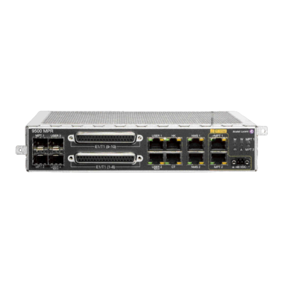
Page 132: Figure 3.44 - Mss-1C Block Diagram
Functional description Figure 3.44 — MSS-1c block diagram (*)Not supported in the current release. (**)Depending on the MSS-1c variant. Figure 3.45 — MSS-1c front view MPR-e and MSS-1c User Manual 3DB19901EFAA Edition 01... -
Page 133: External User Interface
Functional description Figure 3.46 — MSS-1c rear view Note: To use the User Ethernet Ports 3 and 4 an SFP plug-in (electrical or optical) must be installed Note: The meanings of the six LEDs are: • LED M: Major Alarm (red) •... -
Page 134: Traffic 10/100/1000 Base-T Ethernet Interfaces For Data And Service Traffic Via Rj45 Connector
Functional description Note: For 100 Ethernet interface the standard is 100Base-Tx. • 2 SFP ready to accept optical 1000Base-LX/SX SFP or Electrical 1000Base-T SFP • 2x 10/100 Ethernet NMS interfaces for connection of TMN on RJ45 connector • 1 Local Craft terminal interface 10/100 Ethernet allows the straight connection to MPT remote Controller via RJ45 connector •... -
Page 135: Mpt Interface
Functional description • MPR-E: Termination of 10E1 or 16E1 signals (E1 bi-directional interfaces according ITU-T G.703 on the front panel) • MPR-A: Termination of 16T1 signal with MSS-1c 16PDH variant (T1 bi-directional interfaces according to ANSI T1.403/TR 62411 on the front panel) •... -
Page 136: Mss-1C Fan Unit
Functional description The User port 2 can be used as SynchE synchronization. The User port 3 and port 4 can be used as SynchE synchronization in optical mode. Note: MPR-E: User port 3 is not available as a synchronization source on the MSS-1c variant. -
Page 137: Table 3.38 - Mpt Odus That Support An Embedded Diplexer
Functional description The MPT-HC/HC-HQAM/XP/XP-HQAM/9558HC (Microwave Packet Transport) is Microwave Equipment capable of transporting Ethernet traffic over an RF radio channel. For MPR-A, the MPT-HC using the 5.8 GHz channel is referred to as the 9558HC. The MPT-HC/HC-HQAM/XP/XP-HQAM/9558HC includes a waveguide antenna port, one electrical GE interface for data and power, one SFP port for optical Ethernet data, a maintenance connector (with captive protection cap) for RSSI access, and a grounding stud.The 1 GE interface for RPS is not used. -
Page 138: Figure 3.48 - Mpt-Hc Housing (Embedded Diplexer)
Functional description Table 3.38 — (Continued)MPT ODUs that support an embedded diplexer Radio Frequency range MPT-XP Not supported MPT-XP-HQAM Not supported Figure 3.48 shows an MPT-HC with an embedded diplexer. Figure 3.48 — MPT-HC housing (embedded diplexer) Warning: To mount a 6 GHz MPT-HC with internal diplexer in a 1+1 configuration with a MPT-HC with external diplexer, the MPT with internal diplexer must be the Main unit and the MPT with external diplexer must be the Spare unit, see Figure... -
Page 139: Figure 3.49 - Correct Protected Mounting Of 6 Ghz Mpt-Xc With Internal And External Diplexers
Functional description Figure 3.49 — Correct protected mounting of 6 GHz MPT-xC with internal and external diplexers MPR-e and MSS-1c User Manual 3DB19901EFAA Edition 01... -
Page 140: Figure 3.50 - Incorrect Protected Mounting Of 6 Ghz Mpt-Xc With Internal And External
Functional description Figure 3.50 — Incorrect protected mounting of 6 GHz MPT-xC with internal and external diplexers with external diplexer: due to a high number of shifters, the diplexer is external for the flexibility of the shifter customization (5.8, 6, 7, 8, and 10.5 GHz for MPR-E, 5.8, 6, 7, and 8 GHz for MPR-A) where the MPT ODU is composed of two independent units: the external diplexer assembly (containing the diplexer) and the RF transceiver assembly (containing the RF section);... -
Page 141: Table 3.39 - Mpt Odus That Support An External Diplexer
Functional description Table 3.39 — MPT ODUs that support an external diplexer Radio Frequency range MPT-HC 5.8-10.5 GHz MPT-HC-HQAM L6-11 GHz MPT-XP L6-8 GHz MPT-XP-HQAM L6-11GHz Figure 3.51 shows an example of an MPT-HC-HQAM with an external diplexer. Figure 3.51 — View of MPT-HC-HQAM with external diplexer (13-38 GHz) For 5.8 GHz (external diplexer) in MPR-A, the 9558HC polarization is determined by the rotation of the 9558HC (1+0 configuration). -
Page 142: Figure 3.52 - Mpt-Hc V2/Mpt-Xp/9558Hc Housing
Functional description The MPT-HC/HC-HQAM/XP/XP-HQAM/9558HC interface is based on Gigabit Ethernet, that can be either optical or electrical depending on the needs and the cable length. If the optical port must be used (data and/or RPS port), the corresponding SFP plug-in must be installed. -
Page 143: Rssi Monitoring Point
Functional description Figure 3.54 — MPT-HC V2/MPT-XP/9558HC housing (external diplexer) 3.10.3.1 — RSSI monitoring point The RSSI is available on a connector used to manually point the antenna on the field. The higher the voltage, the higher the RSSI and the better aligned the antenna is. The RSL is measured using a is used a voltmeter connected to the MPT with a service kit cable. -
Page 144: Mpt-Mc (Mpr-E)
Functional description Table 3.42 — MPR-A waveguide flange data Waveguid 7 GHz 8 GHz e Type WR13 WR13 WR13 WR11 WR113 WR75 WR62 WR42 WR42 WR28 3.10.4 — MPT-MC (MPR-E) MPT-MC is similar to MPT-HC V2 from architecture standpoint. The only differences are: •... -
Page 145: Power Injector
Functional description Figure 3.55 — MPT-MC housing (internal diplexer) Figure 3.56 — MPT-MC housing (external diplexer) 3.10.5 — Power injector 3.10.5.1 — General MPR-e and MSS-1c User Manual 3DB19901EFAA Edition 01... -
Page 146: Main Functions Of The Power Injector
Functional description The MPT-HC V2/HC-HQAM/MC is powered through an electrical Ethernet cable from the Power Injector. The Power Injector is an indoor device designed to deliver the DC power supply to the MPT-HC/HC-HQAM/MC by using the cable that carries the Ethernet traffic. At the input, the Power Injector receives the Ethernet traffic and the power supply on two dedicated connectors. -
Page 147: Connectors
3.10.6 — MPT Power Unit The MPT Power Unit is an indoor device, which provides power to up to four MPT using coax cable and Type-N connectors. Figure 3.60 — MPT Power Unit 9500 MPR MPT Power Unit Battery MPT1... -
Page 148: Leds
If an MSS-1c is in use, the MPT Extended Power Unit should be installed close to the MSS-1c. An MPT Extended Power Unit is required to power an MPT-XP or MPT-XP-HQAM. Figure 3.61 — MPT extended power unit 9500 MPR MPT Extended Power Unit MPT1 MPT2 VDC Normal +24 or -48V VDC Range -/+19.2 to +57.6V... -
Page 149: Radio Transmission Features With Mpt-Hc/Hc-Hqam/Mc/Xp/Xp-Hqam/9558Hc
Functional description • Two LEDs indicate the presence of DC voltage on each MPT power output. 3.10.8 — Radio transmission features with MPT-HC/HC-HQAM/ MC/XP/XP-HQAM/9558HC 3.10.8.1 — Frequency agility The Frequency Agility feature gives the operator the ability to set the frequency of a single Transceiver within a chosen sub-band to select the RF working channel via MCT. -
Page 150: Power Monitoring
Functional description The capability to adjust the transmitted power in a static and fixed way (RTPC = Remote Transmit Power Control) has been introduced for those countries where, due to internal rules, the ATPC function is not accepted or for those hops in which due to the short length and interface problems, a fixed reduced transmitted power is preferred. -
Page 151: Xpic (With Mpt-Hc/Hc-Hqam/Xp/Xp-Hqam Only, For Mpr-E)
Functional description Figure 3.62 — 1+0 Repeater configuration MPR-e MPR-e Data MSS-4/8 MSS-4/8 MPT Power Unit / MPT Extended Power Unit / Battery 23093 This solution is available with MPT-HC/HC-HQAM/XP/XP-HQAM/9558HC with the following conditions: • Repeater(s) inserted between two terminal MSS-4/8 •... -
Page 152: Figure 3.63 - Co-Channel Xpic
Functional description ; .. Two links are operated on the same radio channel, with one using the vertical polarization and the other using the horizontal polarization. XPIC typically provides a 20-dB improvement in polarization discrimination. The actual improvement will depend on the native discrimination provided at antenna alignment and any reduction of this discrimination caused by atmospheric effects (fading). - Page 153 Functional description 3.10.8.7.1 — MPT-HC/HC-HQAM/XP/XP-HQAM in XPIC with a generic indoor unit XPIC configuration allows a generic indoor unit (e.g. 7705 SAR) to take advantage of both double capacity and hardware redundancy. In fact, the indoor unit can exploit two times the same radio channel doubling the total amount of traffic transported.
-
Page 154: 1+1 Hot Standby For Mpr-E
Functional description Figure 3.64 — Auto TX mute in XPIC configuration 3.10.8.8 — 1+1 Hot StandBy for MPR-e When protection is switched in 1+1 HSB configuration, the spare ODU module is squelched. 3.10.8.8.1 — HSB Switching Criteria The switching criteria are: •... -
Page 155: Link Identifier
Functional description 3.10.8.9 — Link identifier The number of microwave links, especially in urban areas, might cause interference during installation and the turn-up phase. The digital frame incorporates link identity coding capabilities to prevent the capture of an unwanted signal. If a “Link Identifier Mismatch”... -
Page 156: Loopback Activation
Functional description • TDM2TDM and TDM2ETH flows are forwarded back to the MSS-1c or Ethernet generic Device with the source and destination MAC addresses swapped. For TDM2ETH flows, the loopback works only if the ECID Tx and ECID Rx are the same. If the ECID Tx is different from the ECID Rx, the loopback does not work. -
Page 157: Mpr-A: Unlicensed Radio For 9558Hc
(IC) requirements) allow immediate Turn-Up. The 9558HC unlicensed radio can not be upgraded to licensed. Note: Changes or modifications not expressly approved by Alcatel-Lucent could void the authority to operate the JF6-9558HC/6933B-9558HC unlicensed radio. Note: Installation, Turn-Up, Maintenance, and Operation Instruction supplied with the JF6-9558HC/6933B-9558HC unlicensed radio require strict adherence for continued part 15 of the FCC Rules and IC RSS-210 compliance. -
Page 158: Table 3.44 - 5.8 Ghz Unlicensed Antenna Options
Functional description • Adaptive Modulation - automatic interference countermeasures Disadvantages: • Interference from other 5725-5850 ISM band transmissions are possible • Operating restrictions • 5.725 to 5.850 GHz band • Performance could deteriorate due to interference as the frequency band becomes congested. -
Page 159: Mpr-E Standalone Ip Addresses
For transmit power specification, refer to the System Application Rules document, found in the Alcatel-Lucent 9500 MPR-A Engineering Support Documentation. Figure 3.66 — Frequency plan 9558HC: 5.725 to 5.850 GHz unlicensed band (FCC Part 15 and IC RSS-210) 3.10.9 —... -
Page 160: Ne Ip Addresses
The subnet mask is 255.255.255.255 (/32). This mask is fixed and not configurable by the operator. 3.10.9.2 — TMN communication channels On 9500 MPR Network Element the following types of TMN communication channels are present: • In-band TMN through the use of any USER port requiring the activation of a user defined VLAN •... -
Page 161: Sar And Mpr-E Single Ne Ip Addresses
MPR-e follows the 7705 SAR QoS policy and profile. 3.10.11 — MSS-1c traffic profiles Three kinds of traffic profiles have been identified: TDM2TDM (9500 MPR → 9500 MPR, internal to an MPR network) • • TDM2Eth (9500 MPR→ TDM to Ethernet) •... -
Page 162: Figure 3.67 - Traffic Profiles
The E1 or T1 stream is inserted in Terminal 1 and extracted in Terminal 2. One IWF is inside the 9500 MPR, but the second IWF is external to the 9500 MPR network. The Circuit Emulation Service is TDM2ETH in Terminal 1 and Terminal 2. The Cross connections to be implemented are PDH-Radio type in Terminal 1 and Radio- Eth type in Terminal 2. -
Page 163: Tdm2Tdm
4 the Ethernet packets encapsulate the E1 or T1 stream; in case 5 the packets are native Ethernet packets. None of the IWFs belongs to the 9500 MPR network. The Circuit Emulation Service is ETH2ETH in Terminal 1 and Terminal 2. No Cross connections must be implemented. -
Page 164: Figure 3.69 - E1 Traffic In Tdm2Tdm Profile
Bandwidth guaranteed (according to QoS → Highest Queue Priority association) No flooding-autolearning necessary Both the IWFs belong to 9500 MPR and the packets are not supposed to exit the 9500 MPR network. The IWF parameters listed above, have predetermined values and don’t need to be provisioned. -
Page 165: Tdm2Eth
Bandwidth guaranteed (according to QoS Æ Highest Queue Priority association) Destination MAC added before going into whole network (MEF8 compliant) Only one of the IWFs belongs to 9500 MPR and the packets are supposed to exit the 9500 MPR network. -
Page 166: Eth2Eth
E1 or T1 flow) 3.10.11.3 — ETH2ETH None of the IWFs belongs to 9500 MPR. None of the parameters listed in the previous section has to be configured (the 9500 MPR is transparent). Figure 3.71 shows an example using E1 traffic. -
Page 167: Reserved Multicast Addresses
Functional description 3.10.12.2 — Reserved multicast addresses Table 3.45 summarizes the actions taken for specific reserved multicast addresses. Frames identified with these destination addresses are handled uniquely since they are designed for Layer 2 Control Protocols. The actions taken by the system can be: •... -
Page 168: Quality Of Service (Qos)
Addresses (IEEE 802.1ag) 3.10.13 — Quality of service (QoS) The QoS function inside 9500 MPR is the result of a distributed implementation in the MSS-1c switch, if present, and in the MPT. The QoS functions must be properly configured in order to achieve the required behavior on Ethernet flows that will be transmitted. -
Page 169: Table 3.46 - Ieee 802.1P Classification
Functional description For each egress port according to method of QoS classification configured in the switch, the packets are assigned to each queue. 3.10.13.1.1 — TDM flows classification All the TDM traffic flows will be assigned to the highest egress priority queue (Q4). 3.10.13.1.2 —... -
Page 170: Qos In The Mpt
Functional description Deficit Weighted Round Robin (DWRR) is used on the other queues with the following weights: Table 3.48 — DWRR classification QUEUE WEIGHT Q3 (high priority) 3.10.13.1.4 — QoS with jumbo frame While there is no physical limitation to the number of ports that can receive jumbo frame, if to many jumbo flows are transmitted toward the same port into two different queues the QoS could work in wrong way. -
Page 171: Table 3.49 - Qos Based On 802.1P Priority
Functional description Figure 3.74 — QoS in the MPT for MPR-e The QoS feature provides eight internal queues to support different traffic priorities. The QoS function assigns the packet to one of the eight egress transmit queues. • Queue 8 is assigned to TDM2TDM traffic (not used for MPR-e in the current release) •... -
Page 172: Table 3.50 - Qos Based On Diffserv Priority
Functional description Table 3.49 — QoS based on 802.1p priority 802.1p priority Queue 011, 000 010, 001 3.10.13.2.2 — QoS based on DiffServ Table 3.50 — QoS based on DiffServ priority DiffServ priority Queue 111000, 110000, 101110, 101000 Q5 (higher priority) 100110, 100100, 100010, 100000 011110, 011100, 011010, 011000 010110, 010100, 010010, 010000... -
Page 173: Mss-1C Cross-Connections
Functional description Table 3.51 — Default weights Queue Weight 3.10.14 — MSS-1c cross-connections Figure 3.75 — Cross-connection Note: Max #10 or #16 depending on the MSS-1C variant. The cross-connections are realized with a Layer-2 Ethernet Switch inside the MSS-1c. The decision made by the switch to forward the received packet is based on the destination MAC address. -
Page 174: Figure 3.76 - E1/T1 From/To Radio Port
Functional description E1 or T1 can be cross connected to any of the following ports: • Radio port (Figure 3.76) • Ethernet port (Figure 3.77) Each E1 or T1 must be associated to a unique signal flow ID. Figure 3.76 — E1/T1 from/to radio port Figure 3.77 —... -
Page 175: Ethernet Flows
Functional description Note: To configure these cross-connections a connected MPT is needed. 3.10.14.2 — Ethernet flows All flows different from the TDM2TDM and TDM2ETH ones are managed as the standard Ethernet packets: • if 802.1D is enabled, only the destination address is considered to route the packets. •... - Page 176 Functional description • Adaptive clock recovery with or without the node timing: based on the average rate at which the packets (fragments) arrive at Rx site (Adaptive: simpler network, but performances depends on the PDV (Packet Delay Variation) in the Network. Always used when the reference clock isn’t distributed on the whole network).
- Page 177 Functional description A common reference clock is NOT available at both Ends. The IWF system, at Rx side, generates the output clock based on data arrival rate: TDM clock is slowly adjusted to maintain the average fill level of a jitter buffer at its midpoint. 3.10.15.1.3 —...
-
Page 178: Synchronization For Mpr-E Standalone And 7705 Sar
Functional description • SynchE: Any Synchronous Ethernet clock source available at enabled User Ethernet traffic interfaces (both electrical and optical), configured in synchronous operation mode (the User Ethernet ports, SynchE compatible, are given in Ethernet user interface). From ITU-T G.8264 point of view, the MSS is a Synchronous Ethernet equipment equipped with a system clock (NEC). -
Page 179: Table 3.52 - 7705 Sar Pmc Card Mac Addresses
Functional description On the 7705 SAR side, PCR is always turned on automatically when a microwave link is enabled on an MWA RJ-45 port or copper SFP is used. On the MPR-e side, the MPR-e that is connected to the 7705 SAR-8 or 7705 SAR-18 must have PCR enabled and the source and destination MAC addresses of the 7705 SAR-8 or 7705 SAR-18 must be configured as shown in Table 3.52 —... - Page 180 Functional description Table 3.52 — 7705 SAR PMC card MAC addresses SAR slot # PMC port # Source MAC address Destination MAC address 00-80-9F-09-F7-17 00-80-9F-09-F7-07 00-80-9F-09-F7-27 00-80-9F-09-F7-37 00-80-9F-09-F7-47 00-80-9F-09-F8-18 00-80-9F-09-F8-08 00-80-9F-09-F8-28 00-80-9F-09-F8-38 00-80-9F-09-F8-48 00-80-9F-09-F9-19 00-80-9F-09-F9-09 00-80-9F-09-F9-29 00-80-9F-09-F9-39 00-80-9F-09-F9-49 00-80-9F-09-FA-1A 00-80-9F-09-FA-0A 00-80-9F-09-FA-2A 00-80-9F-09-FA-3A 00-80-9F-09-FA-4A...
-
Page 181: Synchronization For Mpr-E In Single Ne Mode With 7705 Sar
Functional description The source and destination MAC addresses can also be summarized by the following formula linked to the slot and port number in HEX: PMC card source MAC address: 00-80-9F-09-F<slot#>-<port#><slot#> PMC card destination MAC address: 00-80-9F-09-F<slot#>-0<slot#> For example, for slot number 4 and port number 2: Source MAC address = 00-80-9F-09-F4-24 Destination MAC address = 00-80-9F-09-F4-04 3.10.15.3 —... -
Page 182: Automatic Link Discovery
5620 SAM to automatically learn the network topology. The radio link discovery is performed via an Alcatel-Lucent proprietary Discovery Protocol. In addition the MPR-e supports automatic link discovery over Ethernet using LLDP. -
Page 183: Lldp On Mpr-E
Automatic link discovery The MPT and the LLDP enabled device advertise their chassis/port IDs and system descriptions along with other information to each other. The devices store the information they learn about each other in local MIB/databases accessible via SNMP. Network management systems discover the network topology by crawling the NEs and querying the MIB on each device. -
Page 184: Snmp Mib Management
Automatic link discovery • lldpV2NotificationInterval = 30 • lldpV2TxCreditMax = 5 (txCreditMax) • lldpv2MessageFastTx = 1 (msgFastTx) • lldpV2TxFastInit = 4 (txFastInit) The LLDP agent is configured to advertise the NE's public IP address as the local management address. The operator cannot modify this configuration. If LLDP is activated on the User Ethernet interface, it is enabled for transmission and reception LLDPDUs (Transmit only and Receive only modes are not supported). -
Page 185: Notifying The Snmp Manager
Automatic link discovery If the neighbor is unknown, that is, no entry exists in the remote systems MIB for that neighbor, the MPR-e creates it. If the neighbor is known, the MPR-e uses the new information contained in the LLDPDU to replace the existing entry in the MIB. -
Page 186: Displaying Neighbors In The Mct
Automatic link discovery Figure 3.79 provides an example where Alcatel-Lucent’s radio Discovery Protocol and Ethernet user interface LLDP can be used. Figure 3.79 — Radio discovery protocol and Ethernet user interface LLDP 3.11.5.2 — Displaying Neighbors in the MCT The MPR-e’s radio and Ethernet interface neighbors are visible in the MCT, see Neighbors for MPR-e. -
Page 187: Ne Management By Software Application
4 — NE management by software application 4.1 — Security session management The MCT will close automatically after 30 minutes of session inactivity. This is not applicable in the following cases: • When the 15 minutes or 24 hours Performance Monitoring is activated (Normalized, Adaptive or QoS Ethernet) •... -
Page 188: Webeml Start
WebEML start Figure 4.2 — Connection lost message 4.2 — WebEML start This chapter explains all the screens of the WebEML (JUSM/CT), which is started by a double click on the WebEML icon on the PC desktop. The WebEML must be connected to the CT port of the MSS-1c or to the MPR-e Ethernet generic device as explained in the Provisioning chapter. -
Page 189: Figure 4.4 - Neto Servers Manager
WebEML start Figure 4.4 — NEtO Servers Manager Click on the FTP Server or SFTP Server button to start the FTP server. The Server LED will turn green. In the example shown in Figure 4.4, three RMI Resources are detected by the NEtO Servers Manager. -
Page 190: Figure 4.6 - Neto Main View With Supervised Ne
WebEML start Note: For MSS-1c, to access the NE the PC must be configured to “Get automatically an IP address” (DHCP server) and a static route must be added using the command “route add 10.0.1.2 mask 255.255.255.255 192.168.30.1”. If the NE IP address cannot be retrieved, it is possible to use the local IP address of the CT port of the MSS-1c. -
Page 191: Figure 4.7 - Consent Banner
WebEML start Figure 4.7 — Consent banner An MPT Craft Terminal (MCT) window opens; see Figure 4.8. Figure 4.8 — MCT Screen If no user account is configured, log in as one of the following: Default Administrator: username Default_Admin, password 9500MPR_alu Default Craft Person: username Default_Craft, password 9500MPR_craft Click on the Login button to open the MCT main view. -
Page 192: Figure 4.9 - Main View: System Overview For Mpr-E
WebEML start Figure 4.9 — Main view: system overview for MPR-e Tab panels User Account Domain alarm type synthesis Tool bar Alarm Synthesis Navigator General information IP address of the connected NE 23701 MPR-e and MSS-1c User Manual 3DB19901EFAA Edition 01... -
Page 193: Figure 4.10 - Main View: System Overview For Mss-1C
WebEML start Figure 4.10 — Main view: system overview for MSS-1c Domain alarm Tab panels User Account synthesis type Tool bar Alarm Synthesis Navigator General information IP address of the connected NE 23700 Figure 4.11 shows the banner that is displayed for the craft user. The Administration tab and Administrative functions are not available for the craft user. -
Page 194: 7705 Sar And Mpr-E In Single Ne: Mct Launcher Start
4.3 — 7705 SAR and MPR-e in Single NE: MCT Launcher start In 9500 MPR R4.1.0, the MCT Launcher is the application that interfaces with the 7705 SAR to show the microwave configuration of the system. This application is the entry point for accessing each individual MPR-e connected to a 7705 SAR in Single NE mode. -
Page 195: Figure 4.13 - Mct Launcher Icon
7705 SAR and MPR-e in Single NE: MCT Launcher start To start the MCT Launcher, double-click on the MctLauncher icon on the PC desktop. The MCT Launcher window opens. Figure 4.13 — MCT Launcher icon Enter the IP address of the 7705 SAR along with the 7705 SAR username and password (default is admin admin for both username and password) and click on the Finish button. -
Page 196: Figure 4.15 - Mct Launcher Main Screen
7705 SAR and MPR-e in Single NE: MCT Launcher start Figure 4.15 — MCT Launcher main screen Click on the green triangle or double click on one valid line in the list to open the MCT System overview. Figure 4.16 — MCT system overview with 7705 SAR The MCT Tool bar has the following buttons: •... -
Page 197: Mct Tool Bar
MCT tool bar The MCT Launcher reports the complete list of MPR-e configured in the 7705 SAR CLI, reflecting their operative status. In a table format, the radio screen shows all MPR-e information inherited according to the mw-link object (configured in CLI) they belong to. Information for MPR-e units that are operative up appears in black in the list. -
Page 198: Domain Alarm Synthesis Area
Domain alarm synthesis area • Red: Critical alarm (CRI) • Orange: Major alarm (MAJ) • Yellow: Minor alarm (MIN) • Cyan: Warning alarm (WAR) • Blue: Indeterminate (IND) The meaning of each icon in the Alarm Synthesis is: • CRI - Critical alarm Synthesis of alarms that need immediate troubleshooting (typical: NE isolation) •... -
Page 199: General Information On The Management State
General information on the management state 4.7 — General information on the management state The different management states concerning the NE are shown in two tab-panels: • Radio Synthesis Figure 4.18 — Radio synthesis tab • Radio Synthesis with XPIC configured (only with MPT-HC/HC-HQAM/XP/ XP-HQAM/9558HC in MPR-e configuration) Figure 4.19 —... -
Page 200: My Account
My account The Network Supervision gives information on the: • Local Access state: indicates whether the NE is managed by a craft terminal or by the • OS Supervision state: indicates whether the communication with the OS is established 4.8 — My account The My Account menu can be used by the Craft or Administrator user to change the user’s own password. -
Page 201: Figure 4.22 - Change Password Window
My account • The Change Password window opens, see Figure 4.22. Enter your current password and enter the new one twice. Figure 4.22 — Change password window • The password must meet the rules that are displayed on the Change Password window. -
Page 202: Navigator Area
Navigator area • If the password change fails, an error window opens; see Figure 4.25. Figure 4.25 — Password change failure 4.9 — Navigator area The Navigator panel displays different options depending on the selected function in the upper tabs. The following tabs are available: Commissioning •... -
Page 203: Commissioning
Navigator area • Normalized • Adaptive modulation • Ethernet QoS • RSL history • Traffic port Ethernet for MPR-e • Monitoring Troubleshooting • Inventory • Troubleshooting • Monitoring Maintenance • Inventory • Backup/restore • Software download • Configuration > Radio •... -
Page 204: Inventory
Navigator area • Monitoring Note: Not all options are applicable for MPR-e in Single NE mode with 7705 SAR configuration. 4.9.1.1 — Inventory The inventory tab displays all the inventory data of the NE, see Figure 4.26. Figure 4.26 — Inventory 4.9.1.2 —... -
Page 205: Figure 4.27 - Software Download Using Ftp
Navigator area • get a summary of the specific software versions on the Stand-by bank (Stand-by Software Package Summary tab) Note: Software rollback is not supported. 4.9.1.2.1 — Software package versions tab Software Download can be completed using the FTP or SFTP server. The FTP server is chosen by default, see Figure 4.27. -
Page 206: Figure 4.28 - Software Download Using Sftp
Navigator area Figure 4.28 — Software download using SFTP Warning: An FTP Server must be installed on the PC containing the Software Package. The PC's firewall (Microsoft's default firewall) may prevent the download from starting up. The Apache Server, installed with the WebEML from the TCO Software Suite R5.2 DVD- ROM, is started with NEtO as the default FTP/SFTP server. -
Page 207: Figure 4.29 - Sftp Fingerprint Window
Navigator area Click on the Reset to Default button to recall the default connection settings if an error is made. Click on the Check button. If trouble occurs, check the NEtO Servers Manager window to verify that the FTP/SFTP Server is on. If the fingerprint is not filled in manually, the MCT displays the fingerprint in a popup for confirmation, see Figure... -
Page 208: Figure 4.30 - Directory For The Sw Component If Apache Server Is In Use
Navigator area Figure 4.30 — Directory for the SW component if Apache server is in use Put a check mark on the Forced check box to download the complete file without any comparison between the file already present in the stand-by bank and the new file to be downloaded. -
Page 209: Figure 4.31 - Software Download: Active Software Package Summary
Navigator area Figure 4.31 — Software download: Active Software Package Summary 4.9.1.2.3 — Standby Software Package Summary tab The Standby Software Package Summary tab shows the versions of the programmable different components of the stand-by bank. MPR-e and MSS-1c User Manual 3DB19901EFAA Edition 01... -
Page 210: Software Download For Mpr-E Standalone
Navigator area Figure 4.32 — Software download: Stand-by software package summary 4.9.1.3 — Software download for MPR-e standalone This menu must be used to download a new software version on the NE (Software Package Versions tab) or to get a summary of the specific software versions on the programmable different components on the Active bank (Active Software Package Summary tab) or on the Stand-by bank (Stand-by Software Package Summary tab). -
Page 211: Figure 4.33 - Software Download Using Ftp
Navigator area Figure 4.33 — Software download using FTP Figure 4.34 — Software download using SFTP MPR-e and MSS-1c User Manual 3DB19901EFAA Edition 01... -
Page 212: Figure 4.35 - Sftp Fingerprint Window
Navigator area Warning: An FTP Server must be installed on the PC containing the Software Package. The PC's firewall (Microsoft's default firewall) may prevent the download from starting up. The Apache Server, installed with the WebEML from the TCO Software Suite R5.2 DVD- ROM, is started with NEtO as the default FTP/SFTP server. -
Page 213: Figure 4.36 - Directory For The Sw Component If Apache Server Is In Use
Navigator area Click on the OK button to continue. In the Software Package field, select the file descriptor (previously copied to the PC). When the Apache FTP server (embedded in the TCO SW Suite) is used, it is mandatory to copy the SWP component to the FTP root directory: “\Document and Settings\<login name>\9500MPR-E\res\home”. -
Page 214: Figure 4.37 - Software Download
Navigator area The WebEML must be relaunched. Figure 4.37 — Software download 4.9.1.3.2 — Active Software Package Summary tab The Active Software Package tab shows the versions of the programmable different components of the active bank. MPR-e and MSS-1c User Manual 3DB19901EFAA Edition 01... -
Page 215: Figure 4.38 - Software Download: Active Software Package Summary
Navigator area Figure 4.38 — Software download: Active Software Package Summary 4.9.1.3.3 — Standby Software Package Summary tab The Standby Software Package Summary tab shows the versions of the programmable different components of the stand-by bank. MPR-e and MSS-1c User Manual 3DB19901EFAA Edition 01... -
Page 216: Configuration
Navigator area Figure 4.39 — Software download: Stand-by software package summary 4.9.1.4 — Configuration 4.9.1.4.1 — Date/time The NE Date/Time screen displays the current NE time and the current computer time, see Figure 4.40. To re-align the NE time with the computer time, click on the Synchronize NE with Computer button and click on the Refresh button. -
Page 217: Figure 4.40 - Date/Time Configuration
Navigator area Figure 4.40 — Date/time configuration This menu is not applicable in Single NE mode with 7705 SAR configuration. 4.9.1.4.2 — Site information This menu has to be used to enter the optional information to identify the site (Site Name and Site Location), see Figure 4.41. -
Page 218: Figure 4.41 - Site Information
Navigator area Figure 4.41 — Site information This menu is not applicable for an MPR-e in Single NE mode with 7705 SAR configuration. 4.9.1.4.3 — MSS-1c Protection Select the 1+0 protection scheme and Apply, see Figure 4.42. MPR-e and MSS-1c User Manual 3DB19901EFAA Edition 01... -
Page 219: Figure 4.42 - Protection Configuration
Navigator area 4.9.1.4.3.1 — 1+0 configuration Figure 4.42 — Protection configuration 4.9.1.4.4 — MPR-e Radio scheme configuration For MPR-e standalone, the protection scheme must be explicitly selected as 1+0. When the MPR-e is in Single NE mode with 7705 SAR, the protection scheme is ruled by the 7705 SAR according to mw-link configuration in the CLI. -
Page 220: Figure 4.43 - 1+0 Protection Configuration
4.9.1.4.4.2 — 1+1 HSB configuration in Single NE mode with 7705 SAR In 9500 MPR Release 4.1.0, when 1+1 HSB is selected, the screen reports the status of the EPS, TPS and RPS protection. This screen reports only the current status and configuration: it cannot be used to make configuration changes. -
Page 221: Figure 4.44 - 1+1 Hsb Configuration
Navigator area Figure 4.44 — 1+1 HSB configuration 4.9.1.4.5 — User Port for MPR-e This menu allows the operator to synchronize the MPR-e. As described in Synchronization for MPR-e in Single NE mode with 7705 SAR, when MPR-e is in Single NE mode with 7705 SAR, synchronization is self detected and configured. -
Page 222: Figure 4.45 - User Port Menu
Navigator area Figure 4.45 — User port menu Depending on the connectivity type used between the MPT and the Ethernet Generic device, the synchronization capabilities will be different. The following connectivity types can be provisioned: • Optical • Electrical 100 Mb/s •... -
Page 223: Figure 4.46 - Optical Ge Active Configuration With Synce Synchronization
Navigator area Figure 4.46 — Optical GE active configuration with SyncE synchronization Figure 4.47 — Optical GE active configuration with Internal Oscillator MPR-e and MSS-1c User Manual 3DB19901EFAA Edition 01... -
Page 224: Figure 4.48 - Electrical 100 Mb/S Active Configuration With Synce Synchronization
Navigator area Figure 4.48 — Electrical 100 Mb/s active configuration with SyncE synchronization In Electrical 100 Mb/s configuration, the synchronization is bidirectional only. MPR-e and MSS-1c User Manual 3DB19901EFAA Edition 01... -
Page 225: Figure 4.49 - Electrical 100 Mb/S Active Configuration With Internal Oscillator
Navigator area Figure 4.49 — Electrical 100 Mb/s active configuration with Internal Oscillator MPR-e and MSS-1c User Manual 3DB19901EFAA Edition 01... -
Page 226: Figure 4.50 - Electrical 1 Gb/S Active Configuration With Automatic Synce Synchronization
Navigator area Figure 4.50 — Electrical 1 Gb/s active configuration with automatic SyncE synchronization (green LED) The green LED indicates that the autonegotiation process is completed. MPR-e and MSS-1c User Manual 3DB19901EFAA Edition 01... -
Page 227: Led)
Navigator area Figure 4.51 — Electrical 1 Gb/s active configuration with automatic SyncE synchronization (red LED) The red LED indicates that the autonegotiation process failed or the link is down. MPR-e and MSS-1c User Manual 3DB19901EFAA Edition 01... -
Page 228: Figure 4.52 - Electrical 1 Gb/S Active Configuration With Manual Synce Synchronization
Navigator area Figure 4.52 — Electrical 1 Gb/s active configuration with manual SyncE synchronization (SyncE IN or SyncE OUT) MPR-e and MSS-1c User Manual 3DB19901EFAA Edition 01... -
Page 229: Figure 4.53 - Electrical 1Gb/S Active Configuration With Pcr Synchronization
Navigator area Figure 4.53 — Electrical 1Gb/s active configuration with PCR synchronization If PCR has been selected, the Source MAC Address and the Destination MAC Address must be entered. Note: Synchronization must be provisioned for PCR between the MPR-e standalone and a PMC port on the 7705 SAR. -
Page 230: Figure 4.54 - Electrical 1 Gb/S Active Configuration With Internal Oscillator
Navigator area Figure 4.54 — Electrical 1 Gb/s active configuration with Internal Oscillator 4.9.1.4.6 — Radio To configure the radio, perform the following in the Radio Configuration tab: Telecommunications standard panel: Select the ETSI or ANSI market. Modulation panel: The operation mode can be with Fixed Modulation (FCM) or with the Adaptive Modulation (ACM). - Page 231 Navigator area Select the Modem Profile Option: Current Mask Standard Profile or New Mask Standard Profile MPR-E: Current mask standard profile or New mask standard profile MPR-A: Choose Standard Profile In the Reference Modulation field, select the Modulation scheme: MPR-E: up to 256 QAM for MPT-HC V2, MPT-MC, and MPT-XP up to 1024QAM for MPT-HC-HQAM (if the compatibility with MPT- HC box is unchecked)
-
Page 232: Figure 4.55 - Warning Screen
Warning: If the changes increase the current radio bandwidth, the warning message (Figure 4.55) will be raised to the operator. The new setting must be validated with Alcatel-Lucent. Figure 4.55 — Warning screen Frequency The system can operate with different types of ODUs according to the RF band and to the channel arrangement. - Page 233 Navigator area You can modify only the Tx power relevant to the lowest modulation scheme. In this field you must enter the constant power, which will be used with the lowest modulation. Note: The same power value will be used by the other modulation schemes. ATPC settings •...
-
Page 234: Figure 4.56 - Radio Configuration Mpt-Hc-Hqam: Fcm - Rtpc
Navigator area Figure 4.56 — Radio configuration MPT-HC-HQAM: FCM - RTPC In this example the MPT-HC compatibility is enabled. MPR-e and MSS-1c User Manual 3DB19901EFAA Edition 01... -
Page 235: Figure 4.57 - Radio Configuration Mpt-Hc-Hqam: Fcm - Atpc
Navigator area Figure 4.57 — Radio configuration MPT-HC-HQAM: FCM - ATPC In this example the MPT-HC compatibility is enabled. MPR-e and MSS-1c User Manual 3DB19901EFAA Edition 01... -
Page 236: Figure 4.58 - Radio Configuration Mpt-Hc-Hqam: Acm - Rtpc
Navigator area Figure 4.58 — Radio configuration MPT-HC-HQAM: ACM - RTPC In this example MPT-HC compatibility is disabled, offering modulation schemes up to 1024QAM. All modulations from QPSK up to 1024QAM are available. MPR-e and MSS-1c User Manual 3DB19901EFAA Edition 01... -
Page 237: Figure 4.59 - Radio Configuration Mpt-Hc Hqam: Acm - Atpc
Navigator area Figure 4.59 — Radio configuration MPT-HC HQAM: ACM - ATPC In this example MPT-HC compatibility is disabled, offering modulation schemes up to 1024QAM. All modulations from QPSK up to 1024QAM are available. XPIC (only for MPR-e with MPT-HC/HC-HQAM/XP/XP-HQAM) The XPIC can be configured for an MPT-HC V2/MPT-XP (with the RPS + XPIC external module) and for MPT-HC-HQAM/XP-HQAM (with embedded XPIC functions). -
Page 238: Figure 4.60 - Xpic Configuration (Mpt-Hc-Hqam)
Navigator area Figure 4.60 — XPIC configuration (MPT-HC-HQAM) When the XPIC has been configured, the MPT-HC/HC-HQAM/XP/XP-HQAM will appear in the System Overview screen (see Figure 4.61). MPR-e and MSS-1c User Manual 3DB19901EFAA Edition 01... -
Page 239: Figure 4.61 - Xpic With Horizontal Polarization System Overview
Navigator area Figure 4.61 — XPIC with horizontal polarization system overview When the XPIC has been configured in the Radio Synthesis tab the XPD value is shown (see Figure 4.62). Figure 4.62 — XPD Warning: When you change a radio parameter (such as modulation mode ACM/FCM, modulation/capacity, Tx or Rx freq or shifter value), a warning message is raised (see Figure 4.63). -
Page 240: Figure 4.63 - Warning Message
Navigator area Figure 4.63 — Warning message 4.9.1.4.7 — Advanced Radio Figure 4.64 — Advanced radio configuration This menu is used to specify the expected and sent identifier values of parameters related to the link management and, if necessary, to modify them. If the link identifier is Enabled, the following fields can be filled in: •... - Page 241 4.9.1.4.8 — Radio encryption (available only for MPT-HC/HC-HQAM) The 9500 MPR supports 256bit AES encryption with static key. A key generation string (Passphrase) has to be entered at both ends of the radio link to generate the encryption/ decryption key.
-
Page 242: Figure 4.65 - Radio Encryption
Navigator area Figure 4.65 — Radio encryption After entering the access password, you are invited to enter a passphrase of your choice that will be used to generate the encryption key before being able to activate the encryption, see Figure 4.66 Figure 4.67. -
Page 243: Figure 4.66 - Set Radio Encryption Passphrase
Navigator area Figure 4.66 — Set radio encryption passphrase Figure 4.67 — Set passphrase window The passphrase must be set twice with a length between 20 and 32 characters. It is possible, for convenience, to copy and paste the passphrase from a text file to the MCT fields. However, it is not authorized to copy the content of an MCT passphrase field and paste it elsewhere. -
Page 244: Figure 4.68 - Radio Encryption Set
Navigator area Figure 4.68 — Radio encryption set 4.9.1.4.9 — MSS-1c provisioning This menu gives access to MSS-1c provisioning: MPR-e and MSS-1c User Manual 3DB19901EFAA Edition 01... -
Page 245: Figure 4.69 - Mss-1C
Navigator area Figure 4.69 — MSS-1c The menu offers the following operations: Figure 4.70 — Provisioning Management menu When the MCT is launched the MSS-1c configuration data is read from the NE and the navigator shows all the MSS-1c provisioning sub-menus. If trouble occurs, verify that the FTP Server in the NEtO Servers Manager window is on. -
Page 246: Figure 4.71 - Provisioning Sub-Menus
Navigator area Figure 4.71 — Provisioning sub-menus To change the MSS-1c configuration, modify the parameters (see Ethernet port provisioning Per flow policer), then push the Apply button to send and execute the modifications on the NE. Warning: the modification of some parameters will cause a restart of the NE after the Apply action. -
Page 247: Table 4.1 - Parameters Leading To A Restart
Navigator area Note: When the MCT is launched from the 1353OMS, the management of the configuration of the MSS-1c is done through a provisioning file that has to be uploaded/downloaded from/to the NE with a FTP server. The first screen of the MSS-1c provisioning invites the User to do this operation and offers different provisioning modes: "Initial configuration"... -
Page 248: Figure 4.72 - Cancel Button
Navigator area Table 4.1 — Parameters leading to a restart Disabling the TMN in Band Modifying the User port configuration (UNI / NNI) Modifying the S-TPID in 802.1ad bridge mode A tooltip is also displayed when the mouse cursor is placed over the icon. If one or several parameters are changed, the operator is also warned when he pushes the Apply button. -
Page 249: Figure 4.73 - Refresh Button
Navigator area Figure 4.73 — Refresh button 4.9.1.4.9.1.2 — B) Conversions In the conversion situations described in this section, the Navigator shows only this entry: that is without sub-menus displayed. When the button Refresh is pressed, the messages shown hereafter will be displayed. •... - Page 250 Navigator area If the operator cancels the conversion, this message is displayed, the loading and conversion are stopped and the data displayed in the MSS-1c screens are unmodified. • Both conversions may be applied on the same file, one after the other. This is the case when the file has been saved with a MSS-1c 10E1 on another NE.
-
Page 251: Figure 4.74 - Ethernet Ports Provisioning
Navigator area 4.9.1.4.9.2 — Ethernet port provisioning Figure 4.74 — Ethernet ports provisioning 4.9.1.4.9.2.1 — A) MPT connection MPT connected through: select the right port where the MPT is connected to MSS-1c. This information is used to configure the radio ports used in cross connections (TDM and VLANs). - Page 252 Navigator area Note: Forced mode setting is not recommended for a definitive configuration. Autonegotiation should be chosen. • If Auto negotiation is selected, for Speed select one or several check boxes, the same for duplex mode • If Auto negotiation is not selected, for Speed select only one value, the same for duplex mode.
- Page 253 Navigator area 4.9.1.4.9.3 — PDH ports and local IWF cross connection provisioning For the explanation of the traffic profiles TDM2TDM and TDM2ETH (see MSS-1c traffic profiles). Note: The 75 ohm unbalanced impedance with BNC or 1.6/5.6 connectors. The 120 ohm balanced impedance with other connectors.
-
Page 254: Figure 4.75 - Cross Connection Tdm2Tdm (E1 Case)
Navigator area Figure 4.75 — Cross connection TDM2TDM (E1 case) The “One shot tributaries configuration” is also available to configure all the tributaries in one shot as shown in Figure 4.76. Note: If the One shot tributary configuration is not fully displayed, check that you have selected the classic window setting, if you are using Windows 7. -
Page 255: Figure 4.76 - One Shot Tributaries Provisioning
Navigator area Figure 4.76 — One shot tributaries provisioning Figure 4.77 shows the different elements involved in the cross connection, in green the PDH part and CES part (encapsulation in Ethernet frame done by IWF), in blue the Ethernet part realized by the switch. Figure 4.77 —... -
Page 256: Figure 4.78 - Cross Connection Tdm2Tdm (T1 Case)
Navigator area 4.9.1.4.9.3.2 — B) TDM2TDM cross connection (T1 case) To configure a TDM2TDM cross connection: • Select the Port configuration: T1 • Choose the T1 port you want to configure (between 1 and 16) • In the column Enabled: Check the box •... - Page 257 Navigator area 4.9.1.4.9.3.3 — C) TDM2ETH cross connection (E1 case) To configure a TDM2ETH cross connection: • Configure the E1 port Impedance (75 or 120 Ohms). This choice is for all the ports. • Choose the E1 port you want to configure (between 1 and 10 on MSS-1c or 1 and 16 on MSS-1c 16PDH) •...
-
Page 258: Figure 4.79 - Cross Connection To User Ethernet Port
Navigator area See T1-2 in the Figure 4.78 4.9.1.4.9.3.5 — E) Cross connection to user Ethernet port Figure 4.79 — Cross connection to user Ethernet port Note: In case of the "One shot tributary configuration" is not fully displayed, check that you have selected "classic window"... -
Page 259: Figure 4.80 - Cross Connection Functional Scheme
Navigator area The following picture represents the different elements involved in the cross connection, in green the PDH part and CES part (encapsulation in Ethernet frame done by IWF), in blue the Ethernet part realized by the switch. Figure 4.80 — Cross connection functional scheme MPR-e and MSS-1c User Manual 3DB19901EFAA Edition 01... -
Page 260: Figure 4.81 - Management Port Provisioning
Navigator area 4.9.1.4.9.4 — Management port provisioning Figure 4.81 — Management port provisioning 4.9.1.4.9.4.1 — A) NMS1 & NMS2 To configure the NMS1 and NMS2 ports, in the relevant area: • Port Enabled: check the box • Auto negotiation: • check the box: the port will negotiate speed and duplex mode with its peer •... -
Page 261: Figure 4.82 - Tdm Cross Connection Between Radio And Ethernet Port
Navigator area 4.9.1.4.9.4.2 — B) In-band TMN on one user ethernet port provisioning To configure the TMN In-band: • Enabled: Check the box • Port number: Select one port in the list (only available in 802.1Q and 802.1ad bridge mode). •... -
Page 262: Figure 4.83 - Cross Connection Functional Scheme
Navigator area To configure a TDM cross connection between radio and Ethernet port: • Push button Add cross-connection and fill the fields. • In column User port: Select a port in the list • In column Flow Id: Enter a valid VLAN Id (between 2 and 4080). This VLAN Id must be equal to the one used to encapsulate PDH flows at the transmitter side •... -
Page 263: Figure 4.84 - Network Synchronization Clock Provisioning
Navigator area 4.9.1.4.9.6 — Network synchronization clock provisioning Figure 4.84 — Network synchronization clock provisioning Note: Only the ports (ETH and PDH) previously defined are available to support the synchronization. To configure the network synchronization: • Synchronization role, select in the list: •... -
Page 264: Figure 4.85 - Ne Bridge Mode Selection
Navigator area 4.9.1.4.9.7 — Bridge provisioning (create a user virtual LAN) In the NE bridge mode field select in the list: • 802.1D: default switch configuration, MAC learning based switching • 802.1Q: switch mode with Virtual Customer LAN. Switching is based on MAC and C-VLAN •... - Page 265 Navigator area • In the column VLAN Name: Enter a name • In the columns User 1 to 4: Check the box if the port is implied in the VLAN. Both enabled and disabled ports can be member of a VLAN. Note that radio port is automatically included.
-
Page 266: Figure 4.86 - Ne Bridge Mode Selection
Navigator area Figure 4.86 — NE bridge mode selection To create a Service VLAN: • Push the button Add VLAN and fill the fields • In column VLAN Id: Enter a valid VLAN Id (from 2 to 4080) and not used in another VLAN or cross connection •... -
Page 267: Figure 4.87 - Port Vlan Provisioning
Navigator area 4.9.1.4.9.8 — Port VLAN Provisioning This screen can be filled only if the 802.1Q or 802.1ad bridge modes have been selected in Bridge configuration screen. 4.9.1.4.9.8.1 — A) In 802.1Q mode To configure the behavior of each user port you can: •... -
Page 268: Figure 4.88 - Port Vlan Provisioning
Navigator area 4.9.1.4.9.8.2 — B) In 802.1ad (Q in Q) mode If the port is configured in NNI, no choice is offered to the operator (“Admit tagged frames only” is automatically selected). If the port is configured in UNI “Admit all frames” (untagged and C-Tagged frames are admitted) is automatically selected, then the S-VLAN associated to this UNI port is displayed and cannot be changed. -
Page 269: Figure 4.89 - Storm Control And Rate Limiting
Navigator area Per port rate limiting, for each user port, in ingress and egress, rate limit and burst size may be set. Note: Per port rate limiting: minimum burst size at egress is 114 kBytes. So the burst size limitation will become accurate for bust size limitation set over 2500 kBytes. Storm Control thresholds are not guaranteed when total rate at ingress is higher than 1 GPSs. -
Page 270: Figure 4.90 - Per Flow Policer
Navigator area Note: In 802.1Q Bridge mode, VLAN 1 cannot be selected. For burst size setting over 8000 bytes, the accuracy of the limitation is not guaranteed. The flows without flow policer rule are not guaranteed (Yellow frames). Default values are proposed. They can be changed by the operator in the authorized range. Figure 4.90 —... -
Page 271: Figure 4.91 - Ethernet Traffic Qos
Navigator area Figure 4.91 — Ethernet traffic QoS QoS classification Two methods can be selected: • IEEE 802.1p • DiffServ IEEE 802.1p MPR-e and MSS-1c User Manual 3DB19901EFAA Edition 01... -
Page 272: Figure 4.92 - Ieee 802.1P
Navigator area Figure 4.92 — IEEE 802.1p Select the appropriate check boxes for each priority (0 to 7) to be assigned to a specific egress queue (queue 1 to 5). Note: Queue 5 is the highest-priority queue; queue 1 is the lowest-priority queue. You can click on the Default button to restore the default classification. -
Page 273: Figure 4.93 - Diffserv
Navigator area Figure 4.93 — DiffServ A specific range of DiffServ Code Points can be assigned to a specific egress queue (queue 1 to queue 5). Note: Queue 5 is the highest-priority queue, queue 1 is the lowest-priority queue. You can click on the Default button to restore the default classifications. Click on the Add button to add a range that can be assigned to a specific queue. -
Page 274: Figure 4.94 - Ethertype Classification
Navigator area Figure 4.94 — EtherType classification Scheduling algorithms Figure 4.95 — Scheduling algorithms MPR-e and MSS-1c User Manual 3DB19901EFAA Edition 01... -
Page 275: Figure 4.96 - Cross-Connection Creation
Navigator area This menu allows to change the scheduler operation. Note: The scheduling mode refers only to queue 1 to 5, because for queue 6 to 8 the scheduling mode is fixed to HQP. The scheduling mode can be DWRR or HQP. If DWRR has been selected the DWRR weight can be assigned to a specific egress queue (queue 1 to queue 5). -
Page 276: Figure 4.97 - Tdm2Eth Cross-Connection
Navigator area To manage the cross-connections, select one of the following buttons: • Add new cross-connection • Clone cross-connection • Modify selected cross-connection • Remove cross-connection To create the TDM2ETH cross-connection: Click the Add new cross-connection button Enter the VLAN ID Enter the MAC address of the destination IWF Enter the clock source: Differential or Adaptive Click on the Add button... -
Page 277: Figure 4.98 - Cross-Connection Modify
Navigator area • cloned by pressing Clone cross-connection button to create another cross- connection by modifying the parameters and then pressing the Add clone button (Figure 4.99) Figure 4.98 — Cross-connection modify MPR-e and MSS-1c User Manual 3DB19901EFAA Edition 01... -
Page 278: Figure 4.99 - Cross-Connection Clone
Navigator area Figure 4.99 — Cross-connection clone This menu is not applicable in Single NE mode with 7705 SAR configuration. In Single NE mode with 7705 SAR, cross-connections are set up as part of configuration of the 7705 SAR. 4.9.1.4.12 — Networking This menu must be used to assign (or to show) the networking configuration of the NE. -
Page 279: Figure 4.100 - Network Interfaces
Navigator area 4.9.1.4.12.1 — Network interfaces Figure 4.100 — Network interfaces • Network element field This IP address is the local IP address of the NE. Warning: The change of this address will close the connection with the MCT and cause a traffic impact. -
Page 280: Figure 4.101 - Tmn Rf Field
Navigator area Figure 4.101 — TMN RF field Note: The TMN RF in-band Van ID must be different from the one configured for User Ethernet TMN in-band. You need to ensure the consistency of the TMN RF configuration at both ends of the radio interface, otherwise the TMN RF in-band link will not set up. -
Page 281: Figure 4.102 - Areas
Navigator area Warning: For MSS-1c, If the TMN In-band is not enabled in the Provisioning Tool, it is not possible to enable the TMN In-band using the WebEML. Caution: For MPR-e, changes to these parameters will cause the connection with the MPT to be dropped. -
Page 282: Figure 4.104 - Configuration Message
Navigator area Figure 4.104 — Configuration message Note: When the 9500 MPR is used in MPR-e configuration with other equipment, the OSPF interface parameters of the equipment must be the same as those of the related TMN interface on the 9500 MPR. -
Page 283: Figure 4.107 - Areas
Navigator area Figure 4.107 — Areas Change the Area Type. Click on the Modify button. Figure 4.108 — Modify OSPF Area • To attach an interface to an OSPF Area Figure 4.109 — Interfaces Select an OSPF Area in which the interface has to be added. Click on the Attach button. -
Page 284: Figure 4.110 - Network Interfaces Attachment To An Ospf Area
Navigator area Figure 4.110 — Network interfaces attachment to an OSPF Area • To detach an interface Figure 4.111 — Interfaces Select None. Click on the Detach button. Figure 4.112 — Network interfaces attachment to an OSPF Area 4.9.1.4.12.2 — Static routing The Static Routing menu is used to configure the parameters for IP Static Routing Configuration, see Figure... -
Page 285: Figure 4.113 - Static Routing
Navigator area • Next Hop: the User can select Point to Point Link to address the link on the radio side or Gateway IP to define the address of a gateway reachable on the TMN In-band interface. Figure 4.113 — Static routing The Add button inserts a new Static Routing Table row above the selected row. -
Page 286: Figure 4.114 - Routing Table
Navigator area Figure 4.114 — Routing table Note: Click on the Refresh button to display the latest changes. 4.9.1.4.12.4 — Trusted SNMP Managers A Trusted manager is an SNMP manager to which the NE automatically sends the traps generated inside the NE. See Figure 4.115. -
Page 287: Figure 4.115 - Trusted Snmp Managers
Navigator area Figure 4.115 — Trusted SNMP Managers To activate a Trusted Manager, enter the IP Address of the SNMP manager, the Traps UDP Port and the Manager Type (Network Manager Layer or Equipment Manager Layer), then click on the Register button. Note about the Manager Type: •... -
Page 288: Figure 4.116 - Manager Registration
Navigator area Figure 4.116 — Manager registration To delete a Manager select the Manager from the list and click on the Unregister button. 4.9.1.4.13 — NE Neighbors for MPR-e The upper part of the NE Neighbors tab allows the user to enable the LLDP service on the Ethernet user port by checking a check box. -
Page 289: Figure 4.117 - Mpr-E Ne Neighbors Tab
4.118. There is no site name. The site Name field is only used on MPR-e for LLDP. The radio neighbor is unique. It is discovered through an Alcatel-Lucent proprietary radio discovery protocol. In case of radio failure, the table shows the last known neighbor until a new one is discovered. -
Page 290: Figure 4.118 - Mss-1C Ne Neighbors Tab
Navigator area Figure 4.118 — MSS-1c NE Neighbors tab 4.9.1.4.15 — Synchronization for MPR-e in 1+1 HSB In single NE with 7705 SAR and in 1+1 HSB configuration, an alignment of the configuration between Main MPT and Spare MPT is offered. This synchronization is available from Main MPT to Spare MPT and for the following configuration parameters: •... - Page 291 Navigator area • Rx Radio Link ID • RTPC/ATPC • RTPC Tx Power • ATPC Min/Max Tx - RSL Threshold • ATPC Driving Min/Max RSL • MPR-A only: ATPC High Power Timeout enabled • MPR-A only: ATPC High Power Mode command •...
-
Page 292: Figure 4.119 - Mct Connected To Main Mpt
Navigator area Figure 4.119 — MCT connected to main MPT The Align Spare MPT Configuration dialog box opens. Figure 4.120 — Align Spare MPT Configuration dialog box • Click on the Yes button. The dialog box shows the status of the operation. Figure 4.121 —... -
Page 293: Figure 4.122 - Synchronization In Progress
Navigator area Figure 4.122 — Synchronization in progress The Synchronization Log appears in the MCT, showing details of the operation. Figure 4.123 — MCT connected to main MPT with synchronization pending • Verify in the Synchronization log that the operation completed successfully. MPR-e and MSS-1c User Manual 3DB19901EFAA Edition 01... -
Page 294: Figure 4.124 - Mct Connected To Main Mpt With Successful Synchronization Log
Navigator area Figure 4.124 — MCT connected to main MPT with successful synchronization log • View the MCT connected to the spare MCT. Note that the Align Spare MPT Configuration icon is not present. MPR-e and MSS-1c User Manual 3DB19901EFAA Edition 01... -
Page 295: Figure 4.125 - Mct Connected To Spare Mpt
Navigator area Figure 4.125 — MCT connected to spare MPT • Click on Synchronization Log to confirm the synchronization is completed. MPR-e and MSS-1c User Manual 3DB19901EFAA Edition 01... -
Page 296: Figure 4.126 - Mct Connected To Spare Mpt With Successful Synchronization Log
Navigator area Figure 4.126 — MCT connected to spare MPT with successful synchronization log • If the synchronization fails, the dialog box and the Synchronization Log will show the reason for the failure. Figure 4.127 — Synchronization failure dialog box MPR-e and MSS-1c User Manual 3DB19901EFAA Edition 01... -
Page 297: Backup / Restore
Navigator area Figure 4.128 — MCT connected to main MPT with failed synchronization log In case of synchronization failure, check the state of the coupling cable. If everything is clear, repeat the synchronization operation. 4.9.1.5 — Backup / restore This menu allows the operator to make a backup (save the NE configuration to the PC) and to make a restore (download a configuration, from a previously done backup, to the NE). -
Page 298: Figure 4.129 - Backup / Restore Using Ftp
Navigator area Figure 4.129 — Backup / restore using FTP Figure 4.130 — Backup / restore using SFTP Fill the File Transfer Parameters fields. MPR-e and MSS-1c User Manual 3DB19901EFAA Edition 01... -
Page 299: Monitoring
Navigator area If you will be using FTP, check that the following parameters have been correctly setup: • Server Address: PC address • Username: anonymous • Password: anonymous • Port: 21 If you will be using SFTP, check that the following parameters have been correctly setup: •... -
Page 300: Performance History File Upload
Navigator area Figure 4.131 — Performance monitoring menu 4.9.2.1 — Performance history file upload This menu allows you to export a .csv file with data regarding the performance counters. This operation is done through an FTP (by default) or SFTP session, see Figure 4.132 Figure 4.133. - Page 301 Navigator area • Password: not displayed In the MSS-1c Performance History Parameters or MPR-e Performance Family field, select the type of counters to be exported: • Normalized Performance Counters (see Normalized) • Adaptive Modulation Counters (see Adaptive modulation) • MSS-1c QoS Ethernet Counters •...
-
Page 302: Figure 4.132 - Performance History File Upload Using Ftp
Navigator area Figure 4.132 — Performance history file upload using FTP Figure 4.133 — Performance history file upload using SFTP MPR-e and MSS-1c User Manual 3DB19901EFAA Edition 01... -
Page 303: Normalized
Navigator area For the QoS Ethernet Counter history and MPR-e Traffic Port Ethernet Counters file upload the counter period duration can be adjusted from 5 to 3600s. It can be modified by typing the in the History Period field and applying the value. Figure 4.134 —... -
Page 304: Figure 4.135 - Counters Thresholds
Navigator area 4.9.2.2.1 — Counters thresholds In the Counters Thresholds screen the Low Threshold and High Threshold can be changed for each G.826 parameter (BBE, ES, SES). The high threshold will cause the activation of a Threshold exceeded alarm during the Performance Monitoring period and the low threshold will cause the deactivation of the same alarm. -
Page 305: Figure 4.136 - 15Min Counter Activation
Navigator area Click on the Start icon (2) to start the monitoring of the current 15-min period (if the NE counter computation is activated) and set the refresh period (range from 1s to 60s with default value to 5s). Click on the Reset button to reset the NE counter computation (if the NE counter computation is activated). -
Page 306: Figure 4.137 - 15Min Counter
Navigator area Figure 4.137 — 15Min counter When a 15-min period is over, the period data is automatically reported and shown on the lower part of the window. MPR-e and MSS-1c User Manual 3DB19901EFAA Edition 01... -
Page 307: Figure 4.138 - 15Min Counter Completed
Navigator area Figure 4.138 — 15Min counter completed Click on the Stop icon (1) to stop the current 15-min counter monitoring. Click on the Deactivate button to deactivate the 15-min normalized NE counter computation (if the counter monitoring is stopped). MPR-e and MSS-1c User Manual 3DB19901EFAA Edition 01... -
Page 308: Figure 4.139 - 15Min Counter Deactivation
Navigator area Figure 4.139 — 15Min counter deactivation 4.9.2.2.3 — 24H counters The 24H Counters menu is identical to the 15Min Counters menu, but the period is 24 hours rather than 15 minutes. 4.9.2.2.4 — Import history This menu displays the counters of the history report. •... -
Page 309: Figure 4.140 - Import History
Navigator area Figure 4.140 — Import history • Select the file to be opened and click on the Open button. MPR-e and MSS-1c User Manual 3DB19901EFAA Edition 01... -
Page 310: Adaptive Modulation
Navigator area Figure 4.141 — File selection The history file opens showing the performance report. 4.9.2.3 — Adaptive modulation The Adaptive Modulation Counter screen will show the total seconds during which each modulation scheme has been used. 4.9.2.3.1 — 15Min counters The upper part of the screen will show the values of the current 15-min period;... -
Page 311: Figure 4.142 - Adaptive Modulation Counter Activation
Navigator area Press the Reset button to reset the NE counter computation (if the NE counter computation is activated). Figure 4.142 — Adaptive modulation counter activation Figure 4.143 — Adaptive Modulation 15Min counter MPR-e and MSS-1c User Manual 3DB19901EFAA Edition 01... -
Page 312: Figure 4.144 - Adaptive Modulation 15Min Counters History
Navigator area When a 15-min period is over, the period data is automatically reported and shown in the lower part of the window. Figure 4.144 — Adaptive Modulation 15Min counters history Click on the Stop icon (1) to stop the current 15-min counters monitoring. Click on the Deactivate button to deactivate the 15-min normalized NE counter computation (if the counter monitoring is stopped). -
Page 313: Ethernet Qos
Navigator area Figure 4.145 — 15Min counters deactivation 4.9.2.3.2 — 24H counters The 24H Counters menu is identical to the 15Min Counters menu, but the period is 24 hours rather than 15 minutes. 4.9.2.3.3 — Import history Import history. 4.9.2.4 — Ethernet QoS 4.9.2.4.1 —... -
Page 314: Figure 4.146 - Ethernet: Qos Counters
Navigator area The upper part of the window shows a graphical evolution of the counters. The lower part of the window will show a table reporting the counter values when monitoring is activated. Each time the counters are refreshed, an entry will be added to the table. -
Page 315: Traffic Port Ethernet For Mpr-E
Navigator area The counters are shown in the following formats: • • graphical • tabular Counters can be displayed for a single queue (Queue # tab) or for all the queues (Aggregate tab). The default span of the graphical format is 24 hours, but it can be changed. An example of the QoS Counters screen is given in Figure 4.147. -
Page 316: Figure 4.148 - Ethernet: Traffic Port Counters
Navigator area 4.9.2.5.1 — Traffic port counters Traffic Port counters computation is always activated. The history period can be modified (see Performance history file upload). The upper part of the screen will show a graphical evolution of the counters. The lower part of the window will show a table reporting the counter values when monitoring is activated. - Page 317 Navigator area • Number of Bytes • Number of Frames • Discarded Frames Note: The Egress Discarded Frames counter is associated with 100Base-Tx. It has no meaning when the MPR-e is working at 1000B-T/1000B-SX • Errored Frames • Unicast Frames •...
Need help?
Do you have a question about the 9500 and is the answer not in the manual?
Questions and answers
ما هي طرق التكوين
The configuration methods for the Alcatel-Lucent 9500 include the following radio configurations and topologies:
1. 1+0 hop: One MPR-e and one 7705 SAR per site.
2. 2x(1+0) XPIC hop: Two MPR-e (-HC or -XP) and one 7705 SAR per site.
3. N+0 hop: N MPR-e and one 7705 SAR per site, using 7705 SAR IP/MPLS networking and protection switching.
4. Ring/mesh topologies: N MPR-e and one 7705 SAR per site, also using 7705 SAR IP/MPLS networking and protection switching.
Additionally, with 7705 SAR OS 6.0.R1 and 9500 MPR Release 4.1.0, up to 4 MPR-e units can be managed as a single network element (NE), supporting features like Fast Fault Detection (FFD), 1+1 Hot Standby (HSB) using a coupling link, and TDM to Ethernet conversion (TDM2ETH).
This answer is automatically generated