Furuno Felcom 250 Service Manual
Hide thumbs
Also See for Felcom 250:
- Operator's manual (190 pages) ,
- Installation manual (66 pages) ,
- Operator's manual (184 pages)
Table of Contents
Advertisement
Quick Links
Advertisement
Table of Contents

Related Manuals for Furuno Felcom 250


Summary of Contents for Furuno Felcom 250
- Page 2 The paper used in this manual is elemental chlorine free. ・FURUNO Authorized Distributor/Dealer 9-52 Ashihara-cho, Nishinomiya, 662-8580, JAPAN Telephone : +81-(0)798-65-2111 : +81-(0)798-65-4200 A : JAN 2010 Printed in Japan All rights reserved. D : DEC . 15, 2010 Pub. No. SME-56660-D...
- Page 4 1. Execute “FelcomUpdate.jar” in the FelcomUpdate folder. The software update wizard is displayed. 2. Select Handset. 3. Click Update. The software is uploaded automatically. The Furuno log appears on the handset display. 4. Wait until “Done” is displayed on the PC.
- Page 6 FELCOM 250/500 How to Update Communication Unit Software The communication unit is update by following the steps below. Preparation 1. Download the program, folder “FelcomUpdate_1650207-2.02” from the Technet. 2. Install “Java (any version)” onto your PC. The Java software is downloadable from the following URL.
- Page 7 (as of March 12, 2010) Fig.2 Program numbers of Comm unit (as of March 12, 2010) Fig.3 Program numbers of Handset...
- Page 8 Removing C510 on MODEM Board Read the following notes before removing C510 on MODEM board in the communication unit of FELCOM 250/500. 1) Turn off the unit. 2) Use a fine, clean soldering tip. (The soldering tip must be clean and free from contamination.)
- Page 11 Update Procedure 1. Execute “FelcomUpdate.jar” in the FelcomUpdate folder. The software update wizard is displayed. 2. Select Comm Unit to update the Communication unit. 3. Click Update. The software is uploaded automatically. 4. Wait until “Done” is displayed on the PC. Step 2 Step 3 Fig.1 Software update wizard on PC Screen...
- Page 12 4. Release keys when the following display (Fig.3) appears on the handset. Fig.3 Display on Handset in Maintenance mode 5. Execute “FelcomUpdate.jar” in the FelcomUpdate folder. 6. Select the Handset to update the handset. 7. Read the handset software number: Info > Software. Fig.4 shows the current software number of the handset.
- Page 14 Example of data communication failure – 2 DP: Stratos APN: STRATOS.BGAN.INMARSAT.COM Phone call and FAX communication available, Standard IP Data connection available, but Streaming IP Data connection unavailable. Internet connection via Standard IP Data not available, either. Background) It has been confirmed that all services are available when a SIM card with no restriction is used.
- Page 15 Reference ) 1. How to enter the Settings menu) The operations for making the following settings require the user for Web MMI to log in in administrator’s mode. In order to login, click admin login located on the upper right side of the Web MMI screen.
- Page 16 2. Add connection: Adding Streaming IP Data If the usage of Streaming IP Data is allowed, you can add that service onto the system. 1) From the Settings menu, open; Network settings → WAN. 2) Click Add connection, and make the setting for Service, Application, and Operation Password.
- Page 17 3. Settings: Setting the WAN From the Settings menu, open; Network settings → WAN, and click Settings to open the Settings menu. Make the settings for the information provided by the provider (connection IP, DNS Server IP, etc.) and the network disconnection conditions, etc.
- Page 19 [Cause] When VOLUME level of FB-3000 is changed, it is overwritten in the flush memory. It takes one minute to complete overwrite. When LAN cable is disconnected or the communication unit is turned off before completion of overwrite, contents of flush memory are corrupted. In this condition, FB-3000 memory backs to manufacturer’s default at next power on.
- Page 20 [Software update procedure of Incoming Indicator FB-3000] Procedure described here is applicable only when the software is updated from 1.04 or older version to 01.05. Notes 1) Files updated by software 1650220-0105 is; ROM.bin, IMAGE.bin. 2) PC OS should be Windows XP. Vista or Windows 7 cannot be used.
- Page 21 6. Click (a) 機 器 検 索 box. Detected incoming Indicator(s) is listed in “ IP Address~ Program Version” MAC address and Program version display. When character color is pink, it is Default address 00-40-9D-43-35-97. It must be reprogrammed. When character color is blue, it is programmed address. 7.
- Page 22 10. DOS prompt appears and program update starts. IP Address ~ Program Version of Incoming Indicator disappears from the list. When it is displayed in te list again, version up of image.bin is completed. Update is completed when list reappears.
- Page 23 Step 2 Reprogramming of Mac Address: when Mac Address is Default 1. Click IP Address in the list, then (d) MAC 変更 box becomes active. Click IP address Ver.1.05 update finished Active 2. Click (d) MAC 変更 . 新しい MAC アドレス . Enter the MAC Address shown on the LAN module into (f) Programmed Address...
- Page 24 Click (e) 更新 then confirmation window appears. Click to continue. 4. Reprogramming starts and “IP Address ~ Program Version” of Incoming Indicator disappears from the list. When it is displayed in the list again, version up of rom.bin is completed. Incoming Indicator beeps during reprogramming. 5.
- Page 31 - Audio guidance (Japanese/English) - Set timeout Operation (1) Call to Voice (AMBE+2) of FELCOM 250/500. This capability can not be used for Voice (3.1k Audio). (2) Audio guidance is provided automatically and it guides to enter the extension number.
- Page 32 AT command of ISDN UDI (Unrestricted Digital Information)/RDI (Restricted Digital Information) can be received automatically. FELCOM 250/500 can be responded the call from shore side and connected to ISDN automatically. 4. Even though PIN code is set, Emergency Call can be sent.
- Page 33 5. Standardization of Software version number Several software version numbers are standardized as one version number for management. In this way, it becomes easier to read the information of software version. When logging in to the system from “Service mode”, all the existing version numbers are displayed.
- Page 34 Details of modifications 1) Remedy for voice distortion When both parties talk loudly simultaneously in Voice communication, the voice was distorted. Voice processing is modified. * Modem software is modified. 2) Remedy for FAX communication FAX communication between vessel and shore was lower success rates. Timing of the sending processing is modified.
- Page 36 4) Settings -> Network settings-> Security -> IP Filter - Write the setting parameters and system configurations in the attached sheet “FELCOM 250/500 Check sheet”. 5) FELCOM 250/500 Check sheet: 1. Settings parameter, 6) FELCOM 250/500 Check sheet: 2. System Configurations Reference: procedure to copy the setting parameters 1) Log in to Service mode.
- Page 37 Sample of FELCOM250/500 Check sheet MV: FURNO 1. Settings parameters Name: Taro Furuno Date; 2010/11/01 Menu Settings parameter Port Type Number Note Device Analog port 1 TEL 2001 Captain room Analogue tel. Settings -> Basic settings / Analog port 2 FAX...
- Page 38 Sheet Ver. 01 FELCOM250/500 Check sheet 1. Settings parameters Name: Date; Menu Settings parameter Port Type Number Note Device Analog port 1 Settings -> Basic settings / Analog port 2 Analog ports Analog port 3 Analog port 4 Number Voice 1 ring Voice 2 ring...
- Page 39 2. System Configurations Describe Type and location of Device. (Cable Type: TEL-3 TEL-1 TEL-4 TEL-2 FB-2000 LAN-3 LAN-1 LAN-4 LAN-2 Power NMEA (From: (From: Note)
-
Page 43: Table Of Contents
Contents Contents Check List Summary 1. Installations·········································································································1 2. Operations ··········································································································3 3. Maintenance ·······································································································6 4. Settings···············································································································8 5. Board Replacement ··························································································12 6. Menu Tree·········································································································13 Handset setup list ·································································································17 Analog device setup list ························································································17 Chapter 1 Overview 1.1 System Configuration·····················································································1-1 1.2 Overview of the Fleet Broad Band (FB) ·························································1-3 1.2.1 Satellite Coverage ···················································································1-3 1.2.2 Ground Facilities ·····················································································1-4 1.2.3 Registration ·····························································································1-6... - Page 44 Contents Chapter 2. Handling Password 2.1 SIM Password (PIN Code)·············································································2-1 2.1.1 Enter the PIN Code ·················································································2-1 2.1.2 Handling the SIM Card ············································································2-4 1. PIN Code and PUK Code ·········································································2-4 2. Change the PIN Code···············································································2-5 3. OTA Settings ····························································································2-6 2.2 Administrator's Mode and Service Mode ·······················································2-7 2.2.1 Call the Administrator's Mode··································································2-7 2.2.2 Call the Service Mode ·············································································2-9 2.3 SMS Password ····························································································2-10...
- Page 45 Contents Chapter 3. Menu Tree 3.1 Web MMI ·······································································································3-1 3.1.1 The Structure of the Web MMI·································································3-1 1. Users' Mode······························································································3-2 2. Administrator's Mode ················································································3-2 3. Service Mode····························································································3-2 3.1.2 Web MMI Menu ·······················································································3-3 3.2 Handset ·······································································································3-18 3.2.1 The Structure of the Handset Screen ····················································3-18 3.2.2 Handset Screen Menu···········································································3-19 Chapter 4.
- Page 46 Contents 4.4 Setting the Incoming Routing·······································································4-20 4.4.1 Setting the Incoming Routing ································································4-20 4.4.2 Setup Example ······················································································4-22 4.5 Setting for the Call limit ················································································4-25 4.6 Group Registration for Extension Calls: Group ············································4-26 4.7 Setting for the Incoming Indicator ································································4-28 4.8 Registering the Contacts··············································································4-29 4.8.1 Register the Contact from the Web MMI ···············································4-29 4.8.2 Registering the Contact from the Handset Screen ································4-31 4.9 Setting for the Analog Phone: FC755D1 ······················································4-33...
- Page 47 Contents 5) Enter "192.168.1.9" (the IP address not allocated for FELCOM-500) into the field [Nslookup] ································································5-13 Reference) Examples for when executing Ping and Nslookup from the PC command prompt 1) Entering google.co.jp into Ping ···························································5-14 2) Entering google.co.jp into Nslookup····················································5-15 Chapter 6.
- Page 48 Contents 7.1.4 RIP ········································································································7-12 1. Tx RIP to LAN·························································································7-12 2. Rx RIP from LAN ····················································································7-12 7.1.5 VRRP ····································································································7-13 1. Enable/Disable ·······················································································7-14 2. Name ······································································································7-14 3. IP address ······························································································7-14 4. VRRP IP(1 – 255) ···················································································7-14 5. VRRP Tx interval ····················································································7-14 6. Priorty (1 – 254) ······················································································7-14 7.
- Page 49 Contents 9.4 Antenna Unit: FB-1500·················································································9-13 9.5 Antenna Unit: FB-1250·················································································9-24 Chapter 10. Maintenance 10.1 Overview····································································································10-1 10.1.1 Power ON Sequence···········································································10-1 10.1.2 The Structure of the Web MMI·····························································10-2 1. User Authentication Area: Admin login····················································10-2 2. Model Name Display: FELCOM-500·······················································10-3 3. Signal Strength Display···········································································10-3 4.
- Page 50 Contents 10.2.5 Communication status·······································································10-10 1. Voice & Fax ··························································································10-10 2. Data connection····················································································10-10 3. Standard data ·······················································································10-10 4. Streaming data······················································································ 10-11 10.2.6 Temperature information ··································································· 10-11 1. HPA ······································································································ 10-11 2. IF ·········································································································· 10-11 3. Modem·································································································· 10-11 10.3 System information ··················································································10-12 10.3.1 Terminal information ··········································································10-12 1.
- Page 51 Contents 10.3.5 HPA information·················································································10-16 1. Firmware version ··················································································10-16 2. Hardware version··················································································10-16 3. Production type·····················································································10-16 4. Revision································································································10-16 5. Product year/week ················································································10-16 6. Serial no. ······························································································10-16 10.4 Information·······························································································10-17 10.4.1 Basic/GPS (NMEA port) ····································································10-17 10.4.2 Basic/Analog ports Port 1 to 4 ··························································10-17 10.4.3 Basic/Incoming indicator ···································································10-18 10.4.4 Basic/Serial port ················································································10-18 10.4.5 Network/LAN ·····················································································10-18 10.4.6 Network/WAN····················································································10-18...
- Page 52 Contents 10.6.3 Echo canceller···················································································10-31 10.6.3.1 Extension (Only analog phone): Analog port 1 to Analog port 4 ·····10-31 10.6.3.2 Outside call ·················································································10-32 10.6.4 Restart·······························································································10-32 10.7 LED and DIP Switch for the Communication unit·····································10-33 10.7.1 The Panel LED for the Communication unit ······································10-33 1.
- Page 53 Contents Chapter 11. Block Description 11.1 Communication unit: FB-2000···································································· 11-1 11.1.1 IF: 16P0275 ························································································· 11-2 1. IF Transmitting Circuit············································································· 11-3 2. IF Receiving Circuit················································································· 11-4 3. 42V ········································································································· 11-4 4. ASK (Amplitude shift keying) ·································································· 11-5 11.1.2 MODEM: 16P0274 ·············································································· 11-6 11.1.3 HUB: 16P0273·····················································································...
- Page 54 Contents Chapter 12. Updating the Software 12.1 Updating the Communication Unit Software ··············································12-1 12.1.1 Overview ·····························································································12-1 1. Software Update Procedure ···································································12-2 12.1.2 Software File ·······················································································12-3 12.1.3 Confirming the Software Version ·························································12-5 1. Checking the Software Versions for the Communication unit: Modem, HUB ···················································································12-5 2.
- Page 55 Contents 12.3.2 Handling the Software Updating Tool ················································12-22 1. Radio Button: ····················································································12-22 2. Update··································································································12-22 3. Setting ··································································································12-22 4. Device Seach ·······················································································12-23 5. Log ·······································································································12-23 12.3.3 Select the Files Unnecessary to be Updated (Reference)·················12-24 1. Confirm the xxx.cfg File ········································································12-24 2. How to Update the Software without Deleting the Handset Setting Values····························································12-25 12.4 Updating the Software for the Antenna Unit·············································12-27 12.4.1 ATB and HPA Software Folders ·························································12-27...
- Page 56 Contents Q16. Is there a specific direction specified for installing the Antenna? ··············13-2 Q17. Can I shorten the Antenna coaxial cable?·················································13-3 Q18. Can I use Inmarsat B or Fleet 77 Antenna coaxial cable? Is the Antenna installation pitch the same? ·········································13-3 Q19.
- Page 57 Contents Q45. The software for the communication unit does not get updated. ···············13-7 Q46. Is there any way for not updating the software which does not need to be updated?···················································13-7 Q47. The software updating tool screen does not get displayed. ······················13-7 Q48.
- Page 58 Contents Appendix 3. Specification AP3.1 FELCOM-500·······················································································AP3-1 AP3.2 FELCOM-250·······················································································AP3-3 Appendix 4. Abbreviations SIM Card (Subscriber Identity Module Card) ··················································AP4-1 PIN code (Personal Identity Number) ·····························································AP4-1 PUK code (Personal Unlock Key) ···································································AP4-1 IMEI ················································································································AP4-1 OTA (Over The Air) ·························································································AP4-1 ADE (Above Deck Equipment)········································································AP4-2 BDE (Below Deck Equipment) ········································································AP4-2 APAC ··············································································································...
- Page 59 Contents VPN (Virtual Private Network)·········································································AP4-6 QoS (Quality of Service) ·················································································AP4-6 Ping ················································································································AP4-6 nslookup ·········································································································AP4-6 OSI (Open Systems Interconnection) Reference Model ·································AP4-7 MAC Address (Media Access Control address) ··············································AP4-7 IP Address ······································································································AP4-8 UDP (User Datagram Protocol)·······································································AP4-9 Port Number ································································································· AP4-11 Browser········································································································· AP4-11 DHCP (Dynamic Host Configuration Protocol)··············································...
- Page 60 Contents Parts List ···························································································· E-0 Communication unit ···························································································· E-1 Incoming indicator······························································································· E-2 Antenna unit: FB-1500(1/2)················································································· E-3 Antenna unit: FB-1500(2/2)················································································· E-4 Antenna unit: FB-1250(1/2)················································································· E-5 Antenna unit: FB-1250(2/2)················································································· E-6 Contents of Drawings········································································ S-0...
-
Page 61: Check List
Check List Check List yy/mm/dd (place): Inspector: Item Checked Item Checked Ship Name Flag Class MMSI Model FELCOM- 500 / 250 SNo. TEL/FAX No. : 870-77 3.1 k Audio FAX No.: 870-78 ISDN TEL No. 64k: 870-78 56k: 870-78 Connect limitation: - Streaming service: 8 / 16 / 32 / 64 / 128 / 256 kbps... - Page 62 Check List 2. The Settings and Operation Check By copying the information displayed in the Web MMI and then pasting it onto a text file, you can use that file as a list of equipment settings. 2.1 Inspection After Installation Item Checked The connection part of the Antenna coaxial cable is being waterproofed.
- Page 63 Check List 2.2 Web -> Settings -> Information Item Checked Note Settings -> Basic settings -> Baud rate Analog ports: Port1 Analog ports: Port2 Settings -> Basic settings -> Analog port Analog ports: Port3 Analog ports: Port4 Ringing pattern Settings -> Basic settings -> Incoming indicator Enabled service Baud rate...
- Page 64 Check List 2.3 Main -> Status monitor Item Checked Note Satellite Antenna elevation Tracking status St-by: Note-1) Signal strength CS call: Note-2) Using GPS Latitude Ship position information Longitude HPA (Temperature) Temperature information IF (Temperature) Modem (Temperature) Note) 1. When communication is not established, the signal strength should be of the Regional Beam receiving level.
- Page 65 Check List 2.4 Main -> System information Item Checked Note IMEI Terminal information IMSI CPU version 1650207- DSP1 version 1650208- DSP2 version 1650209- Modem information DSP3 version 1650210- FPGA version 1650204- Maintenance version 1650214- Kernel version 1650212- HUB information Software version 1650213- FPGA version 1650205-...
- Page 66 Check List 2.6 Service -> ADE Item Checked Note LAN port1 PoE feeding - Handset: LAN port2 Approx. 1.7 W (Class-2) LAN port3 - Incoming IND.: LAN port4 Approx. 1.2 W (Class-1) St-by: Tx ATT Gain & ATT information CS call: TX ATT will vary after being Rx ATT transmitted.
- Page 67 Check List 2.8 Settings -> Network Settings -> Security -> IP Filter 1) Firewall Firewall Items Default Setting ✓ Prohibit the routing of NTB & Microsoft-DS ✓ Refuse demand of IDENT ✓ Do not respond to ping from WAN ✓ Prohibit Windows-Update 2) IP Filter settings IP Filter...
-
Page 68: Installations
Summary Summary In some cases, the services available are restricted due to the subscription contract with the provider. When executing commissioning, make sure to confirm which services are available by checking the subscription contract or notification letters, etc. For example, you may be enabled to communicate via Standard IP data but not via Streaming IP data or UDI, or you may be enabled to use E-mails but not to connect to the Internet, etc. - Page 69 Summary 3. Make sure to consider the Antenna maintenance performance for the form of the Antenna-equipped mast. When checking the Antenna, you will have to remove the Antenna radome. 4. Use an Antenna cable whose loss is 9 dB or less for when the frequency is 1.6 GHz. For when the length is 30 m/40 m/50 m, use the 8D-FB-CV cable.
-
Page 70: Operations
Summary NMEA Port RS-232C Port 1. TD-A, 2. TD-B (Control the equipment ALARM Port 3. RD-A, 4. RD-B and communication by 1. TD-A, 2. TD-B 5. GND AT Command) 3. GND LAN Port: RJ45 TEL port TEL1, 2: RJ11 TEL3, 4: Terminal PoE priority LAN1 >... -
Page 71: Communication Unit
Summary 2. Note that there are various price plans for the communication rate configured as in the case for mobile phones. The table shown below lists the example communication rate for KDDI's standard plan. KDDI BGAN service Rate Fleet-77 Voice (4 k AMBE+2: 4 kbps) 17 Yen / 6 sec (to ground) 4.8 k speech: 35 ¥/6 sec ISDN (3.1 k Audio: 64 kbps):... - Page 72 Summary Line connection between different services CS (Circuit Switching) PS (Packet Switching) 3.1 k Audio 3.1 k Audio ISDN Standard Streaming 4k AMBE Voice UDI/RDI IP Data IP Data 4 k AMBE 3.1 k Audio FAX (OK) 3.1 k Audio Voice (OK) ISDN UDI/RDI (OK)
-
Page 73: Maintenance
Summary General access codes Short code Action Access to a DP’s (Distribution partner) directory enquiry system Access to a DP’s ISP service Access to a DP’s customer service/technical help desk Access to a DP’s credit card calling system Voice mail service (Voice mail access: +00 870 77200 1899) Access to a DP’s automatic loop back/test system Emergency Call Note) Depend on DP service... - Page 74 Summary 4. The IP address, etc. for the Communication unit (CommHUB) are as listed below; IP address : 192.168.1.1 Subnet mask : 255.255.255.0 (24) SIP Proxy server : 192.168.1.1 DNS server : 192.168.1.1 Handset, Incoming indicator, PC: Automatically allocated by the DHCP server 5.
-
Page 75: Settings
Summary 4. Settings Setup outline image TEL-x FB-2000 TEL-x Handset-A Handset-B Incoming IND. System configuration example TEL and FAX Settings Settings -> Basic settings -> Analog ports: Type, number, Note Registration Handset-A Settings Settings -> SIP -> Client: PC MMI Settings Phone number, Password Settings ->... - Page 76 Summary Standard IP Data (Default setting: Allowed) Streaming IP Data Settings (Default setting: Not Allowed) PC MMI Settings Settings -> Networks -> WAN -> Add connection: Service and Application Data communication setup image PC MMI Settings DHCP server Settings -> Networks -> LAN -> IP address: Set to DHCP “USE”...
-
Page 77: Incoming Indicator
Summary The relevant setup values are described regardless of the default values. *** Web MMI *** Reference Setup item Setup menu Notes page Mandatory) Settings -> Network If you set DHCP to Use, the IP IP addresses 4-10 settings -> LAN -> IP addresses will be allocated allocated address... - Page 78 Summary *** Handset *** Reference Setup item Setup menu Notes page Set the IP address of the Obtaining time data Settings -> Basic -> Clock 10-3 Communication unit Handset echo Settings -> Basic -> Set to ON 10-31 canceller function Echo Cancel ON/OFF IP addresses...
-
Page 79: Board Replacement
Summary 5. Board Replacement When you have replaced the board, confirm that no error message is being issued, and then execute the communication test. Exchanged Reference Treatment substrate page Refer to Communication "4. Setup All settings for the Communication unit unit Points"... -
Page 80: Menu Tree
Summary 6. Menu Tree Reference pages for the menu items are described in italic numbers. Example: (4-1) - Page 81 Summary IP address)
- Page 82 Summary (7-10) (7-12) (7-13)
- Page 83 Summary...
-
Page 84: Handset Setup List
Summary Handset setup list Please use this list when making registration in the SIP server. refer to page 4-10. Web: Incoming Web: Web: Group Web/HS: Web/HS: Web: Note/ Routing Call Number Password HS: Nickname limit Name Rings after ( Analog device setup list Group Port Type... -
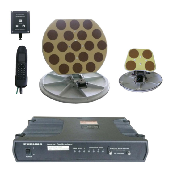
Page 85: Chapter 1 Overview
Chapter 1. Overview 1.1 System Configuration 1.1 System Configuration Note) The equipments connected with a dotted line with the Communication unit are optional equipments. Fig. 1.1.1 System configuration Table 1.1.1 Standard supply for FELCOM-250/500 Quan- Name Model Code number Notes tity FB-1500-A 000-015-776... - Page 86 1.1 System Configuration Table 1.1.2 Architecture of options for FELCOM-250/500 Name Model Code number Notes Engineering work material Incoming indicator FB-3000 CP16-04001 attached Telephone Engineering work material FC755D1 equipment CP16-00511 and 00512 attached Engineering work material FAX-2810 CP16-03510 attached Transformer TSU-N05E +cable Transformer OP16-25 004-446-850...
-
Page 87: Overview Of The Fleet Broad Band
1.2 Overview of the Fleet Broad Band (FB) 1.2 Overview of the Fleet Broad Band (FB) 1.2.1 Satellite Coverage There are 3 satellites used for BGAN, and they are the 4 generation satellites, I-4. The arrangements of the satellites are different from those used for Fleet-77. Fig. -
Page 88: Ground Facilities
1.2 Overview of the Fleet Broad Band (FB) Satellite beam The satellite beam is consisted of 3 different types of beams. 1 Global Beam for each ocean area (elevation angle: 10 degree or more) 19 Regional beams, each covering the area of the diameter of 3000 km Approx. - Page 89 1.2 Overview of the Fleet Broad Band (FB) 1) Satellite Access Stations (SAS) The 3 SASs provide communication links/interfaces between each of the Inmarsat-4 satellites and the communication networks on earth. Each SAS is owned and operated by INMARSAT, is equipped of an antenna for communicating with the satellites, and is directly connected with PSTN, ISDN, and the Internet.
-
Page 90: Registration
1.2 Overview of the Fleet Broad Band (FB) 1.2.3 Registration The FB terminal used for the communication will need to be registered in the RNC (Radio Network Controller). As a result of this registration, connection between UE(User Equipment) and RNC will be established, and then the “procedure to Attach”... -
Page 91: Service
Fig. 1.2.5 The three data networks 1.2.5 Service 1. Service Types Furuno supply FELCOM-250 and 500 (2009/11), there are two classes set for the Fleet Broad Band, and each of them has different services provided. Table 1.2.1 Services provided FELCOM-250: Low Gain Type (Class 9) -
Page 92: Example Communication Rates
1.2 Overview of the Fleet Broad Band (FB) 8 kbps 16 kbps 64 kbps 32 kbp 256 kbps 432 kbp 128 kbps Standard IP data The 432 kbps(class 8) satellite channel Streaming IP data will be shared, and billing will be made The user will select the guaranteed bit according to the data amount. -
Page 93: Example Selection Of The Services
1.2 Overview of the Fleet Broad Band (FB) 3. Example Selection of the Services Table 1.2.3 Example Selection of the Services Application type IP Connection E-Mail Standard IP data Internet Browsing Standard IP data Standard IP data Standard IP data Voice AMBE 2 (4 kbps) / Standard IP data VoIP... -
Page 94: Circuit-Switched Data Service (Circuit Switching Service)
1.2 Overview of the Fleet Broad Band (FB) The FB terminals are enabled to establish connection for the Streaming IP deata service provided and for 2 or more connections for Streaming IP data. The actual data rate and maximum number of Streaming IP data connections varies and depends upon the type of terminal used, link conditions, available capacity an elevation to the satellite. - Page 95 1.2 Overview of the Fleet Broad Band (FB) Table 1.2.4 Examples of abbreviated codes Abbreviated Action code Access to a DP's directory enquiry system Access to a DP's ISP service Access to a DP's customer service / technical help desk Access to a DP's credit card calling system Access to a DP's automatic loop back / test system Emergency call (connect to RCC)
-
Page 96: Service Contract
1.2 Overview of the Fleet Broad Band (FB) 1.2.7 Service Contract Example) Subscribing for JSATMOBILE 1) Price Plans As in the contracts for mobile phones, there are different price plans according to the type of services provided, communication volume, and usage hours. 2) Additional Service “4 k AMBE”... - Page 97 1.2 Overview of the Fleet Broad Band (FB) 1-13...
-
Page 98: Network Connection
1.2 Overview of the Fleet Broad Band (FB) 1.2.8 Network Connection Fig. 1.2.7 The setup for the communication sent from Mobile and received by CS (Circuit Switched Call) Fig. 1.2.8 The Clearing on the Mobile side for a CS (Circuit Switched Call) communication 1-14... - Page 99 1.2 Overview of the Fleet Broad Band (FB) Fig. 1.2.9 The setup for the communication sent from CS (Circuit Switched Call) and received by Mobile Fig. 1.2.10 The Clearing on the CS side for a CS (Circuit Switched Call) communication 1-15...
-
Page 100: Have The Web Mmi For Felcom-250/500 Displayed
1.3 Have the Web MMI for FELCOM-250/500 Displayed 1.3 Have the Web MMI for FELCOM-250/500 Displayed 1.3.1 Overview You can execute setups, maintenance, and connection/disconnection of Standard IP data or Streaming IP data upon the Web MMI for FELCOM-250/500. In order to establish communication, you will need to establish LAN connection the PC and the Communication unit, and to have a SIM card inserted into the SIM card slot of the Communication unit. -
Page 101: Have The Web Mmi Displayed
1.3 Have the Web MMI for FELCOM-250/500 Displayed 1.3.2 Have the Web MMI Displayed Step 1) Network settings for the PC Note) The following description is made that Own IP address is the default value “192.168.1.1, 255.255.255.0/(24)”. When the OS of the PC is Vista, it is recommended that Ipv6 is set to OFF. - Page 102 1.3 Have the Web MMI for FELCOM-250/500 Displayed Step 2) Make the settings for Internet Explorer (IE) When the OS is Windows XP; Activate IE, and click; [Tools] -> [Internet options] -> [Connection] -> [LAN setup], and remove the tick from “Use the proxy server for the LAN”. When the OS is Windows VISTA;...
- Page 103 1.3 Have the Web MMI for FELCOM-250/500 Displayed Step 3) Have the Web MMI displayed Activate Internet Explorer, and enter “http://192.168.1.1” into the URL field. Or, Open the CD-ROM (supplied with accessories) and copy “FELCOM500” shortcut icon to the desktop of the PC. Double-click the “FELCOM500” shortcut icon on the PC desktop.
- Page 104 1.3 Have the Web MMI for FELCOM-250/500 Displayed Step 4) Handling the Web MMI The Web MMI is equipped with the User mode, the Administrator's mode where settings can be made, and the Service mode where settings can be made and maintenance works can be executed.
-
Page 105: Chapter 2. Handling Password
Chapter 2. Handling Password 2.1 SIM Password (PIN Code) 2.1 SIM Password (PIN Code) 2.1.1 Enter the PIN Code Fig. 2.1.1 Handling of PIN code and PUK code Procedure) 1. Insert the SIM card for INMARSAT FB provided by the provider into the SIM card slot, and turn the power on. - Page 106 2.1 SIM Password (PIN Code) 2. Activate Internet Explorer, enter “http://192.168.1.1” into the URL field and press [Enter] to have the Web MMI for the FELCOM-250/500 activated. 3. When the PIN Enable/disable in the SIM menu is set to “PIN Enable”, “Now Loading”...
- Page 107 2.1 SIM Password (PIN Code) About SIM Cards SIM cards have 4 passwords; PIN1 code, PUK1 code, PIN2 code, and PUK2 code. The FELCOM-250/500 does not use PIN2 code and PUK2 code. When you are requested for the PIN code or the PUK code, enter PIN1 or PUK1. ICC-ID PIN, PUK code Make sure not to lose the SIM card holder.
-
Page 108: Handling The Sim Card
2.1 SIM Password (PIN Code) 2.1.2 Handling the SIM Card 1. PIN Code and PUK Code If you fail to enter the PIN code for 3 consecutive times, the SIM card will be forced to be locked. This locked status can be released by entering the “PUK code”. If you fail to enter the PUK code for 10 consecutive times, the SIM card will become unavailable. -
Page 109: Change The Pin Code
2.1 SIM Password (PIN Code) 2. Change the PIN Code You can execute the following operations via the “SIM” menu upon the Web MMI. Make a setting not to be required for the PIN code to be input when the power is turned on. -
Page 110: Ota Settings
2.1 SIM Password (PIN Code) 3. OTA Settings OTA is the abbreviation for “Over The Air”, and it refers to the function for rewriting the SIM contents via satellite link. Make the settings by selecting; Settings -> Basic settings -> OTA. Make sure to select “Enable”... -
Page 111: Administrator's Mode And Service Mode
2.2 Administrator's Mode and Service Mode 2.2 Administrator's Mode and Service Mode The Web MMI for FELCOM-250/500 has an Administrator's mode screen where settings can be made, and a Service mode screen where settings and maintenance works can be executed. To call these screens, the Username and Password for each mode will be required. - Page 112 2.2 Administrator's Mode and Service Mode Reference) 1) Changing the password for the Administrator's mode You can change the password by; Settings -> Change password. The number of valid characters is 4 to 8 characters. If you have forgotten the password you had set up, you can follow the procedure described below;...
-
Page 113: Call The Service Mode
2.2 Administrator's Mode and Service Mode 2.2.2 Call the Service Mode Click [admin login] to have the “Administrator login” screen displayed, and then enter the following; If you do not execute any operation for 15 minutes, the screen will return to the Users' screen. -
Page 114: Sms Password
2.3 SMS Password 2.3 SMS Password To enter the SMS menu for the Web MMI or the Handset, you will need to enter the SMS password. The passwords are the same for the Web MMI and the Handset. The default value of this password is the same with the password for the Administrator's mode;... -
Page 115: Enter The Sms Menu For The Handset
2.3 SMS Password 2. Enter the SMS menu for the Handset When you wish to enter the SMS menu from each Handset, enter the password you had set via Settings -> SMS server setting to log into the SMS menu. As in the case for the Web MMI, if you place a tick for “Save password”... -
Page 116: Handling The Password
2.4 Handling the Password 2.4 Handling the Password 2.4.1 List of Passwords Table 2.4.1 List of passwords User Name Applied for; /Password Notes (Default) User name: The password alone can be changed : Settings -> Change password Calling Administrator's Admin The menus of "Settings", "Log", "Device", and "Self test"... -
Page 117: The Procedure For When You Have Forgotten The Password
2) Connect the Handset to the LAN port while pressing the [ON Hook] key and the [*] key at the same time. Keep on pressing those keys. 3) Keep on pressing the keys until the screen on the Handset changes from white to “black”, or until the logo “FURUNO” is displayed. 2-13... -
Page 118: The Procedure For When You Have Forgotten The Pin Code
2.4 Handling the Password 3. The procedure for when you have forgotten the password you had set for SMS Execute initialize the Communication control unit. Open; “Settings” -> Initialize, and execute Initialize except connection setting. 4. The procedure for when you have forgotten the PIN code you had set for Intentionally fail to enter the PIN code for 3 times, enter the PUK code, and then set a new PIN code. -
Page 119: Chapter 3. Menu Tree
Chapter 3. Menu Tree 3.1 Web MMI 3.1 Web MMI 3.1.1 The Structure of the Web MMI Position and Model name Administrator Signal intensity Date / time display Alarm display display Log-in/out display Navigation bar area Menu display area Contents display area User authentication area The Web MMI has 3 different modes;... -
Page 120: Users' Mode
3.1 Web MMI 1. Users' Mode Main Contacts 2. Administrator's Mode (Username: Admin, Password: 01234567) Additionally to Main, SMS, Contacts, and SIM displayed for the Users' mode, Setting, Device, Log, and Selftest will be added. 3. Service Mode (Username: Service, Password: fb5963) Additionally to Main, SMS, Contacts, and SIM displayed for the Users' mode, Additionally to Setting, Device, Log, and Selftest for the... -
Page 136: Handset
3.2 Handset 3.2 Handset 3.2.1 The Structure of the Handset Screen Time displayed The Signal strength Information from the NTP server displayed Position data displayed The currently acquired satellite Elevation angle displayed The currently connected PS (circuit switching service) displayed: Voice, Fax, UDI, RDI Date / time displayed Streaming or Standard... -
Page 147: Chapter 4. Settings For Tel/Fax
Chapter 4. Settings for TEL/FAX 4.1 Overview 4.1 Overview Handset: The settings for the phone function will need to be made for both the Communication unit and the Handset. Analog terminal(TEL/FAX): The settings for the phone function will need to be made the Communication unit. -
Page 148: Settings On The Handset
4.1 Overview 2. Settings on the Handset The items requiring setting are displayed via Settings -> SIP menu. Make sure to make the settings for “Client set.” The settings for Proxy server, S/L port, Expire time, and RTP port in SIP menu do not need to be changed. Registration of contacts can be made in Contacts settings menu and Phone book. -
Page 149: Handling The Service Types
4.1 Overview 4.1.2 Handling the Service Types There are two service types: 4k AMBE and 3.1k Audio. In normal cases, voice calls will be made via 4k AMBE, and FAX calls will be made via 3.1k Audio. When you intend to make a call from FB terminal by changing the service type from 4k AMBE to 3.1k Audio, attach the service code “2*”... -
Page 150: Overview Of The Settings
4.1 Overview 4.1.3 Overview of the Settings In order to use the Handsets, the extension number and the password for each Handset will need to be registered in the SIP server build in the HUB board in the Communication unit. The same extension number and password will need to be registered in the Handset, which will be the client device. - Page 151 4.1 Overview Connection settings for the Analog TEL/FAX Mandatory item: Basic settings -> Analog ports -> TEL, FAX Handset registration settings Register the Handset extension number and the password into the SIP server from the Web MMI Mandatory item: Settings -> PBX Settings -> Extension Register the Handset extension number and the password from the Handset Mandatory item;...
- Page 152 4.1 Overview Note) When you intend to connect the Handsets or the Incoming indicator via the SW HUB, the SW HUB will need to be one of the PoE specifications. Turn Dip SW #1 to ON, and set to “PB” System setting Register the extension number and password for each Handset.
-
Page 153: Settings For Analog Port: Tel/Fax
4.2 Settings for Analog port: TEL/FAX 4.2 Settings for Analog port: TEL/FAX (Mandatory) Basic settings -> Analog ports The Analog port numbers for TEL1-4 of the Communication unit correspond to the numbers shown on the “Analog ports” setting screen. For example, if you intend to connect an Analog phone to TEL 1, the setting for “Analog port1”... - Page 154 4.2 Settings for Analog port: TEL/FAX 2. Select the terminal connected to “TEL 1-4” from among the pull down menu for “Type.” Telephone : Service type: calls will be made via 4k AMBE : Service type: calls will be made via 3.1k Audio Telephone and FAX : Service type: Telephone and FAX acknowledged automatically Reference)
- Page 155 4.2 Settings for Analog port: TEL/FAX : Register in the SIP server Edit by clicking Edit Extension screen Incoming routing screen Call limit screen Group screen...
-
Page 156: Registering The Handsets In The Sip Server
4.3 Registering the Handset in the SIP Server 4.3 Registering the Handsets in the SIP Server (Mandatory) You will need to allocate IP addresses to the Handsets. The Communication unit is mounted with the DHCP server function, and IP addresses are allocated automatically in normal. - Page 157 4.3 Registering the Handset in the SIP Server 2. Select from the Handset; Settings -> 2. Network -> Password -> 1. Automatic. The message “Information Set” will be displayed. The default value is “Automatic,” Make this confirmation on each Handset. Note) The default password for the administrator is “01234567.”...
-
Page 158: Web Mmi: Registering In The Sip Server
4.3 Registering the Handset in the SIP Server 4.3.2 Web MMI: Registering in the SIP Server (Mandatory) Step-2) Settings -> PBX Settings -> Extension You will need to register the extension numbers and the passwords for the Handsets in the SIP server from the Web MMI. You can register 30 sets. The same extention numbers and passwords will need to be registered in the Handsets, too. - Page 159 4.3 Registering the Handset in the SIP Server 2. From the Settings menu, open; PBX Settings -> Extension. 3. Click Add extension to open the setting screen, and enter the extension “Number”, “Password”, and “Note”. Number: The extension number. Register a 4-digit number from 1000 to 9999. It is recommended that you allocate the numbers in a definable format.
-
Page 160: Edit The Registered Data
4.3 Registering the Handset in the SIP Server 1. Edit the Registered Data In order to edit the registered data, click Edit. If you have changed the “Number” or “Password”, you will need to change the settings for the corresponding Handset accordingly via; Settings -> “SIP.” 2. -
Page 161: Handset: Register Terminal Number And Password
4.3 Registering the Handset in the SIP Server 4.3.3 Handset: Register Terminal Number and Password (Mandatory) Step-3) Settings -> SIP -> Client set According to the list created in Step-2, make the settings for the Handset extension number; extension Number, Password, and Nickname. The setting can be made via; Settings ->... - Page 162 4.3 Registering the Handset in the SIP Server Nickname Caller's extension number When receiving an extension call When registration in the SIP and registration of the client Handset have been completed, “ ” will be displayed in Reg. column. It may take approx. 1 min (Max.) until the mark is displayed after the registration was completed.
- Page 163 4.3 Registering the Handset in the SIP Server 3) Place a tick for the Handset or Incoming indicator you wish to register or edit. 4) If you click Add to detect list, the device will move to “Device list”. Open “Device list.”...
-
Page 164: Confirm The Other Settings In The Sip Menu
4.3 Registering the Handset in the SIP Server 4.3.4 Confirm the Other Settings in the SIP menu (Mandatory) Step-4) Settings -> SIP -> Client set In the SIP menu, there are settings such as Proxy server, S/L port, Expire time, and RTP port additionally to Client set. -
Page 165: Expire Time
4.3 Registering the Handset in the SIP Server 3. Expire time The Expire time is the setting for the Handset authentication expiry time. The default value is 3600 sec. The value can be set between 1800 to 7200 seconds. When the time set here has passed, the SIP server cancels the authentication once, and authenticates the Handset once again. -
Page 166: Setting The Incoming Routing
4.4 Setting for the Incoming Routing 4.4 Setting the Incoming Routing (Mandatory) 4.4.1 Setting the Incoming Routing Set the incoming call route (call incoming order) via; PBX settings -> Incoming routing. It is a setting for distinguishing which terminal is to receive the phone call (4k AMBE and 3.1k) and FAX (3.1k Audio). - Page 167 4.4 Setting for the Incoming Routing 3. Place a tick for the “Number” which will be the call targets. Also make the setting for “2 rings after 30 second ---,” which is the setting for the number of seconds when the call will be transferred in the case there is no response. Make sure to place a tick for the “1 ring”...
-
Page 168: Setup Example
4.4 Setting for the Incoming Routing 4.4.2 Setup Example Setup example-1) When a call is received by the phone of the phone number 870 77xxxxxxx (4k AMBE), the status of No.1 Analog phone and No. 1 Handset is changed to “Ringing,” and if there is no response from both, the call is forwarded to No. - Page 169 4.4 Setting for the Incoming Routing Setup example-3) When receiving the call by FAX number: 870 77yyyyyyy (3.1k Audio: 64 kbps), and having the FAX be Ringing, and when a 3.1k Audio call for No. 1 Analog phone is received by phone number: 870 77xxxxxxx (AMBE: 4 kbps), the statuses for No. 1 Analog phone, No.
- Page 170 4.4 Setting for the Incoming Routing Reference) What does (1) in “Missed call (1)” mean? When the call is forwarded to the terminal which is set as 2 ring, the screen for the Handset where the tick is placed for 1 ring will have “Missed call (1)”...
-
Page 171: Setting For The Call Limit
4.5 Setting for the Call limit 4.5 Setting for the Call limit Limitation settings for making phone calls can be made via; PBX settings -> Call limit. This setting is made for limiting the phone calls made from the Handsets or the Analog phones. -
Page 172: Group Registration For Extension Calls: Group
4.6 Group Registration for Extension Calls: Group 4.6 Group Registration for Extension Calls: Group Group registrations for extension call can be made via; PBX settings -> Group. When a call is made for the “Number” of a group registered, all terminals registered in the group will be called, and first, the extension call will be made between the off hook terminals. - Page 173 4.6 Group Registration for Extension Calls: Group 5. Enter the numbers for the group members in the range of “1000 to 9999” into the Member field, and enter a group name consisting of 50 characters at maximum. 6. If you click Add, the group registration screen will be displayed. 1) Edit the Registered Data To edit the registered data, click Edit within the box.
-
Page 174: Setting For The Incoming Indicator
4.7 Setting for the Incoming Indicator 4.7 Setting for the Incoming Indicator Basic settings -> Incoming indicator This is the setting for the ringing pattern and for whether the Incoming indicator is to have the ringing made or not for when phone, FAX, UDI, and RDI received incoming calls. -
Page 175: Registering The Contacts
4.8 Registering the Contacts 4.8 Registering the Contacts You can register the phone number from the Web MMI or from each Handset. The registered data can be saved in the Communication unit, the SIM card, and the data can be used commonly between the Handsets or the Web MMI. You can also specify the storage location as each individual “Handset”... - Page 176 4.8 Registering the Contacts 1. Edit the Registered Data In order to edit the registered data, click Edit. When the “Contacts list” screen is displayed, re-edit the date on this screen. 2. Delete the Registered Data To delete the registered data, place a tick for the “Name” you wish to delete, and click Delete.
-
Page 177: Registering The Contact From The Handset Screen
4.8 Registering the Contacts 4.8.2 Registering the Contact from the Handset Screen 1. Register the contact from the Handset screen 1. Press the key on the idle screen, open the address book, and select the “Handset”. The data for the contact will be registered in the Handset, and this data will be able to be used by the registered Handset only. - Page 178 4.8 Registering the Contacts 3. The screen will switch to Registration screen; select [New] and press “Apply.” Then the phone number will be automatically entered in the [No.] field for the contact registration screen. Register the name of the contact in the [Name] field, and press “Apply”...
-
Page 179: Setting For The Analog Phone: Fc755D1
4.9 Setting for the Analog Phone: FC755D1 4.9 Setting for the Analog Phone: FC755D1 Change the dialing method for the Analog phone from DP method (dial pulse method) to PB method (push button method). Procedure) 1. Remove the record sheet holder and the name tag form. 2. -
Page 180: Setting For Fax: Fax-2810/2820
4.10 Setting for FAX: FAX-2810/2820 4.10 Setting for FAX: FAX-2810/2820 FAX-2810 : Japanese character machine, 100VAC type FAX-2820 : CE supported English character machine, 220VAC type The operations are the same for FAX-2810 and FAX-2820. Settings are required for the ECM and the Modem. FAX-2810 FAX-2820 4.10.1 ECM ON/OFF Setting... -
Page 181: Modem Settings
4.10 Setting for FAX: FAX-2810/2820 Setting and Selector No. Function Specifications ECM in sending 0: ON 1: OFF ECM in receiving 0: ON 1: OFF Call Waiting Caller ID 0: ON 1: OFF Not used 0: 0% 1: 8% Acceptable TCF bit error rate (%) 0: 0% 1: 4% (Only at 4800 bps) 0: 0% 1: 2%... -
Page 182: Initializing Eeprom
4.10 Setting for FAX: FAX-2810/2820 Selector No. Function Setting and Specifications 00: 0 km 10: 3.6 km Cable equalizer 01 : 1.8 km 11: 5.6 km 00: -43 dBm 10: -49 dBm Reception level 01: -47 dBm 11: -51 dBm 0 : 0 dB 1 : 8 dB Modem attenuator... -
Page 183: Print Out The Wsw Setup Value
4.10 Setting for FAX: FAX-2810/2820 4.10.4 Print Out the WSW Setup Value Procedure) 1. Quickly press the keys in the order of [Menu/set][*][2][8][6][4] to enter the maintenance mode. 2. Once the equipment has entered in the maintenance mode, “MAINTENANCE” will be displayed on the LCD. -
Page 184: Chapter 5. Wan Settings
Chapter 5. WAN Settings 5.1 WAN Settings 5.1 WAN Settings 5.1.1 Overview You will make the settings for Standard IP data and Streaming IP data in this chapter. The settings will be made via; Setting -> Network settings -> WAN, and they are for the service types, application types, connection passwords, information from the provider (connection IP, DNS Server IP, etc.), and Network connection/disconnection conditions. -
Page 185: Wan Settings
5.1 WAN Settings 5.1.2 WAN Settings 1. Add connection: Add Streaming IP data The WAN/Add connection settings will be reflected onto; Main -> Data connections. The settings will also be reflected onto the Web MMI of other PCs which are connected to the network. - Page 186 5.1 WAN Settings Setup item Setup value Notes Shared & Best effort FELCOM-500: 432 kbps Standard data FELCOM-250: Up link/239 kbps, Down link: /284 kbps 8 kbps Streaming Data communication will be executed via the specified Service 16 kbps Streaming service.
-
Page 187: Edit: Editing The Services
5.1 WAN Settings 2. Edit: Editing the Services If you click Edit for the Service you intend to execute editing for, the editing screen for that service will be displayed, and you will be able to edit the service using that screen. If you have forgotten the Operation password you had registered, open Edit, and newly register a password once again. - Page 188 5.1 WAN Settings Setup item Notes Enter the User account and Password specified by the provider. If you User account enter incorrect data, you will not be able to connect with the provider. If no user account or password is specified by the provider, leave these Password fields blank.
-
Page 189: Connecting With Wan
5.1 WAN Settings 5.1.3 Connecting with WAN 1. Connecting with WAN from a PC When you intend to communicate via Standard IP data or Streaming IP data, open “Data connection” from the Main menu, select the service you intend to communicate with, and click Connect. - Page 190 5.1 WAN Settings What does the "P" mark mean? “P” stands for the “Primary” route, and for instance is displayed for the Standard IP data service which had been connected first, and the port number will not be specified regardless of the settings for the Applications such as FTP or Windows Media Player. If the service connected next is Streaming IP data for 256 kbps, and the application is Windows Media Player, the port number allocated for that connection will be used for establishing connection as the Secondary route.
- Page 191 5.1 WAN Settings Reference) If connection with the Internet (WAN) is established via either Standard IP data or Streaming IP data, “D: Connected” will be displayed upon the Handset screen. The Data Connection field for the Status monitor screen will change to “Connected”, too. Data connection If connection is established either via Standard IP data or via any of Streaming IP data, the display will change to “Connected”.
-
Page 192: Connecting To Wan From The Handset
5.1 WAN Settings 2. Connecting to WAN from the Handset If you connect with the Internet (WAN) from the PC via Standard IP data or Streaming IP data, you will be able to implement data communication from the Handset via the service you had connected first. Connection can be initiated from the Handset via the Standard IP data service only, and cannot be initiated from Streaming IP data. - Page 193 5.1 WAN Settings Web settings for the Handset Make Web settings for each Handset by following; Web top page -> 4. Settings. Web top Menu-1 Menu-2 Overview Large 1. Font size Medium The setting for the Web page character size Small 200% 150%...
-
Page 194: Diagnostics
5.2 Diagnostics 5.2 Diagnostics You can confirm the Internet connection status. From the Web MMI, select; Settings -> Network settings, and open “Diagnostics”. In the Ping field; Enter the IP address or the domain name of the counterparty. If the counterparty makes a response, you will receive the response. In normal cases, the network route between hosts will be determined as operating normally if the ping command is executed in a normal manner and packet lost does not occur. -
Page 195: Response Example
5.2 Diagnostics Response example: 1) Enter "Google.co.jp" into the Ping field PING google.co.jp (74.125.91.104) 56(84) bytes of data. 64 bytes from qy-in-f104.google.com (74.125.91.104): icmp_seq=1 ttl=50 time=30.0 ms 64 bytes from qy-in-f104.google.com (74.125.91.104): icmp_seq=2 ttl=50 time=2360 ms 64 bytes from qy-in-f104.google.com (74.125.91.104): icmp_seq=4 ttl=50 time=1160 ms 64 bytes from qy-in-f104.google.com (74.125.91.104): icmp_seq=3 ttl=50 time=2160 ms 64 bytes from qy-in-f104.google.com (74.125.91.104): icmp_seq=5 ttl=50 time=40260 ms --- google.co.jp ping statistics ---... -
Page 196: Enter "Google.co.jp" Into The Nslookup Field
5.2 Diagnostics 3) Enter "Google.co.jp" into the Nslookup field Query about google.co.jp for record types ANY Trying google.co.jp ... Query done, 4 answers, status: no error The following answer is not authoritative: google.co.jp 111236 IN ns1.google.com google.co.jp 111236 IN ns4.google.com google.co.jp 111236 IN ns3.google.com... -
Page 197: Entering Google.co.jp Into Ping
5.2 Diagnostics Reference) Examples for when executing Ping and Nslookup from the PC command prompt 1) Entering google.co.jp into Ping Microsoft Windows XP [Version 5.1.2600] (C) Copyright 1985-2001 Microsoft Corp. C:¥Documents and Settings¥installuser>ping google.co.jp Pinging google.co.jp [74.125.91.104] with 32 bytes of data: Request timed out. -
Page 198: Entering Google.co.jp Into Nslookup
5.2 Diagnostics 2) Entering google.co.jp into Nslookup Microsoft Windows XP [Version 5.1.2600] (C) Copyright 1985-2001 Microsoft Corp. C:¥Documents and Settings¥installuser>nslookup google.co.jp Server: felcom-comhub Address: 192.168.1.1 Non-authoritative answer: Name: google.co.jp Addresses: 74.125.91.104, 72.14.203.104, 74.125.95.104 C:¥Documents and Settings¥installuser>nslookup Default Server: felcom-comhub Address: 192.168.1.1 >... - Page 199 5.2 Diagnostics > > set type=mx > google.co.jp Server: felcom-comhub Address: 192.168.1.1 DNS request timed out. timeout was 2 seconds. Non-authoritative answer: google.co.jp MX preference = 10, mail exchanger = smtp4.google.com MX record: google.co.jp MX preference = 10, mail exchanger = smtp3.google.com set type=mx google.co.jp MX preference = 10, mail exchanger = smtp2.google.com...
-
Page 200: Chapter 6. Udi/Rdi Communication
Chapter 6. UDI/RDI Communication 6.2 Settings FELCOM-500 can operate ISDN UDI/RDI communication, but FELCOM-250 cannot operate this service. There is a case where this service is not available depending on to the subscription contract with the provider (SIM card). 6.1 Overview 64 k UDI (Unrestricted Digital Information) and 56 k RDI (Restricted Digital Information) for the ISDN communication will be executed using the serial port for the Communication unit. -
Page 201: Settings
6.2 Settings 6.2 Settings 6.2.1 Install the Standard Modem into the PC Procedure 1. Open; [Start] -> Settings -> Control panel -> “Phone and modem options”. 2. Open the [Modem] tab, and click Add. The “Add Hardware Wizard” will be displayed. - Page 202 6.2 Settings 4. In the next screen, select the “Port” you wish to install the modem to, click Next, and click Finish to complete installing the modem. 5. In “Phone and modem options”, open the [Modem] tab, select the Standard 33600 bps Modem you had installed, and open Properties.
-
Page 203: Settings For The Dial-Up Connection
6.2 Settings 6.2.2 Settings for the Dial-Up Connection Procedure 1. Select; [Start] -> Settings -> Control panel -> “Network connection”, and open “Create connection wizard”. 2. The screen “New connection wizard” will be displayed. Click Next. 3. In the screen “Network connection type”, place a tick for “Connect to the Internet”, and click Next. - Page 204 6.2 Settings 5. In the next screen, place a tick for “Connect using a dial-up modem”, and click Next. 6. The screen “Select a device” will be displayed. Select “Modem – Standard 33600 bps modem” only, and click Next. 7. In the screen “Connection Name”, enter the “ISP Name” for the target connection, and click Next.
- Page 205 6.2 Settings 8. In the screen “Phone Number to Dial”, enter the connection target phone number, and click Next. The phone number should consist of; “00 + country code + area code + subscriber's number”. Example: 0081786312274 9. In the screen “Internet Account Information”, enter the “User name” and “Password”...
-
Page 206: Settings For Incoming Connections
6.2 Settings 6.2.3 Settings for Incoming Connections The network administrator should make these settings according to the network environment. Procedure 1. Select; [Start] -> Settings -> Control panel -> “Network connection”, and open “Create connection wizard”. 2. The screen “New Connection Wizard” will be displayed. Click Next. 3. - Page 207 6.2 Settings 5. In the screen “Devices for Incoming Cnnections”, select “Modem – Standard 33600 bps modem” only, and click Next. 6. The screen “Incoming Virtual Private Network (VPN) connection” will be displayed. If the counterparty network is connected directly using an ISDN line, place a tick for “Do not allow virtual private connections”, if the counterparty network is connected via the Internet, place a tick for “Allow virtual private connections”, and click Next...
- Page 208 6.2 Settings 7. Click Add on the screen “User Permission”. The screen “New user” will be displayed. 8. In the screen “New user”, set the data for the user you allow the connection for. If you click OK, the user will be added to the list “User Permission”. Confirm that a tick is placed for the user name you had added, and click Next.
- Page 209 6.2 Settings 10. In “TCP/IP address assignment”, place a tick for “Assign TCP/IP address automatically using DHCP”, and click OK. This setting is made to enable Windows to automatically allocate a private IP address for the IP address of the calling side. Click Next. 11.
-
Page 210: Settings For The Communication Unit
6.2 Settings 6.2.4 Settings for the Communication unit From Settings in the Web MMI, enter Basic settings menu, and make the settings for “RS-232C: Serial port”. The settings made here are those for the communication between the PC and the Communication unit. -
Page 211: Connecting To The Network Using Udi
6.3 Connecting to the Network Using UDI 6.3 Connecting to the Network Using UDI Open the dial-up connection you have created, and click Dial. The “Call” will start; enter data for “Confirm the user name and password”, and “Register for the network”, and you will be connected to the network. The following example is the dial-up connection for when accessing to “KDDI 28#”. -
Page 212: Chapter 7. Lan Settings
Chapter 7. LAN Settings 7.1 LAN IP address In normal cases, it is recommended to set the setting for "DHCP server" to "Use" so that the IP address is automatically allocated from DHCP. Note) The own IP address (for the HUB) and the IP addresses for DHCP, DNS, and SIP are the same. - Page 213 7.1 LAN IP address Reference) For example, if the Subnet mask is 255.255.255.0/24, and is represented in binary numbers as 11111111 11111111 11111111 00000000, the first 24 bits within the IP address will be the network address, the last 8 bits will be the host address, and “/24” will be the network address.
-
Page 214: Dhcp Server
7.1 LAN IP address 7.1.2 DHCP server FELCOM-250/500 are equipped with the DHCP (Dynamic Host Configuration Protocol) function, the DHCP will automatically allocate the IP addresses to the terminals connected to the network in normal cases. In this case, make the setting for DHCP server to “Use”. -
Page 215: Lease Information
7.1 LAN IP address 2. Lease information To confirm the IP address allocated by DHCP server, open Lease information. Note) When the setting for DHCP Use/Unuse is set to “Unuse”, this information will not be valid. Each device (client) will need to make the network settings only, and there is no need to add them to this list. -
Page 216: Confirm The Ip Address
7.1 LAN IP address 1.3) Add lease When you wish to add a terminal to the network that would require a new Static IP address to be allocated, click Add lease. Enter the MAC address and the IP address for the terminal which is to be added. 1.4) Delete Select the device you wish to delete from the network, and click Delete. - Page 217 7.1 LAN IP address When you have entered ipconfig Microsoft Windows XP [Version 5.1.2600] (C) Copyright 1985-2001 Microsoft Corp. C:¥ >ipconfig Windows IP Configuration Ethernet adapter local area connection: Connection-specific DNS Suffix . : IP Address... . : 192.168.1.192 Subnet Mask .
-
Page 218: Using Static Ip Addresses
7.1 LAN IP address 4. Using Static IP addresses There are two methods for setting fixed IP addresses for the PCs and Handsets; you can either set Auto or Manual for the client IP address setting. FB-2000 Manual Network login by fixed IP Handset Allocating a fixed IP by “Manual”... - Page 219 7.1 LAN IP address 2) Setting a static IP address by the Manual setting for the PC This method sets a Static IP address on the PC side and does not use the DHCP server for the communication unit. 2.1) As for the PC setting, select Local area connection, open Internet protocol (TCP/IP) ->...
- Page 220 7.1 LAN IP address 4) Setting a fixed IP address for the handset This method sets a Static IP address on the Handset side and does not use the DHCP server for the communication unit. 4.1) Upon the Handset, select; Settings -> Network -> Administrator’s password: 01234567 ->...
-
Page 221: Routing
7.1 LAN IP address 7.1.3 Routing This setting should be implemented by the administrator. The outline of the procedure will be described here. This is the setting for when the Router is connected to the communication unit, and when a different network is newly established. Settings can be made for up to 20 network cases. -
Page 222: Destination
7.1 LAN IP address 1. Destination Enter the network address for the Router connected to the communication unit. The IP address is “172.16.0.0”, and therefore the Subnetmask setting will be 255.255.0.0/16. 2. Gateway Set the IP address for the Router side port connected with FB-2000 for the Gateway. The actual IP address here will be 192.168.1.2, and make the IP address a static IP address. -
Page 223: Rip
7.1 LAN IP address 7.1.4 RIP This setting should be implemented by the administrator. The outline of the procedure will be described here. RIP stands for Routing Information Protocol. This function is equipped in the communication unit. If you connect a Router equipped with the RIP function to the communication unit, they will be able to dynamically exchange route information. -
Page 224: Vrrp
7.1 LAN IP address 7.1.5 VRRP This setting should be implemented by the administrator. The outline of the procedure will be described here. *** Note that this function is currently not fully supported. *** VRRP stands for Virtual Router Redundancy Protocol, and this function is equipped in the communication unit: FB-2000. -
Page 225: Enable/Disable
7.1 LAN IP address 1. Enable/Disable This setting is made to set Enable/Disable for the VRRP function. Set Enable for both No.1 and 2 FB-2000. 2. Name Set the same name for No.1 and 2. You can set a name consisted of 50 characters at maximum, and spaces cannot be used. -
Page 226: Preempt Mode
7.1 LAN IP address 7. Preempt mode If you set “Enable” for this setting, the equipment activated first will have higher priority. If you set Disable, the priority will be determined according to the Priority setting. 8. Status If you set Preempt, the display will change from “VRRP is not enable” to “MASTER”... -
Page 227: Chapter 8. Security Settings
Chapter 8. Security Settings 8.1 Security Settings 8.1 Security Settings 8.1.1 Firewall This setting should be implemented by the administrator. The outline of the procedure will be described here. There is a Firewall function which prevents from having external intrusions to the FELCOM-250/500 network. -
Page 228: Prohibit Windows-Update
8.1 Security Settings 4. Prohibit Windows-Update The “HUB” embedded in the Communication unit will prohibit from having Windows update automatically executed by the PC. Reference) To prohibit the update procedure in the PC, open the Control panel, and in “Automatic updates”, set “Prohibit automatic updates”. 8.1.2 IP Filter This setting should be implemented by the administrator. -
Page 229: Upnp (Universal Plug & Play)
8.1 Security Settings 2. Upnp (Universal Plug & Play) If you place a tick for this setting, when the application supporting UpnP is activated, the setting according to that application will be executed for the “HUB” installed in the Communication unit. 8.1.2.2 IP filter list IP filter doesn't work when IP filter list is not set. - Page 230 8.1 Security Settings 3) DST. Address, From address Note that Network IP address cannot be specified. When the direction is set to WAN -> LAN, specify the IP address for the LAN PC/server for the “DST. address”, and specify the sender's address for the From address.
-
Page 231: Priority Setting
8.1 Security Settings . Priority setting When you wish to make the settings for the priority, click Change priority. IP filter is executed from a high set list of “Priority". Priority Hi Change Priority *** Example of Setting IP filter *** FB-2000 IP: 192.168.1.1 PC-A... - Page 232 8.1 Security Settings 1. PC-A(192.168.1.2) can connect all. Item Setting Action Pass Direction LAN -> WAN DST. address Blank column From address 192.168.1.2 ICMP Protocol No. (1 – 255) Protocol TCP/UDP Port No. (0 – 65535) 2. PC-B(192.168.1.3), world Wide Web HTTP rejected. Item Setting Action...
- Page 233 8.1 Security Settings 3. PC-C(192.168.1.4), world Wide Web HTTP rejected and E-mail are possible. Item Setting Action Pass Direction LAN -> WAN DST. address Blank column From address 192.168.1.4 Port No. 25: SMTP ICMP Note) Set Port No. of Protocol No. (1 –...
- Page 234 8.1 Security Settings Item Setting Action Reject Direction LAN -> WAN DST. address Blank column From address 192.168.1.4 ICMP Protocol No. (1 – 255) Protocol TCP/UDP TCP/UDP Port No. (0 – 65535) Reference) The setting that permits all the connections is prepared. Item Setting Action...
-
Page 235: Vpn Pass-Through
8.1 Security Settings 8.1.3 VPN pass-through This setting should be implemented by the administrator. The outline of the procedure will be described here. IPSec: IP Security Protocol PPTP: Point-to-Point Tunneling Protocol This protocol is used for encrypting the VPN (Virtual Private Network) connection for the security of the communication. -
Page 236: Chapter 9. Parts Location
Chapter 9. Parts Location 9.1 Communication Unit: FB-2000 9.1 Communication Unit: FB-2000 Power switch Power: Light turned on when STATUS 1-4 SIM card slot power is turned on Normally all READY: Light turned on during lights turned on ANT tracking status and when network registration has successfully completed - Light off:... - Page 237 9.1 Communication Unit: FB-2000 NMEA Port RS-232C Port 1. TD-A, 2. TD-B - UDI/RDI 3. TR-A, 4. TR-B ALARM Port communication port 5. GND 1. TD-A, 2. TD-B 3. GND Analog TEL port TEL-1, TEL-2 TEL-3, TEL-4 Fig. 9.1.3 Rear panel: NMEA, ALARM, TEL terminal layout Fig.
- Page 238 9.1 Communication Unit: FB-2000 Fig. 9.1.5 Cover removed PANEL (16P0277) MODEM POWER (16P0274) (16P0266) Fig. 9.1.6 Shield cover removed...
- Page 239 9.1 Communication Unit: FB-2000 (16P0275) (16P0273) Fig. 9.1.7 Attachment board removed -1 (16P0275) (16P0273) Fig. 9.1.8 Attachment board removed –2...
- Page 240 9.1 Communication Unit: FB-2000 DIP_SW for CPU debugging MODEM (HUB) Rest SW RS-232C port DIP_SW for DIP_SW for Tx_FPGA Rx_FPGA debugging debugging U49: EEPROM Store IMEA Note) As for each LED, S2, 3, 4: all OFF refer to 10-37 Fig. 9.1.9 MODEM (16P0274) side A Fig.
- Page 241 9.1 Communication Unit: FB-2000 Note) As for each LED, refer to 10-39 TEL1: SLIC + RINGER TEL2: SLIC + RINGER TEL3: SLIC + RINGER TEL4: SLIC + RINGER S4: All OFF Fig. 9.1.11 HUB (16P0272) side A Fig. 9.1.12 IF (16P0275) side A Fig.
- Page 242 9.1 Communication Unit: FB-2000 CR215: The light turns on when the voltage drop of 42V. CR115: The light turns on when the voltage drop of 48V, 5V Fig. 9.1.14 POWER (16PO266) side A R123: SW Freq. ADJ (TP105- TP202: 70 ± 1kHz) Fig.
- Page 243 9.1 Communication Unit: FB-2000 Fig. 9.1.16 PANEL (16P0277) side A Fig. 9.1.17 PANEL (16P0277) side B...
-
Page 244: Handset: Fb-8000
9.2 Handset: FB-8000 9.2 Handset: FB-8000 Magnet sensor Magnet Speaker (T032S23A0000) Cradle Fig. 9.2.1 Handset -1... - Page 245 9.2 Handset: FB-8000 Ear speaker (DH75S6H46A) LCD Module (SD80001A) Handset Main (16P0259) Microphone (EM167NS7H1B) Fig. 9.2.2 Handset -2 9-10...
-
Page 246: Incoming Indicator: Fb-3000
9.3 Incoming Indicator: FB-3000 9.3 Incoming Indicator: FB-3000 Fig. 9.3.1 Incoming indicator panel Fig. 9.3.2 Incoming indicator: LAN port 9-11... - Page 247 9.3 Incoming Indicator: FB-3000 16P0270 Fig. 9.3.3 Incoming indicator disassembled-1 16P0270 Fig. 9.3.4 Incoming indicator disassembled-2 9-12...
-
Page 248: Antenna Unit: Fb-1500
9.4 Antenna Unit: FB-1500 9.4 Antenna Unit: FB-1500 Clinometer: Inclination sensor ATB+LNA assy (Front end Module) ATB (Antenna Tracking Board) & LNA (Low Noise Amplifier) Note) Left: ATB Module Right : LNA Module Cross EL motor GPS Module HPA Module IF Module Fig. - Page 249 9.4 Antenna Unit: FB-1500 Patch antenna AZ motor Fig. 9.4.2 Antenna face Attachment Fig. 9.4.3 Antenna bottom face -1 9-14...
- Page 250 9.4 Antenna Unit: FB-1500 Fig. 9.4.4 Antenna bottom face -2 Ventilation slit (2 slits for each side) Fig. 9.4.5 Antenna bottom face -3 9-15...
- Page 251 9.4 Antenna Unit: FB-1500 Fix metal fitting with a thumbscrew. Fig. 9.4.6 Radome Dropout Fig. 9.4.7 Carabiner for attaching dropout prevention Rope prevention rope Fix eyebolt with butterfly nut Fig. 9.4.9 Attaching the dropout Fig. 9.4.8 Attaching the radome dropout prevention rope to the radome prevention rope 9-16...
- Page 252 9.4 Antenna Unit: FB-1500 Fig. 9.4.10 Illustration for attaching the dropout prevention rope to the radome 9-17...
- Page 253 9.4 Antenna Unit: FB-1500 Clinometer: Inclination sensor ATB Module LNA Module Fig. 9.4.11 Front end Module (ATB & LNA) Fig. 9.4.11 Front end Module (ATB & LNA) Cross EL drive EL belt part Fig. 9.4.12 Front end Module Fig. 9.4.13 Front end Module and Cross EL drive -1 and Cross EL drive -2 9-18...
- Page 254 9.4 Antenna Unit: FB-1500 Adjust belt tension Cross EL motor (FL422STH38-0604A-02 1.81°0.6A) Fig. 9.4.14 Cross EL drive -1 Fig. 9.4.15 Cross EL drive -2 Pulley removed Cross EL motor removed Fig. 9.4.16 Cross EL drive disassembled 9-19...
- Page 255 9.4 Antenna Unit: FB-1500 EL motor (FL422STH38-0604A-02 1.81°0.6A) Adjust belt tension Adjust belt tension When removing the EL belt, remove the shaft of the cross EL drive first. Cross EL drive part Fig. 9.4.17 EL drive disassembled 9-20...
- Page 256 9.4 Antenna Unit: FB-1500 AZ motor (FL572STH51-1004A-01 1.81°1.0A) Adjust belt tension Adjust belt tension Fig. 9.4.18 AZ drive disassembled 9-21...
- Page 257 9.4 Antenna Unit: FB-1500 HPA, IF Module attachment screw Fig. 9.4.19 HPA, IF Module attachment HPA Module IF Module Fig. 9.4.20 HPA, IF Module attachment-2 9-22...
- Page 258 9.4 Antenna Unit: FB-1500 Fig. 9.4.21 HPA, IF Module Never disassemble Fig. 9.4.22 Rotary joint disassembled 9-23...
-
Page 259: Antenna Unit: Fb-1250(1/2
9.5 Antenna Unit: FB-1250 9.5 Antenna Unit: FB-1250 Patch antenna AZ motor (FL42STH38-0604A-02 1.8°0.6A) Fig. 9.5.1 Antenna unit -1 Cross EL motor (FL42STH38-0604A-02 1.8°0.6A) Gyro sensor Module Antenna stopper: EL EL motor (FL42STH25-0404A-19 1.8°0.4A) GPS Module HPA Module ATB Module Fig. -
Page 260: Antenna Unit: Fb-1250(2/2
9.5 Antenna Unit: FB-1250 Fig. 9.5.3 Antenna unit -3 Fig. 9.5.4 Antenna unit -4 9-25... - Page 261 9.5 Antenna Unit: FB-1250 Fig. 9.5.5 Antenna unit -5 Fig. 9.5.6 Antenna unit -6 9-26...
- Page 262 9.5 Antenna Unit: FB-1250 N-type connector Fig. 9.5.7 Antenna unit bottom face Fig. 9.5.7 Antenna unit bottom face Fig. 9.5.8 AZ motor 9-27...
- Page 263 9.5 Antenna Unit: FB-1250 Fig. 9.5.9 Cross EL drive -1 Fig. 9.5.10 Cross EL drive -2 Fig. 9.5.11 ATB Module Fig. 9.5.12 HPA Module 9-28...
- Page 264 9.5 Antenna Unit: FB-1250 Fig. 9.5.13 IF Module Fig. 9.5.14 GPS Module Fig. 9.5.15 AZ driven gear 9-29...
- Page 265 9.5 Antenna Unit: FB-1250 Cross EL motor belt tension adjusting screw x 4 Fig. 9.5.16 Adjusting cross EL motor belt tension Radome base Cross EL motor belt attachment screw x 2 tension adjusting screw x 4 Fig. 9.5.17 Adjusting AZ motor belt tension 9-30...
- Page 266 9.5 Antenna Unit: FB-1250 EL motor belt tension adjusting screw x 2 Fig. 9.5.18 Adjusting EL motor belt tension When removing the EL belt, remove the shaft of the EL axis Fig. 9.5.19 Adjusting EL motor belt tension 9-31...
- Page 267 9.5 Antenna Unit: FB-1250 Fig. 9.5.20 Radome dropout prevention rope Fig. 9.5.21 Antenna base removed 9-32...
- Page 268 9.5 Antenna Unit: FB-1250 Fig. 9.5.22 Antenna bottom face Fig. 9.5.23 BOW mark 9-33...
-
Page 269: Chapter 10. Maintenance
Chapter 10. Maintenance 10.1 Overview 10.1 Overview 10.1.1 Power ON Sequence Fig. 10.1.1 Power ON sequence 10-1... -
Page 270: The Structure Of The Web Mmi
10.1 Overview 10.1.2 The Structure of the Web MMI If you click the menu for the “Navigation bar area”, the menu will be displayed in the “Menu display area.” The menu selected in the “Menu display area” will be reflected upon the contents display area. -
Page 271: Model Name Display: Felcom-500
10.1 Overview 2. Model Name Display: FELCOM-500 When the power is turned on, display will be made according to the information obtained from the connected Antenna. In the case of FB-1500, “FELCOM500” will be displayed, and in the case of FB-1250, “FELCOM250” will be displayed. Note that the software is the same for the Communication unit, the Handsets, and the Incoming indicator . -
Page 272: Alarm Display
10.1 Overview If you specify the IP address for the NTP server within the network where FELCOM-250/500 is connected to, you will be able to have the time data obtained from the specified IP address. This is not the NTP server for the WAN. Do not set the IP address for the NTP server for the WAN. -
Page 273: Status Monitor
10.2 Status monitor 10.2 Status monitor 10.2.1 Overview of the Status Monitor 1. Main -> Status Monitor Screen upon the Web MMI The status monitor screen will be refreshed every 5 seconds. The Web software will read each data every 5 seconds. When you wish to refresh the screen manually, click the Refresh button upon the Internet Explorer. -
Page 274: Tracking Status
10.2 Status monitor 10.2.2 Tracking status 1. Satellite The name of the satellite currently being searched for / acquired is displayed. As for the satellite coverage, refer to page 1-3. The satellite settings can be made via; Settings -> Basic settings -> Satellite. You can also confirm the satellite position and the frequency for the common channel upon this screen. -
Page 275: Status
10.2 Status monitor 3. Status The satellite acquiring status is displayed. Global Beam is used for tracking the satellites. In order to switch satellites, open Main -> Satellite search, and click Search for the satellite you wish to switch to. You cannot search for the satellite you are currently acquiring. -
Page 276: Antenna Elevation
10.2 Status monitor 4. Antenna elevation This shows the Antenna elevation angle. It is not the mechanical elevation angle, but the elevation angle detected by the Antenna unit. 5. Signal strength This shows the Signal strength (C/No). Antenna bar display is made based on this data, too. -
Page 277: Error Information
10.2 Status monitor 10.2.4 Error information 1. Error The number of errors currently occurred is displayed. You can confirm the details via Main -> Error information or via Log -> Error log. The display in the Error information screen will be automatically deleted when its event is resolved. -
Page 278: Communication Status
10.2 Status monitor 10.2.5 Communication status 1. Voice & Fax In normal cases, “Ready” is displayed to show that communication is available. The CS: Circuit Switching service such as phone, FAX, or UDI/RDI which is making attempts to establish communication is displayed. The display options are; Voice (4 k, AMBE), Fax, UDI, and RDI. -
Page 279: Streaming Data
10.2 Status monitor 4. Streaming data The number of sessions will be displayed. For example, if you are connected with the 128 kbps service to two applications, the number of sessions will be “2.” For example; - Streaming 64 k Browser ---> Connected - Streaming 64 k Windows Media player --->... -
Page 280: System Information
10.3 System information 10.3 System information The data shown on the System information screen shows the status for when the power of the Communication unit is turned on. The screen will not be refreshed even if you click Refresh in Internet Explorer. 10.3.1 Terminal information 1. -
Page 281: Imsi
10.3 System information Important) How to handle IMEI; This number is stored in U49: EEPROM for the MODEM board. When you replace the MODEM board, make sure to replace the EEPROM with the original one. U49: EEPROM 2. IMSI IMSI is the abbreviation of International Mobile Subscriber Identity. If the SIM card is not inserted in the Communication unit, IMSI will not be displayed. -
Page 282: Dsp2 Version
10.3 System information 3. DSP2 version 1650209-xx.xx The DSP2 software number of the MODEM board is displayed. DSP2 is equipped with the transmission control and packet creation functions. 4. DSP3 version 1650210-xx.xx The DSP3 software number of the MODEM board is displayed. DSP3 is equipped with the receipt control and received data decoding functions. -
Page 283: Atb Information
10.3 System information 10.3.4 ATB information The display is made based on the information for ATB: Antenna Tracking Board. ATB: AS02204-0x LNA: AS01406-0x HPA: AS02202-0x FELCOM-500 Antenna: FB-1500 HPA: AS02202 Rev.1 LNA: AS01406 Rev.2 ATB: AS01804 Rev.1 FELCOM-250 Antenna: FB-1250 1. -
Page 284: Hardware Version
10.3 System information 10.3.5 HPA information The display is made based on the information from HPA Module. 1. Firmware version The software number of HPA Module is displayed. 2. Hardware version The Rev. number of HPA Module is displayed. 3. Production type The type of the HPA Module: AS02202 is displayed as “02202”. -
Page 285: Information
10.4 Information 10.4 Information You can confirm each setup values upon the “Information” screen in the Settings menu. 10.4.1 Basic/GPS (NMEA port) Follow; Settings -> Basic settings -> GPS menu to have the setup value for Backup GPS (NMEA) displayed. The sentences accepted are;... -
Page 286: Basic/Incoming Indicator
10.4 Information 10.4.3 Basic/Incoming indicator The setup value for Settings -> Basic settings -> Incoming indicator will be displayed. Ringing pattern: You can identify which ringing setting is made for each service for the Incoming indicator between “Different pattern” and “Same pattern”. Enabled service: You can identify which service is set as to make the Incoming indicator ring among Voice, FAX, ISDN UDI, and ISDN RDI. -
Page 287: Selftest
10.5 Selftest 10.5 Selftest You can confirm the operational statuses of the Antenna unit and the Communication unit upon the “Selftest” screen. 10.5.1 Executing a Selftest Procedure) 1. Open [Selftest] from the menu bar. 2. Select which selftest you wish to execute between ADE (Above Deck Equipment: Antenna unit) and BDE (Below Deck Equipment: Communication unit) by using the Radio button. - Page 288 10.5 Selftest 3. If you click [Execute], the confirmation messages for “Executing Selftest” shown below will be displayed. Click OK, and the Selftest will be executed. ADE Selftest BDE Selftest 4. Each test takes approx. 5 minutes. While the test is in process, the following message will be displayed;...
-
Page 289: Contents Of The Selftest
10.5 Selftest 6. When completing the Selftest; In the case of ADE: When “Selftest” is completed, the system will reboot automatically; you do not need to click [Restart:]. You can continue the operation without executing any manual operation. In the case of BDE: When “Selftest” is completed, click [Restart] to reactivate the Communication unit. -
Page 290: Error Messages For The Selftest
10.5 Selftest 10.5.3 Error Messages for the Selftest The messages listed below will be recorded in; Log -> Error log, too. The message category for “1. ADE” test is “Notice.” The category for “2. BDE” test is “Warning.” Note that although causes and the treatments are described for each message, make sure to identify the failure part for each case by judging the message and the failure part in a comprehensive manner. -
Page 291: Bde
10.5 Selftest 2. BDE (HUB) No reply from Modem. This will be issued when abnormality is detected for the communication between the MODEM board and the HUB board. Although there is a possibility that the abnormality is observed as a temporary status, if the abnormality is confirmed to be constant, communication will not be available. -
Page 292: Self Test For The Handsets
10.5 Selftest 10.5.4 Self Test for the Handsets Self test for the Handsets will need to be executed separately for each individual Handset. The Communication unit is not relevant for the self test. If the test result turns out to be “NG”, Replace the Handset. Procedure) 1. -
Page 293: Service
10.6 Service 10.6 Service In order to enter the Service menu, enter the User name and Password for the service mode. User name : Service Password : fb5963 10.6.1 ADE 10.6.1.1 T.Receiver If you set Rx level monitor to “Enable,” it will be useful for checking the Antenna tracking receipt level. -
Page 294: Free Command And Ask Line Monitor
10.6 Service 10.6.1.2 Free Command and ASK Line Monitor You can enter the Antenna control command (binary) and confirm the response via the ASK line monitor, but this will not be used at the field. When you have executed the procedure, make sure to restart the Antenna. To restart the Antenna, turn the power of the Antenna off once, or select Service ->... -
Page 295: Bde
10.6 Service 10.6.2 BDE 10.6.2.1 PoE feeding LAN port1 to LAN port4: The 4 LAN ports are of specification B which is of the PoE (Power over Ethernet) type, and power is being supplied for the Handsets and the Incoming indicator via the LAN port. -
Page 296: Pll Information
10.6 Service When you intend to have the Handsets or the Incoming indicator equipped via the SW HUB, make sure to use a SW HUB of the PoE specifications. When you intend to connect the Incoming indicator via the HUB, make sure to use a HUB of the type B specifications. -
Page 297: Gain & Att Information
10.6 Service 10.6.2.3 Gain & ATT information The transmitting output ATT and receiving input ATT for the IF board, and the receiving gain (AGC) are displayed. 1. TX ATT Every time the power is turned on, the coaxial cable between ADE and BDE is being calibrated so that communication can be ensured at the transmission output level (EIRP) specified by the BGAN network. -
Page 298: Rx Att
10.6 Service Table 10.6.1 Measurement examples of Tx ATT, Rx ATT, and Demodulator gain for APAC (EL 47 degrees) 8D-FB 50 m 8D-FB 30 m Status (-5.4 dB at 1.6 GHz) (-9.0 dB at 1.6 GHz) St-by 15.5 dB (indefinite) 19.5 dB (indefinite) Tel (4 k AMBE) 15.5 dB... -
Page 299: Echo Canceller
10.6 Service 10.6.3 Echo canceller It is a function where the audio signal echo of the counterparty is reduced on the counterparty's side by having the audio signal reflected by the Communication unit. The normal settings are those shown in the screen below. The echo canceller function is arranged in the MODEM board and the HUB board. -
Page 300: Outside Call
10.6 Service 10.6.3.2 Outside call This is the ON/OFF setting for the echo canceller function for the external line, and it located on the output side of the MODEM board. Refer to the arrangement chart “Fig. 10.6.3 Arrangement of the echo canceller” “Voice”... -
Page 301: Led And Dip Switch For The Communication Unit
10.7 LED and DIP Switch for the Communication unit 10.7 LED and DIP Switch for the Communication unit 10.7.1 The Panel LED for the Communication unit 1. Transitions of the Status LED for when the power is turned on 1) While FPGA Configuration is in process for the MODEM board, the lights for Status-1 to 4 will be turned on, and then turned off after a few seconds. -
Page 302: Lan Port
10.7 LED and DIP Switch for the Communication unit Table 10.7.1 The statuses shown on the panel LED Description POWER Lighted when the power is turned on. Lighted: Authentication (usage permission) for Circuit Switched (Voice/Fax) or Packet Switched has been successfully provided, or the READY Tracking Status is set to “Track”. -
Page 303: Board Led And Dip Switch For The Communication Unit
10.7 LED and DIP Switch for the Communication unit 10.7.2 Board LED and DIP Switch for the Communication unit 1. POWER board (16P0266) CR215: Lighted when shutdown by 42 V CR115: Lighted when shutdown by the output of 48 V or 5 V R123: SW power oscillating frequency adjusted (70 ±... -
Page 304: Modem Board (16P0274)
10.7 LED and DIP Switch for the Communication unit 2. MODEM board (16P0274) CR14 U49: Store EEPROM IMEI Note) 1. The DIP switches S2, 3, and 4 are not to be changed from the factory setup value “OFF.” 2. U49: IMEI is stored in EEPROM. When you replace the MODEM board, make sure to replace the EEPROM with the original one. - Page 305 10.7 LED and DIP Switch for the Communication unit Table 10.7.3 LED for the MODEM board Description CR1(chip3216,YLW_GREEN): LED for debugging DSP1 Turned off when DSP1 is not activated yet, and blinks when it is activated (the blinking speed varies according to the software load). CR4(chip3216,YLW_GREEN): LED for debugging DSP2 Turned off when DSP2 is not activated yet, and blinks when it is activated (the blinking speed varies according to the software load).
-
Page 306: Hub Board Led
10.7 LED and DIP Switch for the Communication unit 3. HUB Board LED CR15 S2, 4:All OFF Table 10.7.7 The LED for the HUB board Description CR4 (chip2012, GREEN): LED for debugging CPU Turned off when CPU is not activated yet, blinking when CPU is activated. [Detailed information] In normal cases (All DIP-SWs are OFF) The LED repeats being lighted ->... - Page 307 10.7 LED and DIP Switch for the Communication unit Table 10.7.8 HUB board: S2 (DIP_SW for debugging the CPU) Function (All OFF) Normal: OFF, Research/inspection mode: ON ON: Connection can be established to 172.31.16.1 (HUB CPU board) via telnet. Research/inspection command (loopback, ver) is available, and MAC address update is valid.
-
Page 308: Checking The Incoming Indicator: Fb-3000
10.8 Checking the Incoming Indicator: FB-3000 10.8 Checking the Incoming indicator: FB-3000 The power for the Incoming indicator will be supplied via the LAN cable which has its own power supplied via PoE. When you wish to turn the power off, disconnect the LAN cable. To confirm whether the Communication unit has LAN connection established with the Incoming indicator, open the “Device”... -
Page 309: Lan Led
10.8 Checking the Incoming Indicator: FB-3000 1. LAN LED The ports currently establishing communication have both green and orange LEDs lighted/blinking. Green LED : Lnk/Act Lighted : Linkage established/Turned off: Linkage not established/Blinking : Data transmission/receipt in process Yellow LED : Fulld/Col Lighted : Full duplex/Turned off: Half-duplex/Blinking: Collision currently issued LAN LED... -
Page 310: Initializing
10.9 Initializing 10.9 Initializing There are two ways to initialize the Communication unit. Each method will delete different set of data. Executing initialization from the Web MMI Executing initialization by resetting the hardware There are two ways to initialize the Handset. Each method will delete different set of data. Executing initialization from the screen of the subject Handset Executing initialization by resetting the hardware 10.9.1 Initializing the Communication unit... -
Page 311: Reset The Hardware Of The Communication Unit
10.9 Initializing 2. Reset the hardware of the Communication unit You can leave the SIM card inserted in the slot while resetting the hardware. Open the cover of the SIM card slot for the Communication unit, and turn the power on while pressing the “Hardware Reset”... -
Page 312: Items Initialized In The Communication Unit
10.9 Initializing 3. Items initialized in the Communication unit Table 10.9.1 Items initialized in the Communication unit Except Connect Hardware Menu Settings Reset Search Option: Main -> Satellite Search all satellite Search automatically ALL SMS BOX - Create SMS - Inbox Not Init. -
Page 313: Initializing The Handset
10.9 Initializing 10.9.2 Initializing the Handset You can initialize the Handset from the screen of each Handset you wish to initialize. When you wish to initialize several Handsets, implement the initialization procedure for each Handset. 1. Reboot the Handset If any abnormal operation is observed upon the Handset, try rebooting that Handset. How to reboot the Handset;... -
Page 314: Reset The Handset Hardware
2) Connect the Handset to the LAN port while pressing the [ON Hook] key and the [*] key at the same time. Keep on pressing those keys. 3) Keep on pressing the keys until the screen on the Handset changes from white to “black”, or until the logo “FURUNO” is displayed. Reboot: Keep on pressing the... -
Page 315: Initializing The Incoming Indicator
10.9 Initializing 10.9.3 Initializing the Incoming indicator 1. Reboot the software You will be able to reboot the software by following the operations described below. There is no method to initialize the volume setting. Operations) If you keep on pressing both the [▼] and [▲] buttons for 5 seconds, a “peep” sound will be made, and the software will start being rebooted. -
Page 316: Communication Unit: Fb-2000
Chapter 11. Block Description 11.1 Communication unit: FB-2000 11.1 Communication unit: FB-2000 Fig. 11.1.1 Configuration of the Communication unit 11-1... -
Page 317: If: 16P0275
11.1 Communication unit: FB-2000 11.1.1 IF: 16P0275 IF board: 16P0275 consists of the transmitting circuit, receiving circuit, and the PLL circuit. The transmitting circuit converts the transmission data from the MODEM board to 1.6 GHz. The receiving circuit converts the 1.5 GHz receiving signal to 1.9 MHz, and then sends it to the MODEM board. -
Page 318: If Transmitting Circuit
11.1 Communication unit: FB-2000 1. IF Transmitting Circuit The transmitting data signal from the MODEL board (base band: I, Q) is converted by U4 to L-Band transmitting frequency. π 16QAM / 4 QPSK π Fig. 11.1.3 / 4 QPSK constellation and 16QAM constellation Reference) 16QAM: 16-positions Quadrature Amplitude Modulation A type of multi-valued quadrature amplitude modulation where 4 phases and 4... -
Page 319: If Receiving Circuit
11.1 Communication unit: FB-2000 The maximum transmitting output value for the IF board is +12 ± 3 dBm. The Antenna unit input level (when EIRP is set to the maximum level) is –5 dBm. The input levels for FB-1500 and FB-1250 are the same, too. FL3 (Duplexer) has the transmitting / receiving signals for L-Band separated. -
Page 320: Ask (Amplitude Shift Keying)
11.1 Communication unit: FB-2000 4. ASK (Amplitude shift keying) Communication (Simplex communication) between the Antenna unit and the Communication unit is executed using ASK signals. The actual communication is executed by the ATB Module of the Antenna unit and the MODEM board of the Communication unit. -
Page 321: Modem: 16P0274
11.1 Communication unit: FB-2000 11.1.2 MODEM: 16P0274 The MODEM board executes the modulation / demodulation processing (base band) and the data encryption processing by following the FB: Fleet broadband system communication protocol. The I and Q signals for the modulation signals (base band) are output to the IF board, and are converted into L-Band. - Page 322 11.1 Communication unit: FB-2000 The functions of each component DSP1: Audio codec (4k AMBE) and echo canceller, etc. DSP2: Transmitting control and packet generation, turbo encoding, etc. DSP3: Receiving control and receiving data decoding, etc. RX FPGA: Convert 2 IF to I/Q base band, control receiving timing (frame / bit synchronization), filtering, turbo decoding, RS-232C communication, etc.
-
Page 323: Hub: 16P0273
11.1 Communication unit: FB-2000 11.1.3 HUB: 16P0273 The HUB board is for connecting networks between the Communication unit and the FB terminal. Processes are executed by following the network setups such as the setup for the Analog ports, the setups for the Incoming indicator, and setups for the PBX settings, etc. Most setup values are saved in the HUB board. - Page 324 11.1 Communication unit: FB-2000 Fig. 11.1.6 HUB board block diagram 11-9...
-
Page 325: Power: 16P0226
11.1 Communication unit: FB-2000 11.1.4 POWER: 16P0226 The POWER board is a switching regulator power supply which outputs 48 V for the PoE power supply, 42 V for the Antenna power supply, 5 V for the digital circuit, and 6 V for the analog / digital circuit. -
Page 326: Output Specifications
11.1 Communication unit: FB-2000 1. Output Specifications Table 11.1.1 POWER board output specifications Output voltage 48 VDC 42 VDC 6 VDC 5 VDC Output voltage range 47 to 49 V 41.2 to 42.8 V 5.7 to 6.1 V 5.0 to 5.2 V Current capacity 0.63 A 1.43 A... -
Page 327: Panel: 16P0227
11.1 Communication unit: FB-2000 11.1.5 PANEL: 16P0227 PANEL board is connected to MODEM board. PANEL board consists of the SIM card interface and the panel LED, and the reset switch. Fig. 11.1.9 PANEL board block diagram 1. SIM Make sure to turn off the power before inserting / taking out the SIM card. The SIM card and the MODEM board are communicating via the U1: SIM interface IC. -
Page 328: Handset: Fb-8000
11.1 Communication unit: FB-2000 11.1.6 Handset: FB-8000 The power for the Handset will be supplied via the LAN cable (PoE). The specifications for the Handset PoE (PD: Powered Device) are those conforming to Class-2 category supporting Type-A and B. As for PoE, please refer to page AP4-5. The communication interface with the Communication unit (HUB) is 100Base-Tx. -
Page 329: Incoming Indicator: Fb-3000
11.1 Communication unit: FB-2000 11.1.7 Incoming Indicator: FB-3000 Incoming indicator FB-3000 consists of a LAN Module and the PoE controller. The PoE (Powered Device) specifications for the Incoming indicator are those conforming to Type-B, Class-1. As for PoE, refer to page AP4-5. The communication interface with the Communication unit (HUB) is 100Base-Tx. -
Page 330: Antenna Unit: Fb-1500/1250
11.2 Antenna Unit: FB-1500/1250 11.2 Antenna unit: FB-1500/1250 11.2.1. Overview 1. The Antenna unit for FELCOM-500 is “FB-1500”, and the one for FELCOM-250 is “FB-1250”. The circuit configuration and the operations are almost the same. Table 11.2.1 The major differences between the Antenna units FB-1500 FB-1250 EIRP... -
Page 331: Transmitting And Receiving Circuit
11.2 Antenna Unit: FB-1500/1250 IF Module: An interface between the Antenna unit and the Communication unit, and consists of the Duplexer, Multiplexer, ASK Modem, and 6.5 V/28 V SMPS (Switched-Mode Power Supply). GPS Module: A GPS antenna, GPS LNA. It transmits the received data to the Communication unit in 4 MHz ASK signal. - Page 332 11.2 Antenna Unit: FB-1500/1250 42V, 4M ASK, Tx/Rx L band sig. 8D-FB-CV: 30 m/40 m/50 m 12D-SFA-CV: 100 m Fig. 11.2.1 Connecting the Antenna unit and the Communication unit The L-band transmitting / receiving signals are separated by the Antenna unit IF Module and the Communication unit IF board Duplexer.
- Page 333 Clinometer (FB-1500) and the Rate Gyro (FB-1250). Reference) In normal cases for when the system is located at Furuno HQ at Nishinomiya, for the APAC satellite under the condition of EL: 45 degrees, the Signal strength for the status monitor screen will be 62 dB/Hz (regional beam) when communication is not established, and will be 68 dB/Hz (spot beam) when communication is established.
- Page 334 11.2 Antenna Unit: FB-1500/1250 2. Cable calibration function In order to correct the Antenna coaxial cable loss, the Antenna coaxial cable will be calibrated for 11 points per 3.5 MHz every time the power is turned on. The required TX ATT value is the TX ATT value for when the output value for each point is set at its maximum.
-
Page 335: Satellite Acquire Sequence
11.2 Antenna Unit: FB-1500/1250 11.2.2 Satellite Acquire Sequence The Antenna unit has several different STATUSes from search to tracking, and is also equipped with a tracking algorithm to change its status automatically. The Antenna unit can also be controlled by using various commands from the Communication unit such as gaining antenna information, changing STATUS, and changing satellites. -
Page 336: Outline Of The Sequence For Capturing The Satellite
11.2 Antenna Unit: FB-1500/1250 1. Outline of the Sequence for Capturing the Satellite The numbers for each item listed below match with the numbers in the sequence described in the previous page. (1) Turn the power of the ADU (Antenna unit) on ADU will be automatically set to SEEK_ELEVATION_ST. -
Page 337: Command
11.2 Antenna Unit: FB-1500/1250 2. Command The commands used for the satellite acquiring sequence which is sent from the Communication unit to the Antenna unit are as follows; ATB_FREQ_ELEVATION Specify the Channel and the elevation angle by the command for shifting to SEEK_ELEVATION_ST, and execute searching by the specified Channel and elevation angle. -
Page 338: Chapter 12. Updating The Software
Chapter 12. Updating the Software 12.1 Updating the Communication Unit Software 12.1.1 Overview The software is common for both FELCOM-250 and 500. (exclusion Antenna unit). The units which are subject for updating their software are Communication unit: CommUnit (HUB, MODEM), Handset, Incoming indicator, and Antenna units (ATB and HPA). Before updating the software;... -
Page 339: Software Update Procedure
12.1 Updating the Communication Unit Software 1. Software Update Procedure Start updating Install "Java" into the PC subject for updating Update CommUnit Update the Update the Incoming (Hub, MODEM) Handset indicator Set 2 IP addresses Set the IP address For normal mode: For normal mode: 192.168.1.2/255.255.255.0 192.168.1.2/255.255.255.0... -
Page 340: Software File
12.1 Updating the Communication Unit Software 12.1.2 Software File The following files are saved in the FelcomUpdate folder. List of files The file sizes are listed for your reference only. Table 12.1.1 List of software files (1/3) File Size handset.squashfs 9,832k Handset program file handset_loader.bin... - Page 341 12.1 Updating the Communication Unit Software Table 12.1.1 List of software files (2/3) File Size hubcpu_bootloader_1650211_01_04_0000.bin 128k Boot / loader program file hubcpu_fpga_1650205_01_04_0006.bin 155k Program file for FPGA program hubcpu_kernel_1650212_01_04_0000.bin 2,389k Kernel file: Software file where the basic functions for the OS (Linux) are implemented hubcpu_bin hubcpu_maintenance_1650214_01_04_0000.bin Kernel file for maintenance purpose: Software file...
-
Page 342: Confirming The Software Version
12.1 Updating the Communication Unit Software Table 12.1.1 List of software files (3/3) File Size FelcomUpdate.jar This is a software updating tool. If you click this file, a screen for updating the software will be displayed. To execute the updating process, you will need the Java application installed in your PC. - Page 343 12.1 Updating the Communication Unit Software Table 12.1.2 MODEM/HUB software file Ver Software Version Notes CPU version 1650207- xx.xx Modem software Ver DSP1 version 1650208- xx.xx Modem DSP1 software Ver Mode DSP2 version 1650209- xx.xx Modem DSP2 software Ver DSP3 version 1650210- xx.xx Modem DSP3 software Ver FPGA version 1650204- xx.xx Modem FPGA software Ver...
-
Page 344: Preparing For The Updating Process
12.1 Updating the Communication Unit Software 12.1.4 Preparing for the Updating Process 1. Install Java In order to execute updating of the software, Java runtime “Java(TM) SE Runtime Environment (build 1.6.0_13-b03)” or one of higher version will be required. This application can be downloaded via the following URL. "http://java.com/ja/download/windows_ie.jsp?locale=ja&host=java.com:80&bhcp=1"... - Page 345 12.1 Updating the Communication Unit Software Connection type-2) When you cannot prepare two physical LAN ports, make the setting for an additional IP address. This is the connection shown in “Fig. 12.1.3 Connection type-2”. As for the method for make the setting for an additional IP address, refer to the next page.
-
Page 346: Updating Comm Unit Software Using Two Lan Ports
12.1 Updating the Communication Unit Software 12.1.5 Updating Comm Unit Software using two LAN Ports To be applied for updating the Communication unit: Comm Unit (HUB, MODEM) ** It can also be applied for updating the Handset or Incoming indicator ** Step-1. -
Page 347: Step-2. Open The Felcomupdate.jar File
12.1 Updating the Communication Unit Software Table 12.1.4 Setting the IP address Setup item LAN 1 LAN 2 IP address 192.168.1.2 172.31.16.2 Subnet mask 255.255.255.0 255.255.0.0 Default gateway Blank Blank Reference) LAN1 is used for normal mode LAN connection between the Communication unit and the PC. -
Page 348: Step-3. Select "Comm Unit", And Start The Updating Process
12.1 Updating the Communication Unit Software Step-3. Select "Comm Unit", and start the updating process. Select the Radio button for “Comm Unit”, and click Update. The updating process will start automatically. As for the transition of the software updating tool screen while the updating procedure is in process, please refer to “12.3.1 The Software Tool Screen while the Updating Procedure is in Process”... -
Page 349: Updating The Comm Unit Software Using A Single Lan Port
12.1 Updating the Communication Unit Software 12.1.6 Updating the Comm Unit Software using a Single LAN Port To be applied for updating the Communication unit: Comm Unit (HUB, MODEM) ** It can also be applied for updating the Handset or Incoming indicator ** Step-1. -
Page 350: Step-2. Open The Felcomupdate.jar File
12.1 Updating the Communication Unit Software 2) Click Add (A), and make additional settings for the IP address and the subnet mask. Set “172.31.16.2” for the IP address, and set “255.255.0.0” for the subnet mask. This IP address is the IP address for the PC connected for maintenance mode. Step-2. -
Page 351: Updating The Software For The Handset And The Incoming Indicator
12.2 Updating the Software for the Handset and the Incoming Indicator 12.2 Updating the Software for the Handset and the Incoming Indicator When updating the software for the Handset or the Incoming indicator, you will only need one IP address to be set for the PC. You can also follow the method described in the procedure of “12.6.1 Updating the Software Using a Single LAN Port”... -
Page 352: Step-2. Open The Felcomupdate.jar File
12.2 Updating the Software for the Handset and the Incoming Indicator Step-2. Open the FelcomUpdate.jar File Open the program folder for FelcomUpdate, and click the “FelcomUpdate.jar” file. The software updating tool screen will be displayed. As for the description for this screen, refer to “12.3.2 Handling the Software Updating Tool”... -
Page 353: Bde Software Updating Tool
12.3 BDE Software Updating Tool 12.3 BDE Software Updating Tool 12.3.1 The Software Tool Screen while the Updating Procedure is in Process 1. When updating Comm unit When updating has started (while in maintenance mode), all LEDs will be blinking at the interval of 1 second excluding the POWER LED for the Communication unit. - Page 354 12.3 BDE Software Updating Tool Forward the software file for the Hub. Write the software for the Modem. Waiting: Reboot Hub/Modem CPU Waiting: Reboot Hub/Modem CPU If HUB CPU is detected, the IP address for the HUB CPU will be displayed. “Done”...
- Page 355 12.3 BDE Software Updating Tool Note) When you have no IP address prepared for maintenance purposes The system cannot be set to maintenance mode, and therefore will be “Fail”. Fail Reference) When updating the CommUnit software, the system will switch to maintenance mode, and the MODEM software will be updated via the HUB.
-
Page 356: When Updating The Handset
12.3 BDE Software Updating Tool 2. When Updating the Handset The data is forwarded sequentially to the connected Handset, and then each Handset starts the updating process. Once the updating process is started, the Handset screen will be turned off, and then will be switched to the following screen. - Page 357 12.3 BDE Software Updating Tool Waiting: Reboot Handset The IP address for the detected Handset will be displayed. “Done” will be displayed when the writing process has completed successfully. 12-20...
-
Page 358: When Updating The Incoming Indicator
12.3 BDE Software Updating Tool 3. When Updating the Incoming Indicator The updating process will be executed while the data is being forwarded. The displays upon the Incoming indicator such as [ACK] LED will not change. While the updating procedure is in process, no buzzer sound will be made even if you press the button on the panel. -
Page 359: Handling The Software Updating Tool
12.3 BDE Software Updating Tool 12.3.2 Handling the Software Updating Tool Radio buttons: Select the target unit Log: Display the update log Updating process for having the software updated or operation log elapsed time displayed Update: Start updating Setting: Settings for the software the updating files, Version of the... -
Page 360: Device Seach
12.3 BDE Software Updating Tool 4. Device Seach Selected in the radio button, the connected devices will be searched. The detection will be executed using the IP address for normal operation mode. Therefore, the IP address for maintenance mode will not be required. HUB: MAC address and IP address displayed... -
Page 361: Select The Files Unnecessary To Be Updated (Reference)
12.3 BDE Software Updating Tool 12.3.3 Select the Files Unnecessary to be Updated (Reference) This clause describes as a reference. The released software is appropriately edited (selected), and never edited. 1. Confirm the xxx.cfg File Open the “Software updating tool”, click Setting, and open hubcpu.cfg, and handset.cfg. modemc.cfg, You can select the updating target software in each “xxx.cfg”... - Page 362 12.3 BDE Software Updating Tool 2. How to Update the Software without Deleting the Handset Setting Values Add “#” to the beginning of the line for “./handset_bin/handset_user.jffs2 u”, save the file, and then update the software for the handset. # HANDSET ./handset_bin/handset_loader.bin bootloader ./handset_bin/uImage-HANDSET kernel ./handset_bin/uImage-MAINT maintenance...
- Page 363 12.3 BDE Software Updating Tool Reference) xxx.cfg file hubcpu.cfg modemcpu.cfg handsetcpu.cfg 12-26...
-
Page 364: Updating The Software For The Antenna Unit
12.4 Updating the Software for the Antenna Unit 12.4 Updating the Software for the Antenna Unit 12.4.1 ATB and HPA Software Folders 1. ATB Software Folder 2. HPA Software Folders 12-27... -
Page 365: The Updating Procedure
12.4 Updating the Software for the Antenna Unit 12.4.2 The Updating Procedure When updating the ATB and HPA software for the Antenna unit FELCOM-500/250 (FB-1500/1250), connect [RS-232C] for the Communication unit and the PC serial port using a 9pin D-sub straight cable as shown below. No setting is required for the PC serial port. - Page 366 12.4 Updating the Software for the Antenna Unit Note) 3. Enter “UpdateANT 1” . Make sure to type in correctly – do not mistake lower case letters for upper case letters. When you have entered the letters, press the [Enter] key. Note) After the letters UpdateANT, enter a space, and then enter the PC COM port number.
- Page 367 12.4 Updating the Software for the Antenna Unit 5. The updating process will start automatically, and the procedure is completed when “Software download OK” is displayed. The updating process will complete in approx. 30 seconds. While the updating procedure is in process, all LEDs will be blinking at the interval of 1 second excluding the POWER LED for the Communication unit.
-
Page 368: Chapter 13. Q&A
Chapter 13. Q&A Chapter 13 Q&A Q1. What is the difference between FELCOM-500 and FELCOM-250? They have different antenna units. The Antenna unit for FELCOM-500 is FB-1500, and the one for FELCOM-250 is FB-1250. As for the differences in services provided, FELCOM-250 does not provide the UDI/RDI service. -
Page 369: Q8. Is The Dedicated Line Service Available
Q11. Where can we purchase the SIM card? You can purchase the SIM card by subscribing for (applying for the usage of) one with the provider as usual. You can also purchase one from Furuno. Q12. The PIN Code of the SIM does not get accepted. -
Page 370: Q17. Can I Shorten The Antenna Coaxial Cable
Chapter 13 Q&A Q17. Can I shorten the Antenna coaxial cable? 11-3, 10-28 Antenna coaxial cable uses; 8D-FB-CV: 30/40/50 m or 12D-SFA-CV: 100 m. Although there is no problem in shortening the cable, if you use a cable longer than the current one, the reception level will not be guaranteed. -
Page 371: Q24. Can I Make The Settings For The Buzzer Sound
Chapter 13 Q&A Q24. Can I make the settings for the buzzer sound for the incoming message/call buzzer? 4-28 Although you can make the settings for the ringing interval according to each service such as TEL, FAX, and UDI/RDI, you cannot make the ringing sound different for each service. -
Page 372: Q32. Is It Possible To Apply Restrictions Onto
Chapter 13 Q&A Q32. Is it possible to apply restrictions onto the connections for PS communication? 5-5, 8-3 You can make the settings via; Settings -> Network settings -> WAN -> Settings -> Auto disconnection. You can also apply a restriction onto PS connection made by a specific PC. -
Page 373: Q38. What Would Happen If The Gps Data Is Interrupted
Chapter 13 Q&A 2) Open Settings -> Network -> WAN -> Settings, and confirm that “(SIM) xxxxx” is selected for “APN”, the settings for “IP address” and “DNS server” are set to “Automatic”, and that the User name and the Password is as specified (of if there is no specification, left blank). -
Page 374: Q44. What Would Happen If Antenna Blocking Occurs
Chapter 13 Q&A Q44. What would happen if Antenna blocking occurs? 11-20 After several seconds from when the signal from the satellite is interrupted, the system will switch to Search mode in a few seconds. The Search mode will continue searching by changing the signal channel, changing the ocean area, and changing the Antenna elevation angle. -
Page 375: Q51. Method For Creating A Lan Cable
Chapter 13 Q&A Q51. Method for creating a LAN cable 1. Cut the core line with a length of 11 mm left, fold back the shield and drain lines, and cut with the length of approx. 9 mm left. 2. Hold the cables together, and insert them into the plug housing. Insert them well into the plug housing so that you can see the end of the cables inserted when you see the tip of the housing part. -
Page 376: Q52. Noise Interference From Felcom-500 To The Radio
Chapter 13 Q&A Q52. Noise interference from FELCOM-500 to the Radio In the case when the power of FELCOM-500 is turned on and then some noise is produced, especially in the 27 MHz band, please implement the following countermeasure. The noise is being radiated from the FELCOM-500 Antenna unit. Kit component details Name of component Quantity... - Page 377 Chapter 13 Q&A Procedure for the countermeasure 1. Attaching mesh tape L Place the mesh tape L in between the (4) clamper L for both the Antenna side and the frame side, and then fix it using (5) the screws, (6) washers, and (7) nylon nuts. Note) Make sure that the end of the mesh tape is protruded from clamper L.
- Page 378 Chapter 13 Q&A 2. Attaching mesh tape S Place the mesh tape S in between the (4) clamper L for the Antenna side and in between the (3) clamper S for the EL part frame side, and then fix them using (5) the screws. Note) Make sure that the end of the mesh tape is protruded from clamper L.
-
Page 379: Q53. The Patch Antenna Of Felcom-500 Is Moving Up And Down
Chapter 13 Q&A Q53. The patch antenna of FELCOM-500 is moving up and down. The belt of the EL axis loosens. Tighten the EL belt. Adjust EL belt tension: 13-12... - Page 380 This page is intentionally left blank .
-
Page 381: Appendix 1. Nmea Port
Appendix 1. NMEA Port Appendix 1. NMEA Port AP1.1 Monitoring the GPS Data It is mandatory for INMARSAT FB to have the Internal GPS (position data). Additionally, connection with an External GPS (IEC1162-1, IEC1162-2) is available as an option. The Internal GPS has higher priority. If no position data is being input from either the Internal or the External GPS, communication will be unavailable. -
Page 382: Ap1.2 Input Specifications
Appendix 1. NMEA Port AP1.2 Input Specifications AP1.2.1 NMEA Interface AP1.2.2 List of I/O Sentences 1. List of Input Sentences Talker Formatter Notes To be valid only when the talker is GN, GP, or GL, GN, GP, GL and to be invalid in other cases Accept input from an external NMEA port Note) Data sets output from the embedded GPS function are $GP RMC, $GP GGA, and... -
Page 383: Ap1.2.3 Handling Input Data
Appendix 1. NMEA Port AP1.2.3 Handling Input Data 1. Handling Receiving Errors When a receiving error is occurred, the sentence for that error case will be invalid. The conditions for making the sentences invalid are; When the check sum is abnormal When a receiving error is occurred within the sentence When the sentence has 83 characters or more within the range of $ - <CR>... -
Page 384: Appendix 2. Message List
Appendix 2. Message List Appendix 2. Message List AP2.1 Overview 1. Web MMI The Error messages and Warning messages in FELCOM-250/500 will be displayed the Web MMI; Main -> Error information. They will also be displayed in the Alarm display area, too. -
Page 385: Handset Screen
Appendix 2. Message List 2. Handset Screen When an error is detected, the New SysMsg (x) popup screen will be displayed. You can confirm the message contents by opening New SysMsg (x). You can also confirm the Error message via; Main Menu -> SysMsg. 10 messages will be displayed at maximum, and even if the events causing the warning or error messages are resolved, the message will stay displayed;... -
Page 386: Ap2.2 Message List
Appendix 2. Message List AP2.2 Message List The message descriptions; The structure of Error “9101: (ADE) Cable calibration fault”. Error : Message type (Error, Warning, Notice) 9101 : Error number (ADE) : The part where the Error was detected Cable calibration fault. : The message output 1. - Page 387 Appendix 2. Message List 5. Notice 9005: (ADE) EL motor: Short circuit detected. The status for this error is constantly confirmed at an interval of 3 seconds. This message will be output when the EL motor is being short-circuited with the power source or when the EL motor is damaged.
- Page 388 Appendix 2. Message List 9. Notice 9009: (ADE) XEL motor: Short detected. The status for this error is constantly confirmed at an interval of 3 seconds. This message will be output when the EL motor is being short-circuited with the GND or when the Cross EL motor is damaged.
- Page 389 Appendix 2. Message List 13. Notice 9013: (ADE) Inclinometer read fault. It is an error output for FELCOM-500, and the status for this error is confirmed during selftest. This message will be output when abnormality is detected in the EL inclination sensor. It implies a failure in the ATB Module or in the sensor.
- Page 390 Appendix 2. Message List 18. Notice 9018: (ADE) Low RSSI level. The status for this error is confirmed during selftest. This message will be output when the LNA Module output is too low. Please replace the Front end Module (ATB/LNA assembly) Note) If the Antenna is operating in a normal manner, the error may be a false detection.
- Page 391 Appendix 2. Message List 24. Warning 9101: (ADE) Cable calibration fault. The status for this error is confirmed when the system is activated. Since the transmission is implemented using the predefined transmission output, the Antenna cables will be corrected across all frequencies within the transmission band when the power of the system is activated.
- Page 392 HUB board. Terminals other than PoE will be available. 33. Error 9204: (HUB) Invalid MAC address. Please contact FURUNO service. The status for this error is confirmed in a constant basis. The MAC address for the Communication unit HUB board is invalid.
- Page 393 Appendix 2. Message List 35. Notice 9206: (HUB) Some LaunchPads are connected. The status for this error is confirmed when operation is made for LaunchPad. This error occurs when concurrent connection is made from several PCs to BDE using LaunchPad. Only a single LaunchPad can establish connection with BDE.
- Page 394 Appendix 2. Message List 42. Warning 9213: (HUB) RAM fault. The status for this error is confirmed during selftest. This will be issued when there is an error for reading from/writing into the RAM in HUB board. Please replace the board.
- Page 395 Appendix 2. Message List 49. Error 9306: (Modem) DSP2 fault. The status for this error is constantly confirmed at an interval of 3 seconds. This error occurs when abnormality is detected in DSP2 for the MODEM board. Please reboot the system. Please update the MODEM software. It implies a failure in the MODEM board.
- Page 396 Appendix 2. Message List 57. Error 9314 (Modem) Invalid IMEI data. Please contact FURUNO service. The status for this error is confirmed when the system is activated. This error occurs when the IMEI which had been written is invalid. You will need to have IMEI re-written at the factory.
- Page 397 Appendix 2. Message List 66. Notice 9501: (SIM) Put out during power on. The status for this error is constantly confirmed at an interval of 1 second. This error occurs when you pull out the SIM while the power is turned ON. Make sure to insert/pull out the SIM while the power is turned OFF.
- Page 398 Appendix 2. Message List 75. Notice 9510: (SIM) OTAP message is received. EF_INMCUG is changed. The status for this notice message is constantly confirmed at an interval of 1 second. This message occurs when the SIM data has been changed by OTA. 76.
- Page 399 Appendix 2. Message List 84. Notice 9519: (SIM) OTAP message is received. EF_SUPPORT_TEL is changed. The status for this notice message is constantly confirmed at an interval of 1 second. This message occurs when the SIM data has been changed by OTA. 85.
- Page 400 Appendix 2. Message List 93. Handset 9606: (Handset) SIP registration fault. The status for this error is confirmed in a constant basis. This error occurs when SIP registration has failed. Please set the SIP in a correct manner. 94. Handset 9607: (Handset) IMAP login fault. The status for this error is confirmed in a constant basis.
-
Page 401: Ap2.3 Log Operations
Appendix 2. Message List AP2.3 Log Operations AP2.3.1 Saving the Log in the PC You can save the contents in the Air interface Registration, Voice call, Data connection, and Error log in the “Log” menu, and that of the System log in the PC in Excel file format. - Page 402 Appendix 2. Message List Air interface: Example of Data connection log Example of Error log AP2-19...
-
Page 403: Ap2.3.2 Forward The System Log
Appendix 2. Message List AP2.3.2 Forward the System Log You can forward the Error, Warning, and Notice messages to the network equipment of the specified IP address. Protocol: UDP Receiving port number: 514 Since the IP addresses will be automatically allocated by the DHCP server, it is recommended to have a static IP address set for the forwarding target network terminal, such as the Syslog server. - Page 404 Appendix 2. Message List 3. Open Log -> System log, set the forwarding target IP address: Transfer address and the forwarding log: Log level, place a tick for Enable in Transfer log, and then click Apply. 4. Open “GSTsyslogd005” in the System log server to check the system log. AP2-21...
-
Page 405: Appendix 3. Specifications
Appendix 3. Specifications Appendix 3. Specifications AP3.1 FELCOM-500 1. GENERAL 1.1 Transmit frequency 1626.5 MHz to 1660.5 MHz 1.2 Receiving frequency 1525.0 MHz to 1559.0 MHz 1.3 Channel interval 1.25 kHz 1.4 G/T Better than -7dB/K 1.5 EIRP 22 dBW 2. - Page 406 Appendix 3. Specifications 4. INTERFACE 4.1 Ethernet 4 ports: RJ-45, 10base-T or 100base-TX, PSE class 0 (power supply: 30 W max.) 4.2 Analog telephone/telefax 4 ports: RJ-11 (2), Phoenix connector 4P (2) 4.3 RS-232C 1 port: Dsub-9P 4.4 Output alarm 1 port: contact closure (normal close), Phoenix connector 2P 4.5 Navigation data input...
-
Page 407: Ap3.2 Felcom-250
Appendix 3. Specifications AP3.2 FELCOM-250 1. GENERAL 1.1 Transmit frequency 1626.5 MHz to 1660.5 MHz 1.2 Receiving frequency 1525.0 MHz to 1559.0 MHz 1.3 Channel interval 1.25 kHz 1.4 G/T Better than -15.5dB/K 1.5 EIRP 15.1 dBW 2. ANTENNA UNIT 2.1 Antenna type Patch array antenna 2.2 Gain... - Page 408 Appendix 3. Specifications 4. INTERFACE 4.1 Ethernet 4 ports, 10base-T or 100base-TX, PSE class 0 (total up to 30.8 W) 4.2 Analog telephone/telefax 4 ports 4.3 RS-232C 1 port 4.4 Output alarm 1 port, contact closure (normal close/open) 4.5 Navigation data input 1 port, IEC61162-1 4.6 L-band output 1 port...
-
Page 409: Appendix 4. Abbreviations
Appendix 4. Abbreviations Appendix 4. Abbreviations SIM Card (Subscriber Identity Module Card) SIM/USIM card is an IC card where the unique ID number used for identifying the phone number is recorded. SIM cards are assigned with the unique numbers referred to as IMSI (International Mobile Subscriber Identity,) and communication is enabled by connecting this IMSI with the phone number. -
Page 410: Ade (Above Deck Equipment)
Appendix 4. Abbreviations ADE (Above Deck Equipment) This refers to the Antenna. The Antenna unit for FELCOM-500 is FB-1500, and the Antenna unit for FELCOM-250 is FB-1250. BDE (Below Deck Equipment) This refers to the Communication unit. Communication unit: FB-2000 is used commonly between FELCOM-500 and 250. -
Page 411: Wan (Wide Area Network)
Appendix 4. Abbreviations WAN (Wide Area Network) WAN refers to a network set across an area wider than that for LAN, which connects computers located in a geographically long distance to exchange data. It is often used as a term referring to the Internet. Streaming Streaming refers to a type of forwarding/playing method for multimedia files such as those for audio or videos. -
Page 412: Rdi (Restricted Digital Information)
Appendix 4. Abbreviations RDI (Restricted Digital Information) An ISDN terminology which refers to restricted digital information. This equipment establishes communication via the serial port. The communication speed is 56 kbps, and the modem installed in the PC is the standard modem 33600 bps. 3.1 kHz Audio A type of ISDN service which provides the information forwarding capability within the “3.1 kHz”... -
Page 413: Poe
Appendix 4. Abbreviations PoE is the abbreviation for “Power over Ethernet”, and is the technology for providing power to the connected equipments by providing data and power to the LAN cable (CAT.5.) (IEEE802.3af) The technology is categorized into several classes based on the supplied power. Output power of the power Input power of the power Power class... -
Page 414: Vpn (Virtual Private Network)
Appendix 4. Abbreviations VPN (Virtual Private Network) Internet has communications established by an unspecified number of users where each of the users selects an appropriate route for him/herself. However, it is true that the security for the communication route is not being sufficiently considered. The reason is because communications are not made via LAN connections using dedicated lines. -
Page 415: Osi (Open Systems Interconnection) Reference Model
Appendix 4. Abbreviations OSI (Open Systems Interconnection) Reference Model OIS reference model is a model where the communication functions expected for a computer are divided into 7-layer structure. Protocol reference Layer Description example Specific communication services (such as file or e-mail forwarding, HTTP, DHCP, SMTP, 7. -
Page 416: Ip Address
Appendix 4. Abbreviations IP Address IP addresses can be categorized into global IP addresses and private IP addresses. Global IP addresses (which are collectively managed by ICANN) are used by those hosts directly connected to the Internet. Private IP addresses are used for the address within a private network that cannot be used by external parties such as company internal LAN. -
Page 417: Udp (User Datagram Protocol)
Appendix 4. Abbreviations Protocol 8 bit; it represents the type of the upper layer protocol where the host IP software would refer to this protocol number field to identify to which upper layer protocol it is required to deliver the IP packet data part it had received. Header Check-Sum 16 bit;... - Page 418 Appendix 4. Abbreviations TCP (Transmission Control Protocol) A standard protocol used in the Internet, and it is equivalent to the transport layer for the OSI reference model. It works as a bridge between the IP for the network layer and the protocol in the session layer and above (HTTP, FTP, SMTP, POP, etc.). TCP is used as the protocol for the transport layer in the Internet;...
-
Page 419: Port Number
Appendix 4. Abbreviations SYN (Synchronize Flag) When the bit is set to 1, a request will be made to establish the connection. The segment which has this bit set to 1 is sometimes referred to as SYN segment. SYN segments would have the default value for the sequence number contained in the sequence number field. -
Page 420: Dhcp (Dynamic Host Configuration Protocol)
Appendix 4. Abbreviations DHCP (Dynamic Host Configuration Protocol) DHCP refers to the function for dynamically allocating the IP addresses to the clients (PCs). The former is referred to as DHCP client, and the latter is referred to as the DHCP server. The DHCP client will identify the DHCP server via broadcast. -
Page 421: Firewall
Appendix 4. Abbreviations Firewall A system which is located in between 2 networks – for example, LAN and the Internet – to prevent from having unauthorized invasion made by external parties and to allow authorized data only to go through it. The simple ones would have the IP addresses and communication protocol port numbers for those allowed set in the router where those not matching the contained list would not be able to have their packets go through this part. -
Page 422: Ip Filter
Appendix 4. Abbreviations IP filter A software which allows you to make a setting to allow accesses made from the specified port/address only and to reject others in an easy manner. Microsoft DS (Microsoft Directory Service) The protocol used for “Direct Hosting SMB (Sever Message Block) Service” where files and printers can be shared without using NetBIOS for Windows 2000 and other Windows OSs released after that. -
Page 423: Rip (Routing Information Protocol)
Appendix 4. Abbreviations RIP (Routing Information Protocol) A routing protocol which operates upon UDP/IP. The route is dynamically exchanged with the adjacent host, and the router which would be used until the route would reach the target network is digitized by the value called hops in order to determine the shortest route. -
Page 424: Upnp (Universal Plug And Play)
Appendix 4. Abbreviations UPnP (Universal Plug and Play) The abbreviation of Universal Plug & Play. It is a collective term of the technology which enables the usage of various equipments by “merely connecting” the equipments existing upon the network such as Ethernet, wireless LAN, or IEEE1394 (over IP) network. -
Page 425: Reference-1) List Of Port Numbers
Appendix 4. Abbreviations Reference-1) List of Port Numbers any private printer tcp/udp server Port tcp/udp Unassigned tcp/udp Service Descriptions tcp/udp time Time tcp/udp Reserved tcp/udp Route Access Protocol TCP Port Service Resource Location tcp/udp tcpmux tcp/udp Multiplexer Protocol tcp/udp compressnet Management Utility tcp/udp Unassigned tcp/udp... - Page 426 Appendix 4. Abbreviations & Comm. 300 tcp/udp gopher Gopher tcp/udp netrjs-1 Remote Job Service CCSO name server protocol tcp/udp netrjs-2 Remote Job Service Mailbox Name tcp/udp netrjs-3 Remote Job Service tcp/udp csnet-ns Nameserver tcp/udp netrjs-4 Remote Job Service tcp/udp 3com-tsmux 3COM-TSMUX any private dial out tcp/udp...
- Page 427 Appendix 4. Abbreviations resolution tcp/udp print-srv Network PostScript PROFILE Naming Network Innovations tcp/udp profile tcp/udp multiplex System Multiplex tcp/udp netbios-ns NETBIOS Name Service Network Innovations tcp/udp cl/1 CL/1 NETBIOS Datagram tcp/udp netbios-dgm Service tcp/udp xyplex-mux Xyplex NETBIOS Session tcp/udp netbios-ssn tcp/udp mailq MAILQ...
- Page 428 Appendix 4. Abbreviations Transaction AppleTalk Routing tcp/udp at-rtmp Maintenance Yak Winsock Personal tcp/udp yak-chat tcp/udp at-nbp AppleTalk Name Binding Chat tcp/udp at-3 AppleTalk Unused Efficient Short Remote tcp/udp esro-gen Operations tcp/udp at-echo AppleTalk Echo tcp/udp openport Openport tcp/udp at-5 AppleTalk Unused IIOP Name Service over AppleTalk Zone tcp/udp...
- Page 429 Appendix 4. Abbreviations bhoedap4 (added tcp/udp unidata-ldm Unidata LDM Version 4 bhoedap4 5/21/97) Lightweight Directory tcp/udp ldap bhoedap4 bhoedap4 Access Protocol tcp/udp ndsauth NDSAUTH tcp/udp tcp/udp bh611 bh611 SynOptics SNMP Relay tcp/udp synotics-relay Port tcp/udp datex-asn DATEX-ASN synotics-broke SynOptics Port Broker tcp/udp cloanto-net-1 Cloanto Net 1 tcp/udp...
- Page 430 Appendix 4. Abbreviations tcp/udp scohelp scohelp tcp/udp ariel3 Ariel tcp/udp appleqtc apple quick time IBM Operations Planning tcp/udp opc-job-start and Control Start tcp/udp ampr-rcmd ampr-rcmd IBM Operations Planning tcp/udp skronk skronk tcp/udp opc-job-track and Control Track tcp/udp datasurfsrv DataRampSrv tcp/udp icad-el ICAD datasurfsrvse...
- Page 431 Appendix 4. Abbreviations tcp/udp pov-ray POV-Ray tcp/udp custix Customer IXChange tcp/udp intecourier intecourier tcp/udp irc-serv IRC-SERV tcp/udp pim-rp-disc PIM-RP-DISC tcp/udp courier tcp/udp dantz dantz tcp/udp conference chat tcp/udp siam siam tcp/udp netnews readnews tcp/udp iso-ill ISO ILL Protocol for emergency tcp/udp netwall broadcasts...
- Page 432 Appendix 4. Abbreviations tcp/udp banyan-rpc banyan-rpc ed File Transfer tcp/udp npmp-trap npmp-trap tcp/udp ms-shuttle microsoft shuttle tcp/udp ms-rome microsoft rome tcp/udp npmp-local npmp-local tcp/udp meter demon tcp/udp npmp-gui npmp-gui tcp/udp hmmp-ind HMMP Indication tcp/udp meter udemon tcp/udp sonar sonar tcp/udp hmmp-op HMMP Operation tcp/udp...
- Page 433 Appendix 4. Abbreviations tcp/udp vpps-qua VPPS-QUA tcp/udp quotad tcp/udp cimplex CIMPLEX tcp/udp cycleserv tcp/udp omserv tcp/udp acap ACAP tcp/udp webster tcp/udp dctp DCTP tcp/udp phonebook phone tcp/udp vpps-via VPPS Via tcp/udp 677- tcp/udp Unassigned tcp/udp cadlock errlog copy/server tcp/udp rtip tcp/udp elcsd daemon...
- Page 434 Appendix 4. Abbreviations TLS/SSL ftp protocol, control, over tcp/udp ftps TLS/SSL Netnews Administration tcp/udp System telnet protocol over tcp/udp telnets TLS/SSL imap4 protocol over tcp/udp imaps TLS/SSL irc protocol over tcp/udp ircs TLS/SSL pop3 protocol over tcp/udp pop3s TLS/SSL (was spop3) tcp/udp vsinet vsinet...
-
Page 435: Reference-2) List Of Protocol Numbers
Appendix 4. Abbreviations Reference-2) List of Protocol Numbers Source Demand Routing SDRP Protocol Protocol Keyword Protocol IPv6-Route Routing Header for IPv6 Number IPv6-Frag Fragment Header for IPv6 HOPOPT IPv6 Hop-by-Hop Option IDRP Inter-Domain Routing Protocol ICMP Internet Control Message RSVP Reservation Protocol IGMP Internet Group Management... - Page 436 Appendix 4. Abbreviations NSFNET-IGP NSFNET-IGP FIRE Dissimilar Gateway Protocol Combat Radio Transport CRTP Protocol CRUDP Combat Radio User Datagram EIGRP EIGRP SSCOPMCE OSPFIGP OSPFIGP IPLT Sprite-RPC Sprite RPC Protocol Secure Packet Shield Locus Address Resolution LARP Protocol Private IP Encapsulation within PIPE Multicast Transport Protocol Stream Control Transmission...
- Page 441 E - 5...
- Page 442 Contents of Drawings Name Type Dwg. No. Page Interconnection diagram FELCOM-500/250 C5666-C1 Communication unit FB-2000 C5666-K01 Handset FB-8000 C5666-K02 Incoming indicator 16P0270 C5666-K03 MODEM board 16P0274 (1/13) C5666-K04 16P0273 (1/11) C5666-K05 16P0273 (8/11) C5666-K06 HUB board 16P0273 (9/11) C5666-K07 16P0273 (10/11) C5666-K08 16P0275 (1/5) C5666-K09...
- Page 443 MOD-Z072 TL-CAT-012 STP CABLE(CAT5) ハンドセット または HANDSET OR 着信指示器 ネットワーク機器 アンテナユニット INCOMING NETWORK EQUIPMENT ANTENNA UNIT INDICATOR FB-1500(FELCOM 500) FB-3000 通信制御ユニット FB-1250(FELCOM 250) COMMUNICATION UNIT または OR FB-2000 LAN1 RJ45 RJ45 RJ45 FR-FTPC-CY,MAX.100m(*2) OR ハンドセット IV-14sq. N-P-12DSFA クレードル MOD-Z072,2/5/10m,φ6 12D-SFA-CV,100m,φ20...
- Page 444 S - 2...
- Page 445 S - 3...
- Page 446 S - 4...
- Page 447 S - 5...
- Page 448 S - 6...
- Page 449 S - 7...
- Page 450 S - 8...
- Page 451 S - 9...
- Page 452 S - 10...
- Page 453 S - 11...
- Page 454 S - 12...
- Page 455 S - 13...
- Page 456 S - 14...
- Page 457 S - 15...
- Page 458 S - 16...
- Page 459 S - 17...
- Page 460 S - 18...
- Page 461 S - 19...
- Page 462 S - 20...
Need help?
Do you have a question about the Felcom 250 and is the answer not in the manual?
Questions and answers