Furuno Felcom 250 Operator's Manual
Inmarsat fleetbroadband ship earth station
Hide thumbs
Also See for Felcom 250:
- Service manual (462 pages) ,
- Operator's manual (184 pages) ,
- Installation manual (66 pages)

Subscribe to Our Youtube Channel
Related Manuals for Furuno Felcom 250


Summary of Contents for Furuno Felcom 250
- Page 1 OPERATOR'S MANUAL INMARSAT FLEETBROADBAND SHIP EARTH STATION FELCOM250 FELCOM500 Model www.furuno.com...
- Page 2 The paper used in this manual is elemental chlorine free. ・FURUNO Authorized Distributor/Dealer 9-52 Ashihara-cho, Nishinomiya, 662-8580, JAPAN A : AUG 2009 Printed in Japan All rights reserved. N : AUG . 08, 2014 Pub. No. OME-56660-N ( GREG ) FELCOM500/250...
- Page 3 How to discard a used battery Some FURUNO products have a battery(ies). To see if your product has a battery, see the chapter on Maintenance. Follow the instructions below if a battery is used. Tape the + and - terminals of battery before disposal to prevent fire, heat generation caused by short circuit.
-
Page 4: Safety Instructions
SAFETY INSTRUCTIONS Read these safety instructions before you operate the equipment. Indicates a condition that can cause death or serious injury if WARNING not avoided. Indicates a condition that can cause minor or moderate injury if CAUTION not avoided. Warning, Caution Mandatory Action Prohibitive Action CAUTION... -
Page 5: Warning Labels
The glass of an LCD panel breaks than 1.4 m (FELCOM 500) or 0.7 m easily. Handle the LCD carefully. (FELCOM 250) when it is transmitting. Injury can result if the glass breaks. The radome emits radio waves which can be harmful to the human body, particularly the eyes. - Page 6 505 Emergency Call In the event of an emergency, do the following to make an emergency call: Note: 505 Emergency calling is an INMARSAT service and is not GMDSS compliant. 1. Remove the handset from the cradle, and dial [505] at the idle screen. 2.
-
Page 7: Table Of Contents
TABLE OF CONTENTS FOREWORD ......................... viii SYSTEM CONFIGURATION ................... x BASIC OPERATION ....................1-1 1.1 Communication Unit and Handset overview...............1-1 1.1.1 Communication unit..................1-1 1.1.2 Handset ......................1-1 1.2 SIM Card ........................1-3 1.3 Power On/Off......................1-4 1.4 Screen Layout ......................1-6 1.5 Basic Operation of the Handset..................1-7 1.5.1 Main menu......................1-7 1.5.2... - Page 8 TABLE OF CONTENTS 3.2 Display Settings ......................3-3 3.2.1 How to change the font size................3-3 3.2.2 How to change LCD brightness and backlight ON time ......... 3-4 3.2.3 How to adjust the keypad backlight..............3-5 3.3 SMS Settings ......................3-6 3.3.1 How to set an SMS Signature ................
- Page 9 TABLE OF CONTENTS WEB FUNCTIONS ....................6-1 6.1 Communication Unit Settings ..................6-1 6.1.1 Administrator login..................6-1 6.1.2 How to display the Information screen ............6-2 6.1.3 Extension number settings ................6-2 6.1.4 Group settings ....................6-5 6.1.5 Access code settings..................6-6 6.1.6 PBX settings....................6-8 6.1.7 How to set internal call routing ...............6-9 6.1.8 LAN settings ....................6-10 6.1.9...
-
Page 10: Foreword
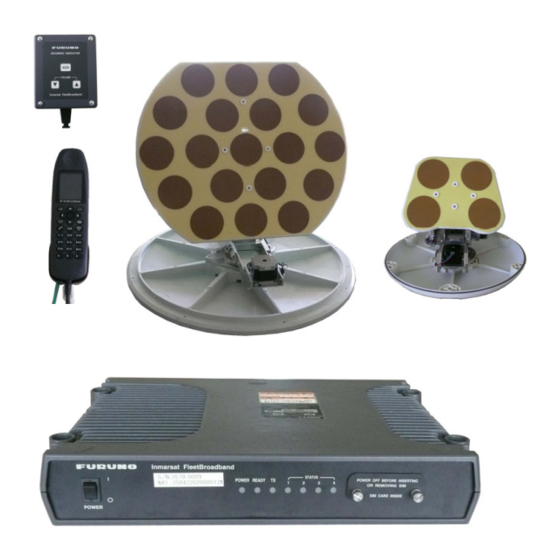
Thank you for considering and purchasing FURUNO equipment. Features The FELCOM 250/500 consists of an antenna unit, communication unit, and a handset. The FEL- COM 250/500 provides telephone, facsimile and data services. The main features of the FELCOM 250/500 are: •... -
Page 11: Program Number
GPL or LGPL as published by the Free Software Foundation. Please access the following URL if you need source codes: https://www.furuno.co.jp/contact/cnt_oss.html This product uses the software module that was developed by the Independent JPEG Group. -
Page 12: System Configuration
SYSTEM CONFIGURATION Antenna unit FB-1500 (FELCOM 500) FB-1250 (FELCOM 250) IP Handset LAN(4) FB-8000 Communication unit FB-2000 Incoming indicator FB-3000 TEL(4) 12-24 VDC AC-DC AC100-115/ Network Equipment Power supply (See Caution on next page.) 200-230V PR-240 G3 facsimile Analog telephone... - Page 13 Caution when connecting shipboard network to FELCOM 250/500 If the FELCOM 250/500 is connected to a shipboard network that has a data monitoring system or the like, the FELCOM 250/500 can become unstable when the equipment in the network trans- mits large volumes of broadcast packets.
- Page 14 SYSTEM CONFIGURATION This page is intentionally left blank.
-
Page 15: Basic Operation
BASIC OPERATION Communication Unit and Handset overview 1.1.1 Communication unit Power switch SIM card slot Inmarsat FleetBroadband STATUS POWER OFF BEFORE INSERTING POWER READY ― OR REMOVING SIM SIM CARD INSIDE ○ ○ POWER Status lamps POWER: Lights green when power is on. READY: Lights green when a satellite is being tracked. - Page 16 1. BASIC OPERATION Number Function • Opens the [Sound] menu. • Softkey (Lower left menu item button) • Opens the Contacts screen. • Softkey (Lower right menu item button) • Moves the cursor up. • Increases the volume. • Moves the cursor down. •...
-
Page 17: Sim Card
1. BASIC OPERATION SIM Card Note: The FELCOM 250/500 uses only Inmarsat Fleetbroadband compatible SIM cards. Individual user information is stored on the SIM card. The system reads information when the SIM card is inserted. The user registration number is saved on the SIM card, and it is possible to transmit with different SIM cards from one terminal. -
Page 18: Power On/Off
1. BASIC OPERATION Power On/Off How to turn on The POWER switch on the front panel of the Communication Unit switches all units of the FELCOM 250/500 terminal on/off: • IP Handset • Communication Unit • Antenna Unit • Incoming Indicator (option) 1. - Page 19 1. BASIC OPERATION 5. Press the Enter key to display the PIN code input screen. 6. Enter the 4- to 8-digit SIM PIN code, and press the Enter key. 7. Press the key. If the PIN code is entered correctly, the idle screen appears on the handset. If en- tered wrong, the message “PIN code is invalid”...
-
Page 20: Screen Layout
1. BASIC OPERATION Handset and web software operational ability The following operations are possible using the handset and Web software: Item Handset Web Software Phone Contacts SMS (Short Message Service) Internet Handset settings Yes (possible with SIP client setting, net- work setting only) Communication Unit settings Screen Layout... -
Page 21: Basic Operation Of The Handset
1. BASIC OPERATION Basic Operation of the Handset 1.5.1 Main menu The handset main menu has 9 items: [Web], [SMS], [SysMsg], [Display], [Contacts], [Sound], [Device], [Setting], and [Info]. 1. At the idle screen, press the Enter key to open the main menu. Cursor (Light-blue highlight) Select with the corresponding key... - Page 22 1. BASIC OPERATION 4. In the selected menu, press to choose a menu item, and press the Enter key to open the item. Or press the corresponding number key for that item. The item screen appears. As an example, the [Font size] menu is shown below. 5.
-
Page 23: How To Input Characters
• If the cursor is on a character, press to in- sert a line break. Example of text input For example, to enter "furuno" at the text input screen, do the following: Available character count Input mode abAB: Alphabet... -
Page 24: How To Edit Text
1. BASIC OPERATION 1.5.3 How to edit text Edit text at the text input screen. How to correct text 1. At the text input screen, put the cursor at the beginning of the text to correct. 2. Press the CLR key. One character erases. Note: To erase all characters to the right of the cursor, press and hold the CLR key down. - Page 25 1. BASIC OPERATION How to paste text Paste text from the clipboard into a message. 1. Move the cursor to the position to paste the text. 2. Press the key to open the sub menu. 3. Press the 3 key to select [Paste]. The latest item is at the top of the list.
-
Page 26: Data Connection Using Web Software
1. BASIC OPERATION 4. To delete one item, press 2 [Delete]. To delete all items press 3 [Delete all]. One of the following confirmation screen appears: [Delete] selected [Delete all] selected 5. Press to select [Yes], and press the Enter key. When complete, the message "Deleted"... -
Page 27: Password
1. BASIC OPERATION 2. Click [Data connection] in the sub menu to show the data connection display. 3. Click the [Connect] button of the service to use. When connecting, the message "Now connecting..." is displayed. When connect- ed, the message "***connection success." appears. 4. - Page 28 1. BASIC OPERATION Password Password Update Log pass- When opening logs. Refer to Soft- word *1 paragraph 5.9.1. ware Administrator When logging in as administrator. Refer to password*1 paragraph 6.1.13. SMS pass- When opening SMS top menu. Refer to paragraph 6.1.13. *1, *2 word extension line...
-
Page 29: Handset Operations
HANDSET OPERATIONS Handset You can call someone on land or ship-to-ship from the handset. This unit allows the handset to be used at the same time as the internet. 2.1.1 How to make a call There are three methods to make a call: 1) Enter the number (or short dial number) of the party to call. - Page 30 XXXXXX Note: To make a telephone call from land to the Inmarsat Terminal FELCOM 250/500, dial the identification code of the telephone carrier, [870] (ocean area code) then the Inmarsat number.
- Page 31 2. HANDSET OPERATIONS How to place a call from the History list A number can be dialed directly from the outgoing and incoming call history list. Up to 20 calls can be stored in each history list. When the 21st call occurs, the oldest logged call is deleted from the list.
- Page 32 2. HANDSET OPERATIONS Operations from the submenu of the History screen At the incoming or outgoing history screen, press the key to open the submenu. Outgoing call Invalid Message creation (see 2.3.2) Contact entry (see 2.2.2) Delete individual history Delete all history Number displayed Number hidden How to call from the Contacts list...
-
Page 33: Operation During Communication
2. HANDSET OPERATIONS Save location icon Name Telephone number 4. Press to dial the number. 2.1.2 Operation during communication How to adjust the volume Adjust the volume of the conversation as follows: 1. During a conversation, press to display the Receive volume screen. 2. -
Page 34: How To Receive A Call
2. HANDSET OPERATIONS How to answer an incoming call during a conversation If another call is received during conversation, perform the following: 1. To answer the call, press the key. To disregard the call, press the key. Then, the incoming caller is rejected and a conversation continues. 2. -
Page 35: Call Forwarding
2. HANDSET OPERATIONS 3. When conversation is finished, press the key to complete the call, or place the handset on the cradle. The communication time appears for 3 seconds and then the idle screen returns. Note 1: If the called party does not answer, a notice appears. Further the missed call icon appears. -
Page 36: Contacts List
2. HANDSET OPERATIONS Contacts List Frequently called numbers can be saved in the Contacts list for easy access when phoning or sending an SMS. Save the Contacts list to the handset, the communication unit or the SIM card. The Handset can store 50 contacts. To commonly use a contact with multiple handsets, save it to the contact list in the communication unit or SIM card. -
Page 37: How To Save A Telephone Number From History To Contacts
2. HANDSET OPERATIONS 9. Assign a short dial number to the contact if required then press the Enter key. Short dial numbers must be two digits and can range from [00] to [99]. The hand- set is able to store 50 short dial numbers. 10. -
Page 38: How To Search The Contacts List
2. HANDSET OPERATIONS Note 2: To register a number entered from the idle screen to the Contacts, press the key, then 2 to select [Save num.]. The remainder of the procedure is the same as that from step 5 in this procedure. 2.2.3 How to search the Contacts list This section shows you how to search the handset, communication unit and SIM card... -
Page 39: How To Edit A Contact
2. HANDSET OPERATIONS 2.2.4 How to edit a contact You can edit a contact from the handset in which the contact is registered. Contacts saved to the communication unit and SIM card cannot be edited from a handset (refer to paragraph 5.5.3). 1. - Page 40 2. HANDSET OPERATIONS Delete individual contact 1. At the idle screen, press the key to open the Contacts. 2. With [Hndset] selected, press to select the contact to delete. 3. Press the key to open the submenu. 4. Press 4 to select [Delete]. 5.
-
Page 41: Sms
2. HANDSET OPERATIONS The Short Message Service (SMS) allows you to send and receive SMS messages to similarly equipped mobile phones and Inmarsat terminals. An SMS message can have up to 160 alphanumeric characters. Note: Not all mobile phone carriers permit reception and transmission of SMS mes- sages to Inmarsat terminals. -
Page 42: How To Send An Sms Message
2. HANDSET OPERATIONS 2.3.2 How to send an SMS message You can send a message with a maximum of 160 characters (alphanumeric, symbols) to a communication terminal that has SMS capability. 1. At the idle screen, press the key to show the [SMS] menu. 2. -
Page 43: How To View A Received Message
2. HANDSET OPERATIONS 7. Press the key to open the submenu. XXXXXXXXXXXX Name appears here if telephone number is registered in Contacts. 8. Press 1 to select [Send] to send the message. The message "Sending..." appears while the message is being sent. When completed, the message "Sent." appears. Note 1: To save a message to the [Draft] box without sending the message, press 2 instead of 1 to select [Save]. -
Page 44: Message Boxes
2. HANDSET OPERATIONS 1. With [New SMS] selected, press the Enter key. The Inbox displays. Message count XXXXXX : Unread : Read 2. Press to select the message, and press the Enter key. Read status icon Date/month and time received XXXXXXXXXX Sender Name displays if sender is... - Page 45 2. HANDSET OPERATIONS Received messages box Sent messages box Draft messages box Recycle bin *1: Unread message count displays in brackets. *2: Unsent message count displays in brackets. How to move a message to the recycle bin You can move the messages from any box into the Recycle Bin. Messages can be moved individually or all at once.
- Page 46 2. HANDSET OPERATIONS 3. Press 3 to select [Sort]. Sent box/Draft box Inbox 4. Press to select sort method. Date: Sort messages by date received, sent, or created. Unread: Sort messages by unread/read status. Sender name: Sort messages by sender name (A-Z), number (0-9), and symbol. Senders that are not saved in Contacts display at the top of the list.
- Page 47 2. HANDSET OPERATIONS 4. To move an individual message, press 1 to select [Move]. To move all messages, press the 2 key to select [Move all]. 5. Press to select the box where to move the message, and press the Enter key.
-
Page 48: How To Use Received Messages
2. HANDSET OPERATIONS 2.3.5 How to use Received messages Received messages can be replied to and forwarded. You can also use received mes- sages to telephone the sender of the message, add a sender to Contacts, and copy the text of the message. How to reply to a message Do the procedure below to reply to a received message. - Page 49 2. HANDSET OPERATIONS How to call the sender of a message Call the sender of a received SMS as follows: 1. Open the Inbox and open the message to call sender from. 2. Press the key to open the submenu. 3.
-
Page 50: How To Use Sent Messages
2. HANDSET OPERATIONS 2.3.6 How to use Sent messages Messages in the Sent box can be edited and re-sent. You can also use sent messages to telephone the sender of a message, add a sender to Contacts and copy text of a message. -
Page 51: How To Use Draft Messages
2. HANDSET OPERATIONS 2.3.7 How to use Draft messages Un-sent messages, and failed transmission messages are saved in the Draft box. It is possible to edit, resend, copy text, telephone the sender, and save address to Con- tacts. How to edit and send messages Edit and send a message in the Draft box as follows: 1. -
Page 52: How To Use Url And Phone Numbers Within Messages
2. HANDSET OPERATIONS 2.3.8 How to use URL and phone numbers within messages If a phone number is included in a message, it can be copied, called, replied to (by SMS), and added to Contacts. If a URL is included in a message, it can be viewed, added to Favorites, and copied. - Page 53 2. HANDSET OPERATIONS 1. Open the message with the included URL. 2. Press to select the URL. The URL is highlighted in light blue. Characters which are recognized as URL address 3. Press the Enter key to display the submenu. 4.
-
Page 54: Web
2. HANDSET OPERATIONS You can view web pages on the handset by using Standard IP (Best effort) packet communications service. Service charge is based on the amount of data volume, not connection time. Note: The handset can start from Standard IP packet service. However, when using Streaming IP data packet service with the Web Software, the handset uses streaming IP service. -
Page 55: How To View A Web Page
2. HANDSET OPERATIONS How to disconnect from the internet Do the following to disconnect from the internet. This operation disconnects all service types (Standard IP Packet, Streaming IP packet). 1. At the idle screen, press the key to open the [Web top] menu. 2. - Page 56 2. HANDSET OPERATIONS Direct input of URL 1. At the idle screen, press the key to open the [Web top] menu. 2. Press 1 to select [Input URL]. Most recently input URL appears here. 3. Press the Enter key to show the URL input screen. 4.
- Page 57 2. HANDSET OPERATIONS How to open a URL from the Input history screen This procedure is invalid if the input history is empty. 1. At the idle screen, press the key to open the [Web top] menu. 2. Press 1 to select [Input URL]. 3.
- Page 58 2. HANDSET OPERATIONS How to view URL from the Favorite list If there are no items on the Favorite list, the message "no list" displays, and the fol- lowing procedure is invalid. 1. At the idle screen, press the key to open the [Web top] menu. 2.
-
Page 59: Operations While Viewing A Web Page
2. HANDSET OPERATIONS 2.4.3 Operations while viewing a web page While viewing a web page, press the key to open the submenu. The following operations are available: • 1 (Back): Return to previous web page (if data is in cache). •... -
Page 60: Favorite List
2. HANDSET OPERATIONS 2.4.4 Favorite list How to add a URL to the Favorite list while viewing the list Add often-accessed web pages to the Favorite list for easy viewing. The Favorite list stores 10 URLs. Do the following to register pages to the favorite list: Note: If there are already 10 pages in the Favorite list, it is not possible to add another without deleting one. - Page 61 2. HANDSET OPERATIONS How to delete an item from the Favorite list You can delete one item, or all items, from the Favorite list as follows: 1. Open the Favorite list. To delete one item, go to step 2, and to delete all items, go to step 3.
- Page 62 2. HANDSET OPERATIONS This page is intentionally left blank. 2-34...
-
Page 63: Settings For Handset
SETTINGS FOR HANDSET This chapter describes the menus [Sound], [Display], [SMS], [Web], and [Settings]. Also described are system messages from connected equipment, list of connected equipment, and how to display various information. Sound Menu The [Sound] menu sets options for internal and external phones, message notification for SMS messages and system messages, key beep, and microphone volume. -
Page 64: How To Adjust Keypad Tones Volume
3. SETTINGS FOR HANDSET How to set the ring pattern 1. In the [Sound] menu, press either the 1, 2, 3, or 4 key for the following: 1: External phone incoming notification pattern 2: Internal phone incoming notification pattern 3: SMS message notification pattern 4: System message notification pattern 2. -
Page 65: Display Settings
3. SETTINGS FOR HANDSET Display Settings Change font size, LCD backlight, and key backlight from the [Display] menu. 1. At the idle screen, press the Enter key to open the main menu. 2. Press to select the [Display] icon, and press the Enter key to shown the [Dis- play] menu. -
Page 66: How To Change Lcd Brightness And Backlight On Time
3. SETTINGS FOR HANDSET 3.2.2 How to change LCD brightness and backlight ON time Change the LCD brightness and backlight ON time as follows: Brightness 1. In the [Display] menu, press 2 to select [LCD] to show the [LCD] menu. 2. -
Page 67: How To Adjust The Keypad Backlight
3. SETTINGS FOR HANDSET 3. Press to select either [Always] or [Specify] and press the Enter key. [Always]: Keep the LCD light always on. Go to step 6. [Specify]: Enter a time limit for the backlight. If there is no key operation during the time limit, the LCD back- light automatically turns off. -
Page 68: Sms Settings
[OFF]: A signature is not automatically added to SMS messages (go to step 4). 3. Enter the signature text (maximum 156 characters) and press the Enter key. For example, if “FURUNO” is entered as the signature, the sent message looks like the one shown below. -
Page 69: Web Settings
3. SETTINGS FOR HANDSET 3.3.2 How to activate the SMS password To activate the SMS password, do as follows. 1. In the [SMS settings] menu, press 2 to select [Password]. 2. Press to select [Save password]. 3. Press the Enter key to delete the checkmark [ ] from the checkbox. 4. -
Page 70: How To Change Web Page Display Zoom
3. SETTINGS FOR HANDSET 3.4.2 How to change web page display zoom You can change the display zoom factor to enlarge small print. 1. In the [Web settings] menu, press 2 to select [Zoom level] to show the[ Zoom level] screen. -
Page 71: Advanced Settings
3. SETTINGS FOR HANDSET 2. Press to select [Normal], [Just-fit] or [Smart-fit]. 3. Press the Enter key to select. 4. Press the key to close the menu. 3.4.4 Advanced settings Display image, Javascript and Popup window options can be set in Advanced Set- tings. -
Page 72: How To Set Time Out
3. SETTINGS FOR HANDSET 3.4.5 How to set time out Set the period of no activity before the handset disconnects from the Web. The default setting is 30 seconds. To change the Timeout setting, do the following: 1. In the [Web settings] menu, press 5 to select [Timeout] to show the [Timeout] screen. -
Page 73: Individual Settings Menu
3. SETTINGS FOR HANDSET Individual Settings Menu Basic (settings), Network, SIP, Operation Password, Initialization and Self test can be accessed from the [Settings] menu. Initialize and Self test are explained in Chapter 7. The communication unit contains the following server functions: •... - Page 74 3. SETTINGS FOR HANDSET 2. Press 3 to select [Clock] and show the [Clock settings] screen. 3. Select [NTP server] then press the Enter key. 4. Press to select Manual then press the Enter key to show the NTP server IP address input screen.
- Page 75 3. SETTINGS FOR HANDSET How to set call and message notifications Set the notifications for missed call and received messages at the [Notify] screen. No- tifications can be set to appear as icons ( ) on the upper part of the screen and as a window message, or as icons with no window message.
- Page 76 3. SETTINGS FOR HANDSET How to set Quick Off hook When quick off hook is set to ON, to take the handset off the cradle has the same ef- fect as to press the key (phone answers automatically). 1. In the [Settings] menu, press 1 to select [Basic] to show the [Basic] menu. 2.
-
Page 77: Network Settings
3. SETTINGS FOR HANDSET 3.5.2 Network settings Network settings can be set automatically or manually. 1. In the [Settings] menu, press 2 to open the [Network] menu. You are asked to en- ter the operation password. 2. Press the Enter key. 3. - Page 78 3. SETTINGS FOR HANDSET If you select the [DHCP] at the step 7, the [Manual set.] screen appears. Go to step 16. Static IP factory default settings 9. With the [IP address] field selected, press the Enter key. 10. Enter the IP address for this unit, and press the Enter key. 11.
-
Page 79: Sip Settings
3. SETTINGS FOR HANDSET 19. With the [DNS (Primary)] field selected, press the Enter key. 20. Enter the IP address of the primary DNS server and press the Enter key. 21. Press to select the [DNS (Secondary)] field, and press the Enter key. 22. -
Page 80: How To Change Operation Password For The Handset
3. SETTINGS FOR HANDSET *1: To change both extension number and SIP password at the [Client set.] menu, you must also change a setting of the Web software at the SIP server. (See page 6-4.) The telephone functions cannot be used if the settings for SIP client and SIP server are different. -
Page 81: System Messages
3. SETTINGS FOR HANDSET System Messages If an alarm occurs in a unit connected in the same network, the handsets sounds an alarm tone and an alert information window displays. The alarm icon ( ) also ap- pears at the status bar on the upper part of the screen. 1) In the alert information window, select [New SysMsg] and press the Enter key. -
Page 82: How To Show Tcp/Ip, Sip And Software Version Information
3. SETTINGS FOR HANDSET How to Show TCP/IP, SIP and Software Version information Do as follows to see TCP/IP, SIP and software version information. 1. At the idle screen, press the Enter key to show the main menu. 2. Press , then to select the [Info] icon and press the Enter key to show the [In- formation] menu. -
Page 83: Optional Devices
OPTIONAL DEVICES Analog Telephone FC755D1 RING TONE lamp: Lights when calling; blinks when holding a call. ONE-TOUCH DIAL keys: Register/dial abbreviated dialing numbers. Change the ring tone and ring pattern. Display: Shows number being dialed, settings, etc. RCV lamp: Blinks when call is received. VOLUME key: Adjusts volume of ring, or volume of receiver when speaking. -
Page 84: Fax (Fax-2820/Fax-2840)
FAX number. When replying to a FAX, be sure to ask the sender for their FAX number. Note 3: When you send a fax from FELCOM 250/500 to FELCOM 30/50/70, always use a 3.1 Khz audio service number. -
Page 85: Web Software
WEB SOFTWARE The Web software makes a connection to Internet, adjusts the Communication Unit settings, creates SMS messages, and creates/edits the Contacts list. Connect the Communication Unit to a PC to use the Web software. The Communication Unit works with the following web browsers: ®... -
Page 86: Screen Explanation
5. WEB SOFTWARE Screen Explanation The screen is divide into several areas. Administrator login/ logout button. Refer to 5.9.1, 6.1.1 Menu bar Status area System message area Sub menu area Information area See “IMPORTANT NOTICES” (page i). Status area The status area displays the reception signal level, ship position information, date and time. - Page 87 5. WEB SOFTWARE System message area Error and Warning messages are displayed in red letters in the System message area (See section 7.6). Affected area is displayed in parentheses Icon : SIM card related warning message : Error message unrelated to SIM card message : Warning message unrelated to SIM card Menu bar The menu bar contents are different when you are logged in or if you are logged out.
-
Page 88: Status Monitor
5. WEB SOFTWARE Status Monitor The Status monitor displays satellite tracking status, communication status, ship po- sition information, Communication Unit internal temperature, and error information. Data is refreshed every five seconds. If the Status monitor is not displayed, do the fol- lowing to view: See “IMPORTANT NOTICES”... - Page 89 5. WEB SOFTWARE Item Description Displays Streaming IP packet session volume. The total for all Connection groups is shown if logged in as Administrator. Ship position information Using GPS Displays GPS in use. Internal, External, No fix (GPS data invalid), No data (no GPS da- Latitude Displays ship latitude.
-
Page 90: Data Connection
5. WEB SOFTWARE Data Connection There are two types of IP packet communication services: Connection Payment Service Description speed method Standard IP Speed of the com- • Max. 284 Fee based • E-mail packet com- munication service kbps on amount •... - Page 91 5. WEB SOFTWARE How to connect to the internet Follow the procedure shown below to connect to the internet. Note 1: You cannot connect to the internet if the main display of the web software shows “Data connection No permission”. Note 2: You can connect to the internet via PPPoE.
- Page 92 5. WEB SOFTWARE In the above connection list, Standard IP Packet Data Connection Service is connected first. • In the [Status] field, "Not connected" changes to "Connected" (displays in green). • The display in the [Operation] field changes from "Connect" to "Disconnect". 6.
-
Page 93: Contacts
5. WEB SOFTWARE Contacts Like the handset, you can add, edit and delete contacts from the Web software. Use the Web software to save contacts to the Communication Unit or SIM card. Media Maximum savable address count Communication Unit 150 addresses SIM card Different with SIM card type 5.5.1... -
Page 94: How To Arrange The Contacts List
5. WEB SOFTWARE 5.5.2 How to arrange the Contacts list How to sort the Contacts list You can display your contacts in ascending/descending order of ASCII code order. 1. Click [Contacts] in the menu bar. 2. Click the [Name] field at the very top of the Contacts list. A ) symbol is displayed beside [Name]. -
Page 95: How To Edit Contacts
5. WEB SOFTWARE 5.5.3 How to edit contacts To edit the name or number of a contact, do the following. 1. Click [Contacts] in the menu bar. 2. Select a contact to edit, and click the [Edit] button on the right side of the contact. 3. -
Page 96: How To Copy And Move Contacts Data
5. WEB SOFTWARE 5.5.5 How to copy and move contacts data You can copy or move contacts between the handsets, communication unit and the SIM card. The communication unit acts as a hub for the data transfer. Administrator level (or higher) login is required to access the Contacts list menu and the Copy/Move function. -
Page 97: Sms (Short Message Service)
5. WEB SOFTWARE SMS (Short Message Service) You can create SMS messages from the Web software or the handset. Messages are limited to 160 characters. For the Web software, messages are limited to 70 charac- ters in Japanese, Chinese, French, Russian, Spanish or Arabic due to the Unicode support. -
Page 98: How To Send An Sms Message
5. WEB SOFTWARE 5.6.2 How to send an SMS message You can send an SMS message to the terminal enabled SMS. 1. Click [SMS] in the menu bar to show the SMS top screen (Inbox). 2. Click [Create SMS] in the sub-menu to show the Create SMS screen. Entry Entry Maximum allowable character count... -
Page 99: How To Review A Received Message
5. WEB SOFTWARE 5.6.3 How to review a received message Received messages are saved to the Inbox. 1. Click [SMS] in the menu bar to show the SMS top screen (Inbox). Unread mes- sages are displayed in bold type. Inbox message count (unread message count) 5 (3) XXXXXXXXX XXXXXXXXX... -
Page 100: Message Boxes
5. WEB SOFTWARE 5.6.4 Message boxes There are four message boxes: [Inbox], [Sent], [Draft] and [Recycle bin]. When the amount of messages is more than the maximum, the oldest message in each mes- sage box is automatically erased from all boxes. Message type Maximum Amount [Inbox]... - Page 101 5. WEB SOFTWARE How to move messages from Recycle Bin to another box Move a single message, multiple messages, or all messages in the [Recycle bin] to another box. 1. Click [SMS] in the menu bar. 2. Click the [Recycle bin]. The following screen appears: Recycle bin message count Listbox XXXXXXXXX...
-
Page 102: How To Use The Sent Box
5. WEB SOFTWARE 5.6.5 How to use the Sent box Use the Sent message box to edit and resend sent messages. 1. Click [SMS] in the menu bar. 2. Click [Sent] to show the contents of the Sent box. Sent box message count XXXXXXXXX XXXXXXXXX XXXXXXXXX... -
Page 103: How To Use The Draft Box
5. WEB SOFTWARE 5.6.6 How to use the Draft box You can save un-sent messages to the Draft box to edit or send later. 1. Click [SMS] in the menu bar. 2. Click [Draft] to show the contents of the Draft box. Unsent message count XXXXXXXXX XXXXXXXXX... -
Page 104: How To Set The Signature And Password
5. WEB SOFTWARE 5.6.7 How to set the signature and password You can set up the SMS signature and password in the SMS Settings screen. Signature Add a signature to all SMS messages automatically as follows: 1. Click [SMS] in the menu bar. 2. -
Page 105: Sim Card Settings
5. WEB SOFTWARE SIM Card Settings You can update SIM card information and change PIN code. How to update SIM card information Depending on SIM card type, it is necessary to enter a PIN code when power is turned on. It is possible to update the SIM card information. 1. -
Page 106: Manual Satellite Search
5. WEB SOFTWARE Manual Satellite Search FELCOM 250/500 is set to automatically search and track the closest satellite. It is also possible to manually search for a satellite. 1. Click [Main] in the menu bar. 2. Click [Satellite search]. See the figure below for the service area for FleetBroad- band. -
Page 107: Log Displays
5. WEB SOFTWARE Log Displays You can display four logs: Registration log, Voice call log, Data connection log, and Event log. When the storage capacity of a log is reached, the oldest entries are erased in order. Capacity for entries No. -
Page 108: How To View The Registration Log
5. WEB SOFTWARE 5.9.2 How to view the Registration log The Registration log displays a list of all satellite registrations. To view the Registration log, do the following: 1. Click [Log] in the menu bar. 2. Click [Registration log]. The following Registration log screen appears: Registration date and time Registered satellite ID Voice communication... -
Page 109: How To View The Voice Call Log
5. WEB SOFTWARE 5.9.3 How to view the Voice call log Do the following to view the Voice call log: 1. Click [Log] in the menu bar. 2. Click [Voice call log]. The following Voice call log screen appears: 0081XXXXXXXXXX E7005 +81XXXXXXXXX +81XXXXXXXXX... - Page 110 5. WEB SOFTWARE 5. To display the detailed log, click the [Detail] button. To return to the Voice call log, click the [Back] button. +81XXXXXXXXX Item Description Date Displays the date when the communication starts. Service Displays the communication service. Direction Displays the communication direction.
-
Page 111: How To View The Data Connection Log
5. WEB SOFTWARE 5.9.4 How to view the Data connection log To view the Data connection log do the following: 1. Click [Log] in the menu bar. 2. Click [Data connection log] to show the Data connection log screen. 1) Date of start of communications 2) Communication time (If currently connected, “Connected”... - Page 112 5. WEB SOFTWARE 4. To arrange the log in ascending or descending order, do the following: 1) At the top of the log list, click either [Date], [Duration], [KBytes], [Service], [La- bel], or [Code]. appears beside the selected item. 2) Click the item again to change between (ascending) or (descending) or- der.
-
Page 113: How To View The Event Log
5. WEB SOFTWARE 5.9.5 How to view the Event log To view the Event log do the following: 1. Click [Log] in the menu bar. 2. Click [Event log] to show the Event log. Corresponding to the message, the follow- ing [Error], [Warning] or [Notice] indicator appears. -
Page 114: How To Download All Logs
5. WEB SOFTWARE Note 2: The details of an event code can be displayed from the Event log by clicking the event code. To return to the Event log, click the [Back] button. Action 5.9.6 How to Download all logs The logs listed below can be downloaded collectively. -
Page 115: Web Functions
WEB FUNCTIONS This chapter covers how to access Communication Unit settings, and connection in- formation. User must login as Administrator to access these functions. Note: Communication may not be possible if setting are wrong. Settings should be performed by an experienced administrator. Also, be sure to log out after performing settings. -
Page 116: How To Display The Information Screen
6. WEB FUNCTIONS 6.1.2 How to display the Information screen You can view information of GPS, Analog ports, Incoming Indicator, and Serial port in the [Basic] submenu, LAN and PPPoE in the [Network Settings] submenu. 1. Click [Settings] in the menu bar. The Settings sub menu is displayed on the left hand side. - Page 117 6. WEB FUNCTIONS ber. To use that number, go to step 6. To change the extension number, go to step 5. 5. Change the extension number (1000 - 9999) in the [Number] box. 6. Enter the extension number password in the [Password] box. A maximum of eight characters (capital letters only) can be entered.
- Page 118 6. WEB FUNCTIONS Usage Input Example Remarks Register telephone +81798631131# Forbid outside calls to other than number of shore office. the phone number registered here. Register only country Permit calls only to Japan. number (Japan for ex- ample). Register the number ex- Forbid outside calls other than clusive use of pre-paid those made with a pre-paid card.
-
Page 119: Group Settings
6. WEB FUNCTIONS 6.1.4 Group settings Register numbers to a group and make a group call (internal only). For example, add numbers 1001-1010 to group 9000, and all numbers from 1001-1010 can be called at the same time. The first recipient to answer receives the call, and the other numbers stop ringing. -
Page 120: Access Code Settings
6. WEB FUNCTIONS • "This number has already been registered": The number already exists. 9. Click the [OK] button. The Group screen is displayed with the new group. How to edit a group 1) Display the Group screen. 2) Select the group number to edit, and click the [Edit] button. 3) Edit the group number, name or members. - Page 121 6. WEB FUNCTIONS 4. Click the [Add code] button. 5. Enter the access code in the [Access code] field (10000 - 99999). 6. Enter a caller name in the [Name] field (10 characters at the maximum). Only alphabet characters, “_” and “-” can be entered. The name entered in this field appears in the “Caller“...
-
Page 122: Pbx Settings
6. WEB FUNCTIONS 6.1.6 PBX settings How to set the ring duration time Set the ring duration time of the terminal checked ( ) in the [V1] (or [F1]) box of the PBX settings/ Extension screen. (Not available for the multi voice and the extension.) 1. -
Page 123: How To Set Internal Call Routing
Completed." appears. 9. Click the [OK] button to erase the message. When a voice call is received, the FELCOM 250/500 plays guidance to the calling par- ty. Then, the calling party inputs an extension number. The call is then transferred to that number. -
Page 124: Lan Settings
6. WEB FUNCTIONS 6.1.8 LAN settings The LAN Settings must be performed by the network manager. How to set the LAN IP address Click [Settings] in the menu bar, the [Network settings], [LAN] and [IP address] in the sub-menu. The following screen appears. Item Description Own IP address... - Page 125 6. WEB FUNCTIONS DHCP lease information screen No. of entries made / No. of entries possible Item Description Delete button Delete the item which has a checkmark. Add lease button Enter new lease information. The screen for entry of new lease in- formation appears.
- Page 126 6. WEB FUNCTIONS Routing information settings Click [Settings] in the menu bar, [Network settings], [LAN] and [Routing] in the sub- menu. The following screen appears. No. of entries made/ No. of entries possible Item Description Delete button Delete item having a checkmark [ ]. Items which the [Status] is [Dynamic] cannot be deleted.
- Page 127 6. WEB FUNCTIONS Item Description Add button Register information entered. Return to routing information setting screen. Save button Save information entered. Return to routing information setting screen. Cancel button Return to routing information setting screen. RIP settings Click [Settings], [Network settings], [LAN] and [RIP] in the menu bar. The following screen appears.
-
Page 128: Wan Settings
6. WEB FUNCTIONS 6.1.9 WAN settings The network equipment (PC, etc.) connected to the FELCOM can be divided into mul- tiple groups to get independent data connection for each group. For example, you can have a group for office use and a group for private use. In this way crew members can pay for their own personal communication charges, making it unnecessary to limit communications. - Page 129 6. WEB FUNCTIONS Group setting screen (basic) Click [Basic] on the Group setting screen to show the basic setting screen. This screen is where you make a connection list. No. of connections/No. of connections available (incl. other groups) *: Connection list No.
- Page 130 6. WEB FUNCTIONS Entry screen/Edit screen Creation screen Edit screen Item Description Group Display group name. Service Select service to use. (Standard data, 8kbps Streaming, 16kbps Streaming, 32kbps Streaming, 64kbps Streaming, 128kbps Stream- ing, 256kbps Streaming*) The topmost item on the connection list (Standard) cannot be changed.
- Page 131 6. WEB FUNCTIONS Entry screen/Edit screen Entry screen Edit screen Item Description Group Display group name. User Enter, change IP address (127.0.0.1, 255.255.255.255; must be differ- ent from IP address of communication unit). Note: if the IP addresses are the same, only one group can be regis- tered.
- Page 132 6. WEB FUNCTIONS Item Description DNS server • Choose the method for obtaining the DNS server address (Global) (Automatic, Manual). • If Manual is selected, enter the address of the Primary DNS server (IPv4 address). • If Manual is selected, enter the address of the Secondary DNS Server (IPv4 address).
- Page 133 6. WEB FUNCTIONS Group setting screen (Firewall) Click [Firewall] on the Group setting. Use this screen to block unwanted communica- tions. Set the screen according to application and system. Item Description Prohibit the routing of Check to prohibit NBT and Microsoft-DS. The default setting is NBT &...
- Page 134 6. WEB FUNCTIONS Entry screen/Edit screen Newly register screen Editing screen Item Description Group Show group name. Action Select actions from [Pass] and [Block]. Domain name Enter and edit the domain name to block. If “*” is entered, access to all the domains will be blocked.
- Page 135 6. WEB FUNCTIONS Group setting screen (IP filter) Click [IP filter] on the Group setting screen to show the IP filter setting screen. This screen lets you prevent unwanted communications. Set the screen according to appli- cation and system. No. of registrations/No. of registrations available Item Description Delete button...
- Page 136 6. WEB FUNCTIONS Item Description DST. address Enter, edit destination address (IPv4 address). From address Enter, edit source address (IPv4 address). Protocol Select protocol (ALL, ICMP, Any, TCP/UDP, TCP/UDP(NAPT)). • If [Protocol] is [Any], enter the protocol number (1-255). • If [Protocol] is [TCP/UDP] only, select TCP/UDP, TCP, UDP from list box.
- Page 137 6. WEB FUNCTIONS VPN pass-through screen Click [VPN pass-through] on the group setting screen to show the VPN pass-through setting screen. Set the screen according to your system. Item Description IPSec Place a [ ] by IPSec pass-through to activate. PPTP Place a [ ] by PPTP pass-through to activate.
-
Page 138: Pppoe Settings
6. WEB FUNCTIONS 6.1.10 PPPoE settings The FELCOM can connect (dial-up connection) to the internet via PPPoE. With the Web software and PC set up for PPPoE, the dial-up application directly controls con- nection and disconnection of the data line. (It is not necessary to boot the Web soft- ware to connect to the internet.) The PPPoE settings must be done by the network administrator. - Page 139 6. WEB FUNCTIONS Item Description (Confirmation) Enter PPPoE password. Service Select the service to use, among Standard, 8kbps, 16kbps, 32kbps, 64kbps, 128kbps, 256kbps IP address for PPPoE Display IP address of PPPoE server. Enter IP address of PPPoE client (*.*.*.0,*.*.*.255. Do not set same IP address as communication unit.) Add button Register data.
- Page 140 6. WEB FUNCTIONS Session setting screen (TCP/IP) Click [TCP/IP] on the session setting screen to show the TCP/IP setting screen. Set the connection name for various provider services. Item Description • Use connection destination registered in the SIM card (checkmarked [ ] items). •...
- Page 141 6. WEB FUNCTIONS Session setting screen (Connection) Click [Connection] on the session setting screen to show the Connection setting screen. Set the connection name for various provider services. Item Description Auto disconnection • Automatically disconnects the session line when below two conditions are met.
- Page 142 6. WEB FUNCTIONS Group setting screen (DNS filter) Click [DNS filter] on the session setting screen to show the DNS filter setting screen. This screen lets you prevent unwanted communications. Set the screen according to application and system. No. of registrations/No. of registrations available Item Description Delete button...
- Page 143 6. WEB FUNCTIONS Change priority of DNS filter screen Item Description Raise the priority of selected item. Lower the priority of selected item. Apply button Apply the priority setting. Go back to DNS filter setting screen. Cancel button Go back to DNS filter setting screen. Access list screen xxx.xxxx.com xxx.xxxx.com...
- Page 144 6. WEB FUNCTIONS Item Description DST. address Show the recipient address (if not set, “anywhere” is shown). From address Show the sender address (if not set, “anywhere” is shown). Protocol Display the protocol. Area • If [Protocol] is [Any], displays the protocol number. •...
- Page 145 6. WEB FUNCTIONS Change priority of IP filter screen Item Description Raise priority. (Right button: inoperative) Lower priority. (Right button: inoperative) Apply button Save entered information. Return to the IP filter setting screen. Cancel button Restore previous IP filter settings and return to the IP filter setting screen.
- Page 146 6. WEB FUNCTIONS ® PC settings (for Windows First set PPPoE information on the Web software then set it on the PC. 1. Click the [Start] button, [Settings] (Start menu in case of Classic display), [Control Panel]. 2. Double-click [Network Connections] to show the Network connections dialog box. 3.
- Page 147 6. WEB FUNCTIONS 6. Select [Set up my connection manually] then click the [Next] button. 7. Select [Connect using a broadband connection that requires a user name and password] then click the [Next] button. 8. Enter desired name (ex. FELCOM 500) in the [ISP name] box then click the [Next] button.
- Page 148 6. WEB FUNCTIONS 9. Select [Anyone’s use] or [My use only] as applicable then click the [Next] button. 10. Enter PPPoE user name in the [User name] box. 11. Enter PPPoE password in the [Password] box. 12. Enter PPPoE password again in the [Confirm password] box. 13.
- Page 149 6. WEB FUNCTIONS 16. Click the [Options] button. 2 minutes Note: Keep the default settings of everything in this dialog box, except [Redial at- tempts] and [Time between redial attempts]. 17. Set [Time between redial attempts] to other than two minutes. 18.
- Page 150 6. WEB FUNCTIONS 3. Left-click [Set up a new connection or network]. 4. Select [Connect to the Internet], then left-click [Next]. 5. Left-click [Set up a new connection anyway]. 6-36...
- Page 151 6. WEB FUNCTIONS 6. Select [No, create a new connection], then select [Broadband (PPPoE)], then left- click [Next]. 7. Enter the User name and Password according to the settings made for PPPoE. (See "Entry screen" on page 24). 8. You may rename the connection using the [Connection name] field. Renaming the connection is optional.
- Page 152 6. WEB FUNCTIONS 10. Left-click [Close]. A window similar to the one shown below is displayed. Sample broadband connection status 11. Left-click the Properties button. A window similar to the one shown below is dis- played. Sample broadband connection properties 12.
- Page 153 6. WEB FUNCTIONS ® How to connect to the internet via PPPoE (for Windows ® Connect to the internet with a dial-up application, for example, Internet Explorer 1. Open the dial-up application and the [Dial-up Connection] dialog box appears. Note 1: If the Dial-up connection dialog box does not appear, click [Tools], [Inter- ®...
- Page 154 6. WEB FUNCTIONS 3. Click the [Connect] button to start the data connection. The task bar shows [Con- nected to ***] (*** is the name on the icon for PPPoE connection) if you are con- nected to the internet. 4. To disconnect the data connection, click the icon for PPPoE connection ( ) on the task bar.
-
Page 155: How To Set The Bridge Mode
6. WEB FUNCTIONS 4. Left-click the appropriate PPPoE network connection, then left-lick the [Connect] button which is displayed. A window similar to the one shown below is displayed. 5. Input the PPPoE username and password, then left-click the [Connect] button. How to show the PPPoE status monitor display The PPPoE status monitor display shows the packet communication volume for the current PPPoE session. - Page 156 6. WEB FUNCTIONS 4. Click the [Add bridge] button. 5. Set as follows: Item Description Port • Select LAN port (LAN1, LAN2, LAN3, LAN4). • LAN port already used can not be selected. Connection • Constant connection: Put a [ ] in the checkbox beside [Al- ways on].
-
Page 157: How To Set The Remote Access
6. WEB FUNCTIONS 6.1.12 How to set the Remote access The Remote access lets you access the web menu settings of FELCOM250/500 via internet. Note 1: The following settings are recommended: • Select a port number that is not narmally used. •... -
Page 158: How To Change The Password
6. WEB FUNCTIONS 6.1.13 How to change the password Do the following procedure to change the SMS password, log password, and Admin- istrator password. Write down the password in log so as not to forget the password. If the password is lost, contact the dealer or retail supplier. 1. -
Page 159: How To Forward The Log To A Pc
6. When finished, click the [Apply] button. The message "The CmmUnit will restart automatically after this setting. Continue?" displays. 7. Click the [OK] button. The message "Completed. Please wait a moment for re- starting." displays. 8. Click the [OK] button. FELCOM 250/500 restarts. 6-45... -
Page 160: Device List
6. WEB FUNCTIONS Device List All devices connected to the same network can be displayed. The link setting of auto detected handset and devices registered on device list can be changed with the Web software. 6.2.1 How to detect devices automatically 1. -
Page 161: How To Change The Link Setting In The Device List
6. WEB FUNCTIONS 6.2.2 How to change the link setting in the Device list Handsets, Incoming Indicators, etc., are registered to the Device list, and can be changed with the Web software. Also, equipment is connected to a web server can be manually registered with the Web software. - Page 162 6. WEB FUNCTIONS How to manually register an item on the Device list You can manually register equipment on the web server to the device list. 1. Open the Device list. 2. Click the [Add list] button. Mandatory Mandatory 3. Enter the name in the [Name] field (max. 50 characters). 4.
-
Page 163: How To Save, Load Settings
6. WEB FUNCTIONS How to Save, Load Settings The following web software related settings can be saved. • Main: Search option for Satellite search • SMS: Signature of SMS settings • Settings: All Basic settings • Settings: All PBX settings •... - Page 164 6. WEB FUNCTIONS This page is intentionally left blank. 6-50...
-
Page 165: Maintenance And Troubleshooting
MAINTENANCE AND TROUBLESHOOTING This chapter describes maintenance and troubleshooting procedures to keep the equipment in good condition and restore normal operation in case of trouble. NOTICE WARNING o not apply paint, anti-corrosive ELECTRICAL SHOCK HAZARD Do not open the equipment. sealant or contact spray to plastic parts or equipment coating. -
Page 166: How To Change The Fuse
7. MAINTENANCE AND TROUBLESHOOTING How to Change the Fuse WARNING Use the proper fuse. Use of a wrong fuse can result in damage to the equipment and cause fire. The fuse in the power cable protects the unit from overcurrent. If you cannot turn on the power, check if the fuse has blown. -
Page 167: Communication Unit (Cu) Led Lamps
7. MAINTENANCE AND TROUBLESHOOTING Communication Unit (CU) LED Lamps Inmarsat FleetBroadband STATUS POWER OFF BEFORE INSERTING POWER READY ― OR REMOVING SIM SIM CARD INSIDE ○ ○ POWER POWER STATUS (1 - 4) READY The communication Unit LED lamps indicate the status of the antenna unit and the CU. -
Page 168: Troubleshooting
7. MAINTENANCE AND TROUBLESHOOTING Troubleshooting If you think the equipment is not operating normally, do the checks in the table below to find the possible causes. If repair of the equipment is necessary report the result of the troubleshooting to the service technician. If you are asked the IMEI (International Mobile Equipment Identify) number, do the following to find it. - Page 169 7. MAINTENANCE AND TROUBLESHOOTING Condition Check point Cannot make internal • Check that the handset and/or analog phone cables are properly con- call. nected to the communication unit. • If using an analog phone, do Settings → Basic settings → Analog ports on the Web software to see that the phone number is not wrong.
-
Page 170: Self Test
7. MAINTENANCE AND TROUBLESHOOTING Self Test If the communication unit is acting unusual, do a self test to check function. If service is necessary report the results of the self test to the service technician. 7.5.1 Handset self test 1. At the idle screen, press the Enter key to open the main menu. 2. -
Page 171: Communication Unit And Antenna Unit Self Test
7. MAINTENANCE AND TROUBLESHOOTING 7.5.2 Communication unit and antenna unit self test The communication unit and antenna unit can be tested with the Web software. 1. Login as Administrator in the Web software. 2. Click [Selftest] in the menu bar to show the [Selftest] screen. 3. -
Page 172: Error/Warning Messages
When an error/warning message appears Click the event code to show the action to be taken. If the recommended action does not work, or a restart fails to restore normal operation, contact a FURUNO serviceman and report the Event detail. -
Page 173: How To Restore Default Settings (Initialize)
7. MAINTENANCE AND TROUBLESHOOTING How to Restore Default Settings (Initialize) You can restore default settings for the handset. Data is deleted when default settings are restored. There are two methods to restore the handset to default settings: Refer to the following table for detailed guide on what settings are included in the re- set: Item Except con. -
Page 174: System Information
7. MAINTENANCE AND TROUBLESHOOTING System Information You can view system information on the System Information screen. How to view system information 1. Click [Main] in the menu bar. 2. Click [System information] to show the [System Information] screen. XX.XX XX: Program version no. How to check the XL applicable unit L-band range XL equipment... -
Page 175: Appendix 1 Menu Tree
APPENDIX 1 MENU TREE Handset Menu Tree Default settings are presented in bold text. idle screen 1 Input URL Enter key 2 Favorite 3 Last display 4 Settings 1 Font size (Large, Medium, Small) 2 Zoom level (200%, 150%, 125%, 100%, 75%, 50%) 3 Disp. - Page 176 APPENDIX 1 MENU TREE Settings 1 Basic 1 Sound 1 Volume (1 - 7, default 5) 1 Ext. call 2 Pattern (Pattern No.1, 2, 3, 4) 2 Int. call 1 Volume (1 - 7, default 5) 2 Pattern (Pattern No.1, 2, 3, 4) 3 SMS 1 Volume (1 - 7, default 5) 2 Pattern (Pattern No.1, 2, 3, 4)
- Page 177 APPENDIX 1 MENU TREE Web Menu Tree Menu bar Main Status monitor Satellite sarch (Satellite list, Search option) Data connection System information Error information Create SMS Inbox Sent Draft Recycle bin SMS settings (Signature, Password) Contacts Contacts List Copy/Move SIM (PIN Enable/ Disable, Change PIN) Get all log Registration log Voice call log...
-
Page 178: Appendix 2 List Of Terms And Abbreviations
APPENDIX 2 LIST OF TERMS AND ABBREVIATIONS Term Meaning AMBE Advanced Multi-Band Excitation. A proprietary speech coding standard developed by Digital Voice Systems Inc. Above Deck Equipment. In this instance the antenna unit. Air Interface Wireless interface. Access Point Name. Destination name for packet communication. Amplitude Shift Keying. - Page 179 APPENDIX 2 LIST OF TERMS AND ABBREVIATIONS Term Meaning IDENT Identification Protocol. Protocol that sends information about the client to the serv- IMEI International Mobile Equipment Identifier. A 15-digit number which indicates the model number, manufacturer, producer, and serial number of cell phones and data cards.
- Page 180 APPENDIX 2 LIST OF TERMS AND ABBREVIATIONS Term Meaning Real-time Transport Protocol. A standardized packet format for delivering audio and video over the Internet. RSSI Received Signal Strength Indicator. Measures the strength of the wireless com- munication device. Subscriber Identity Module. An IC card that stores the registered users subscriber number, phone number and information.
- Page 181 Major modules can be located in Parts Location. Unit Printed Circuit Board Code No. SP-2713, GPS ASSY 000-173-443-10 FB-1250 (FELCOM 250) SP-2707, HPA UNIT 000-173-437-10 SP-2712, INTERFACE ASSY 000-173-442-10 SP-2701, ATB+LNA Module 000-173-431-10...
-
Page 182: Parts Location
APPENDIX 3 PARTS LIST, ARRANGEMENT Parts Location FB-1250 (FELCOM 250) GPS Assy HPA Unit ATB+LNA Module Interface Assy FB-1500 (FELCOM 500) ATB+LNA Assy SP-2201 GPS Assy SP-2227 HPA Unit Interface Assy SP-2204 SP-2228 AP-8... -
Page 183: Appendix 3 Parts List, Arrangement
APPENDIX 3 PARTS LIST, ARRANGEMENT FB-2000 PANEL 16P0277(LF) MODEM POWER 16P0274A(LF) 16P0266(LF) 16P0275(LF) 16P0273(LF) AP-9... - Page 184 APPENDIX 3 PARTS LIST, ARRANGEMENT FB-8000 HANDSET 16P0259(LF) FB-3000 INCOM. INDI 16P0270(LF) AP-10...
-
Page 185: Specifications
FURUNO FELCOM 250/500 SPECIFICATIONS OF INMARSAT FLEETBROADBAND FELCOM 250/500 GENERAL Transmit frequency 1626.5 to 1660.5 MHz (includes 1668.0 to 1675.0 MHz for XL equipment) Receiving frequency 1525.0 to 1559.0 MHz (includes 1518.0 to 1525.0 MHz for XL equipment) Channel interval 1.25 kHz... - Page 186 FURUNO FELCOM 250/500 POWER SUPPLY Communication unit 12-24 VDC: 9.2-4.6 A (transmit), 2.0-1.0 A (receive) Handset PD class 2, 5 W or less Incoming indicator PD class 1, 2 W or less AC/DC power supply unit (PR-240, option) 100-115/200-240 VAC, 1 phase, 50/60Hz...
-
Page 187: Index
INDEX change font size ........3-3 change operation password ....3-18 Access code........6-3 controls............ 1-1 Administrator password device list ..........3-19 changing of..........6-44 echo canceller ........3-14 entry of ............ 6-1 edit text..........1-10 Answer idle screen ..........1-6 answer call during conversation .... - Page 188 INDEX password..........6-25 change the fuse........7-2 settings...........6-24 maintenance..........7-1 Put call on hold ..........2-5 troubleshooting procedures......7-4 Ring duration time ........6-8 User List ...........6-23 Self test Volume adjust ..........2-5 communication unit and antenna self test7-7 error/warning messages......7-8 handset self test ........7-6 change handset browser font size ...3-7 Session setting screen (PPPoE) ..
Need help?
Do you have a question about the Felcom 250 and is the answer not in the manual?
Questions and answers