Toshiba e-STUDIO520 Service Manual
Multifunctional digital systems
Hide thumbs
Also See for e-STUDIO520:
- Service handbook (650 pages) ,
- User functions manual (202 pages) ,
- Network administration manual (124 pages)

Related Manuals for Toshiba e-STUDIO520


Summary of Contents for Toshiba e-STUDIO520
-
Page 1: Service Manual
SERVICE MANUAL MULTIFUNCTIONAL DIGITAL SYSTEMS e-STUDIO520/600/720/850 File No. SME040039B0 R04102168700-TTEC Ver02_2005-07... - Page 2 © 2005 TOSHIBA TEC CORPORATION All rights reserved...
- Page 3 GENERAL PRECAUTIONS REGARDING THE SERVICE FOR e-STUDIO520/600/720/850 The installation and service should be done by a qualified service technician. 1) Transportation/Installation When transporting/installing the equipment, employ four persons and be sure to move it by the casters while lifting the stoppers.
- Page 4 Do not allow a short-circuit or do not use the parts not recommended by Toshiba TEC Corporation. 4) Cautionary Labels During servicing, be sure to check the rating plate and cautionary labels such as “Unplug the power cable during service”, “CAUTION.
- Page 5 5) Disposal of the Equipment, Supplies, Packing Materials, Used Batteries and IC-RAMs Regarding the recovery and disposal of the equipment, supplies, packing materials, used batter- ies and IC-RAMs including lithium batteries, follow the relevant local regulations or rules. Caution: Dispose of used batteries and IC-RAMs including lithium batteries according to this manual. Attention: Se débarrasser de batteries et IC-RAMs usés y compris les batteries en lithium selon ce manuel.
-
Page 7: Table Of Contents
6.2 Construction......................... 6-2 6.3 Operation ..........................6-4 6.3.1 Scanner motor (M1) ....................6-4 6.3.2 Two-phase motor drive circuit (fixed-current type) ........... 6-4 6.4 Control for Exposure Lamp....................6-6 6.4.1 General description ....................6-6 March 2005 © TOSHIBA TEC e-STUDIO520/600/720/850 CONTENTS... - Page 8 9.8 Tandem LCF tray-up motor / end fence motor ..............9-19 9.9 Disassembly and Replacement ..................9-20 10. PROCESS RELATED SECTION ................10-1 10.1 Construction........................10-1 10.2 Functions ........................... 10-2 10.3 Charger Wire Cleaner Control Circuit ................10-3 10.3.1 General description ....................10-3 e-STUDIO520/600/720/850 CONTENTS March 2005 © TOSHIBA TEC...
- Page 9 14.4.3 IH control circuit interface ..................14-7 14.4.4 Abnormality in the IH control circuit ................ 14-7 14.4.5 Temperature detection section ................14-9 14.5 Fuser Motor Control Circuit....................14-15 14.6 Disassembly and Replacement ..................14-17 March 2005 © TOSHIBA TEC e-STUDIO520/600/720/850 CONTENTS...
- Page 10 17.2 Operation of DC Output Circuit..................17-2 17.3 Output Channel ......................... 17-3 17.4 Fuse........................... 17-5 17.5 Configuration of Power Supply Unit................... 17-7 17.6 Power Supply Sequence ....................17-8 17.7 AC Wire Harness ....................... 17-9 18. PC BOARDS ....................... 18-1 e-STUDIO520/600/720/850 CONTENTS March 2005 © TOSHIBA TEC...
-
Page 11: Specifications/Accessories/Options/Supplies
SPECIFICATIONS/ACCESSORIES/OPTIONS/SUPPLIES Specifications Destinations (machine versions) of e-STUDIO520/600/720/850 • The machine versions of e-STUDIO600/720/850 are as follows (e-STUDIO520 is for NAD, AUD and MJD only): NAD: North America / Central and South America TWD: Taiwan SAD: Saudi Arabia ASD: Asia / Central and South America / Other... - Page 12 ST-R Back side discharging A4-R, Top side B5-R, LT-R discharging Back side discharging B4, FOLIO, Top side discharging COMPUTER Back side discharging A3, LD Top side discharging Back side discharging e-STUDIO520/600/720/850 SPECIFICATIONS/ACCESSORIES/OPTIONS/SUPPLIES March 2005 © TOSHIBA TEC 1 - 2...
- Page 13 * A hyphen ("-") indicates that the combination is invalid for the subject paper source. * Values may vary depending on its use condition and environment. * When the RADF is used, each copy speed per minute of e-STUDIO520/600/720/850 has reached 52/60/72/85 sheets. These copy speeds can be realized only in the following conditions.
- Page 14 Top side LT-R discharging Back side discharging B4, FOLIO, Top side discharging COMPUTER Back side discharging A3, LD Top side discharging Back side discharging * Tolerance: Within -0.5 from +1 e-STUDIO520/600/720/850 SPECIFICATIONS/ACCESSORIES/OPTIONS/SUPPLIES March 2005 © TOSHIBA TEC 1 - 4...
- Page 15 Top side LT-R discharging Back side discharging B4, FOLIO, Top side discharging COMPUTER Back side discharging A3, LD Top side discharging Back side discharging * Tolerance: Within -0.5 from +1 March 2005 © TOSHIBA TEC e-STUDIO520/600/720/850 SPECIFICATIONS/ACCESSORIES/OPTIONS/SUPPLIES 1 - 5...
- Page 16 Top side LT-R discharging Back side discharging B4, FOLIO, Top side discharging COMPUTER Back side discharging A3, LD Top side discharging Back side discharging * Tolerance: Within -0.5 from +1 e-STUDIO520/600/720/850 SPECIFICATIONS/ACCESSORIES/OPTIONS/SUPPLIES March 2005 © TOSHIBA TEC 1 - 6...
- Page 17 Toshiba Tec • First copy time ....e-STUDIO520/600/720: Approx. 4.0 sec. or less e-STUDIO850: Approx. 3.5 sec. or less (A4/LT, 1st drawer, 100%, original placed manually, Top side discharge) • Warming-up time ..e-STUDIO520: Approx. 130 sec.
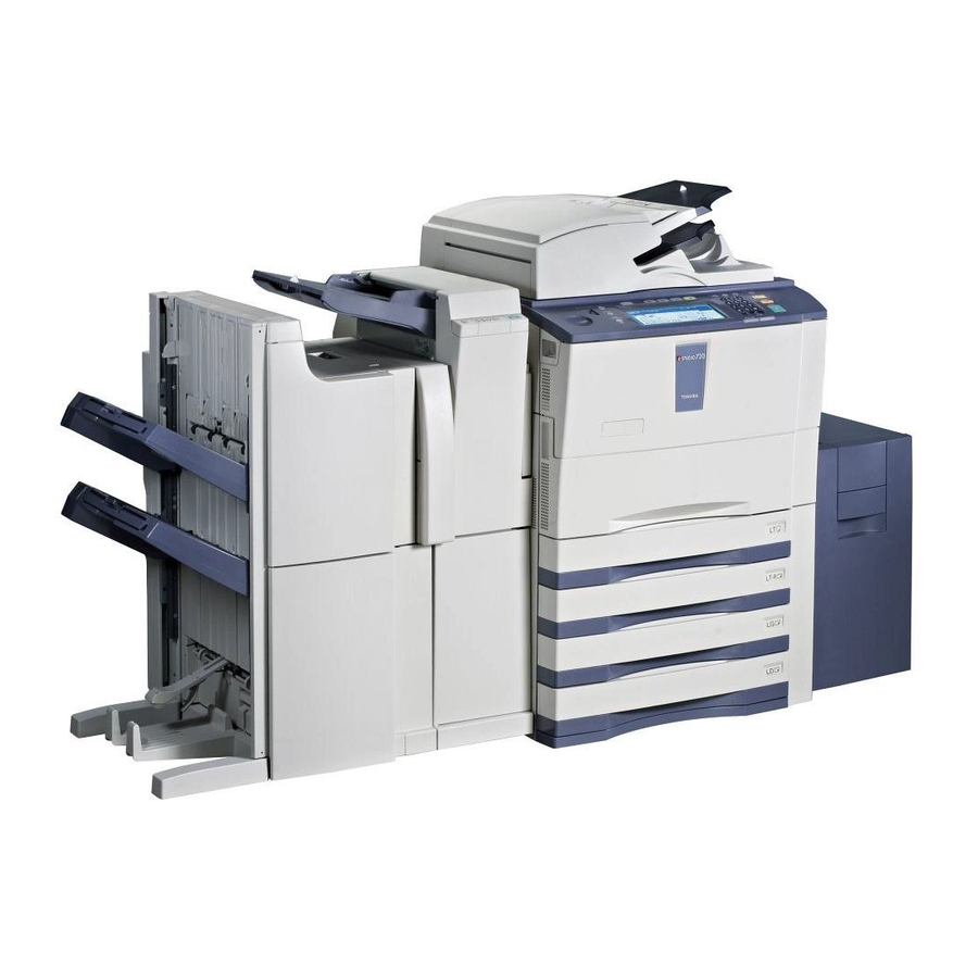
- Page 18 * The electric power is supplied to the options through the equipment. * 1.5 kW or less: TWD version of e-STUDIO520/600/720 only • Dimensions of the equipment ... See the figure below (W 698 x D 789 x H 1213 (mm))
-
Page 19: Accessories
Customer satisfaction card 1 pc. (for ASU, MJD, KRD) Approval sheet 1 pc. (for CND) Envelope 1 pc. (for CND) Packing list 1 pc. (for CND) Label 2 pc. (for MJD) March 2005 © TOSHIBA TEC e-STUDIO520/600/720/850 SPECIFICATIONS/ACCESSORIES/OPTIONS/SUPPLIES 1 - 9... -
Page 20: Options
* Up to 2 antennas (GN-3010) can be connected to the wireless LAN module (GN-1040). * When the wireless LAN module (GN-1040) and the bluetooth module (GN-2010) are installed together, only 1 antenna (GN-3010) can be connected to each. e-STUDIO520/600/720/850 SPECIFICATIONS/ACCESSORIES/OPTIONS/SUPPLIES March 2005 © TOSHIBA TEC 1 - 10... -
Page 21: Supplies
Supplies Drum OD-6510 Developer D-6000 Toner PS-ZT6000D (for other) PS-ZT6000E (for MJD) PS-ZT6000 (for NAD) Toner bag PS-TB6510E (for MJD) PS-TB6510 (for other) March 2005 © TOSHIBA TEC e-STUDIO520/600/720/850 SPECIFICATIONS/ACCESSORIES/OPTIONS/SUPPLIES 1 - 11... -
Page 22: System List
System List e-STUDIO520/600/720/850 SPECIFICATIONS/ACCESSORIES/OPTIONS/SUPPLIES March 2005 © TOSHIBA TEC 1 - 12... -
Page 23: Outline Of The Machine
OUTLINE OF THE MACHINE Sectional View Front side view NAD and SAD models. A1 A2 A7 E10 E9 E8 E7 E6 Fig.2-1 March 2005 © TOSHIBA TEC e-STUDIO520/600/720/850 OUTLINE OF THE MACHINE 2 - 1... - Page 24 TWD, ASD, ASU, AUD, MJD, CND and KRD models. A1 A2 A7 E10 E9 E8 E7 E6 Fig.2-2 e-STUDIO520/600/720/850 OUTLINE OF THE MACHINE March 2005 © TOSHIBA TEC 2 - 2...
- Page 25 Reverse/exit switching gate End fence home position sensor Reverse path roller-1 Standby side empty sensor Reverse path roller-2 Standby side mis-stacking sensor End fence stop position sensor March 2005 © TOSHIBA TEC e-STUDIO520/600/720/850 OUTLINE OF THE MACHINE 2 - 3...
- Page 26 Rear side view NAD and SAD models. Fig.2-3 e-STUDIO520/600/720/850 OUTLINE OF THE MACHINE March 2005 © TOSHIBA TEC 2 - 4...
- Page 27 TWD, ASD, ASU, AUD, MJD, CND and KRD models. Fig.2-4 March 2005 © TOSHIBA TEC e-STUDIO520/600/720/850 OUTLINE OF THE MACHINE 2 - 5...
- Page 28 2nd drawer feed clutch 3rd drawer transport clutch 3rd drawer feed clutch 4th drawer transport clutch 4th drawer feed clutch Tandem LCF tray-up motor Tandem LCF end fence motor e-STUDIO520/600/720/850 OUTLINE OF THE MACHINE March 2005 © TOSHIBA TEC 2 - 6...
-
Page 29: Electric Parts Layout
Electric Parts Layout 1) Scanner unit a. A4 series INV-EXP Fig.2-5 March 2005 © TOSHIBA TEC e-STUDIO520/600/720/850 OUTLINE OF THE MACHINE 2 - 7... - Page 30 LT series INV-EXP Fig.2-6 e-STUDIO520/600/720/850 OUTLINE OF THE MACHINE March 2005 © TOSHIBA TEC 2 - 8...
- Page 31 Heater, thermostat THMO3 Fig.2-7 March 2005 © TOSHIBA TEC e-STUDIO520/600/720/850 OUTLINE OF THE MACHINE 2 - 9...
- Page 32 2) Control panel KEY2 INV-LCD KEY1 TCP/LCD Fig.2-8 e-STUDIO520/600/720/850 OUTLINE OF THE MACHINE March 2005 © TOSHIBA TEC 2 - 10...
- Page 33 3) Laser unit a. e-STUDIO520/600/720 LDR1 Fig.2-9 March 2005 © TOSHIBA TEC e-STUDIO520/600/720/850 OUTLINE OF THE MACHINE 2 - 11...
- Page 34 LDR1 LDR2 Fig.2-10 e-STUDIO520/600/720/850 OUTLINE OF THE MACHINE March 2005 © TOSHIBA TEC 2 - 12...
- Page 35 4) Fuser related section THM3 THM2 THMO1 THM1 THMO2 IH-COIL THM4 Fig.2-11 March 2005 © TOSHIBA TEC e-STUDIO520/600/720/850 OUTLINE OF THE MACHINE 2 - 13...
- Page 36 5) Toner cartridge related section Fig.2-12 e-STUDIO520/600/720/850 OUTLINE OF THE MACHINE March 2005 © TOSHIBA TEC 2 - 14...
- Page 37 6) Toner recycle / used toner recovery unit Fig.2-13 March 2005 © TOSHIBA TEC e-STUDIO520/600/720/850 OUTLINE OF THE MACHINE 2 - 15...
- Page 38 7) Developer unit / drum / transfer belt unit related section a. Motor, sensor, switch, solenoid, lamp, thermistor SOL1 THM5 Fig.2-14 e-STUDIO520/600/720/850 OUTLINE OF THE MACHINE March 2005 © TOSHIBA TEC 2 - 16...
- Page 39 Heater, thermostat, PC board THMO4 Fig.2-15 March 2005 © TOSHIBA TEC e-STUDIO520/600/720/850 OUTLINE OF THE MACHINE 2 - 17...
- Page 40 8) Paper transport unit CLT3 CLT2 CLT1 Fig.2-16 e-STUDIO520/600/720/850 OUTLINE OF THE MACHINE March 2005 © TOSHIBA TEC 2 - 18...
- Page 41 9) Paper exit / reverse section MOT2-RV SOL2 Fig.2-17 March 2005 © TOSHIBA TEC e-STUDIO520/600/720/850 OUTLINE OF THE MACHINE 2 - 19...
- Page 42 10) Equipment (left view) SW11 Fig.2-18 e-STUDIO520/600/720/850 OUTLINE OF THE MACHINE March 2005 © TOSHIBA TEC 2 - 20...
- Page 43 11) Equipment (right view) MOT2-MT Fig.2-19 March 2005 © TOSHIBA TEC e-STUDIO520/600/720/850 OUTLINE OF THE MACHINE 2 - 21...
- Page 44 12) Bypass feed unit CLT4 SOL3 Fig.2-20 e-STUDIO520/600/720/850 OUTLINE OF THE MACHINE March 2005 © TOSHIBA TEC 2 - 22...
- Page 45 13) Paper feeding section SOL7 CLT5 CLT6 CLT7 CLT8 CLT9 CLT10 CLT11 CLT12 S44 S43 Fig.2-21 March 2005 © TOSHIBA TEC e-STUDIO520/600/720/850 OUTLINE OF THE MACHINE 2 - 23...
- Page 46 14) Tandem LCF SOL8 Fig.2-22 e-STUDIO520/600/720/850 OUTLINE OF THE MACHINE March 2005 © TOSHIBA TEC 2 - 24...
- Page 47 15) Equipment (rear view) Fig.2-23 March 2005 © TOSHIBA TEC e-STUDIO520/600/720/850 OUTLINE OF THE MACHINE 2 - 25...
- Page 48 16) AC input section a. e-STUDIO600/720: JPD model BRK1 Fig.2-24 e-STUDIO520/600/720/850 OUTLINE OF THE MACHINE March 2005 © TOSHIBA TEC 2 - 26...
- Page 49 JPD model BRK1 BRK2 Fig.2-25 March 2005 © TOSHIBA TEC e-STUDIO520/600/720/850 OUTLINE OF THE MACHINE 2 - 27...
- Page 50 NAD model, e-STUDIO600/720: NAD/SAD/TWD model, e-STUDIO850: NAD/SAD model BRK1 Fig.2-26 e-STUDIO520/600/720/850 OUTLINE OF THE MACHINE March 2005 © TOSHIBA TEC 2 - 28...
- Page 51 AUD/MJD model, e-STUDIO600/720/850: ASD/ASU/AUD/MJD/CND/KRD model, e-STUDIO850: TWD model BRK1 Fig.2-27 March 2005 © TOSHIBA TEC e-STUDIO520/600/720/850 OUTLINE OF THE MACHINE 2 - 29...
- Page 52 17) Reversing automatic document feeder a. Sensor Fig.2-28 b. Sensor Fig.2-29 e-STUDIO520/600/720/850 OUTLINE OF THE MACHINE March 2005 © TOSHIBA TEC 2 - 30...
- Page 53 Motor, sensor, switch, solenoid, PC board SOL4 SW10 SOL6 SOL5 Fig.2-30 d. Sensor Fig.2-31 March 2005 © TOSHIBA TEC e-STUDIO520/600/720/850 OUTLINE OF THE MACHINE 2 - 31...
-
Page 54: Symbols And Functions Of Various Components
SLG-FAN-MOT Cooling down the SLG board Fig.2-5 34-10 SLG board cooling fan Fig.2-6 REV-FAN-MOT1 Cooling down the reverse section Fig.2-17 15-12 Reverse section cooling (rear side) fan-1 e-STUDIO520/600/720/850 OUTLINE OF THE MACHINE March 2005 © TOSHIBA TEC 2 - 32... - Page 55 Driving the end fence in the tandem LCF Fig.2-22 9-22 Tandem LCF end fence (Only for ASD/ASU/AUD/MJD/CND/KRD motor model of all equipments and TWD model of e-STUDIO850) March 2005 © TOSHIBA TEC e-STUDIO520/600/720/850 OUTLINE OF THE MACHINE 2 - 33 05/07...
- Page 56 Detecting the opening/closing status of the Fig.2-19 29-7 Bypass feed unit cover bypass feed unit cover sensor FEED-COV-SNR Detecting the opening/closing status of the Fig.2-19 29-7 Feed cover sensor feed cover e-STUDIO520/600/720/850 OUTLINE OF THE MACHINE March 2005 © TOSHIBA TEC 2 - 34...
- Page 57 Detecting the presence of the 4th drawer Fig.2-21 7-18 4th drawer detection sen- (Only for JPD/NAD/SAD model of all equip- ments and TWD model of e-STUDIO600/ 720) March 2005 © TOSHIBA TEC e-STUDIO520/600/720/850 OUTLINE OF THE MACHINE 2 - 35...
- Page 58 Detecting the opening/closing status of the Fig.2-30 89-101 RADF opening/closing sen- RADF DF-SD-REV-SNR Detecting the transporting status of the Fig.2-31 84-31 Small original reverse sen- original at the small original reverse section e-STUDIO520/600/720/850 OUTLINE OF THE MACHINE March 2005 © TOSHIBA TEC 2 - 36...
- Page 59 (voltage-generating cir- cuit interlocked with these covers) accord- ing to the opening/closing status of the front cover (lower) or left lower cover (Cover open: Shut off) March 2005 © TOSHIBA TEC e-STUDIO520/600/720/850 OUTLINE OF THE MACHINE 2 - 37...
- Page 60 Driving the separation roller, feed roller and Fig.2-21 7-26 4th drawer feed clutch pickup roller of the 4th drawer (Only for JPD/NAD/SAD model of all equip- ments and TWD model of e-STUDIO600/ 720) e-STUDIO520/600/720/850 OUTLINE OF THE MACHINE March 2005 © TOSHIBA TEC 2 - 38...
- Page 61 Fig.2-10 32-1B (SNS board) PWA-F-FUS Relaying power to the drum damp heater Fig.2-15 21-30 Fuse PC board (Optional for NAD/MJD model, standard for (FUS board) other models) March 2005 © TOSHIBA TEC e-STUDIO520/600/720/850 OUTLINE OF THE MACHINE 2 - 39...
- Page 62 Detecting the surface temperature of the Fig.2-11 27-28 Pressure roller thermistor pressure roller THM5 THMS-DRM Detecting the ambient temperature of the Fig.2-14 50-12 Drum thermistor drum surface e-STUDIO520/600/720/850 OUTLINE OF THE MACHINE March 2005 © TOSHIBA TEC 2 - 40...
- Page 63 Fig.2-25 52-3B Breaker-2 (Only for JPD model of e-STUDIO850) RELEY Controlling AC power supplied to the fuser Fig.2-25 52-110 Relay unit (Only for JPD model of e-STUDIO850) March 2005 © TOSHIBA TEC e-STUDIO520/600/720/850 OUTLINE OF THE MACHINE 2 - 41...
-
Page 64: System Block Diagram
System Block Diagram Fig.2-32 e-STUDIO520/600/720/850 OUTLINE OF THE MACHINE March 2005 © TOSHIBA TEC 2 - 42... -
Page 65: Installation And Replacement Of Covers
Front right inner cover Take off the front cover Front right inner cover P.2-43 "[A] Front cover (Upper/Lower)"). Remove 2 screws to take off the front right inner cover. Fig.2-35 March 2005 © TOSHIBA TEC e-STUDIO520/600/720/850 OUTLINE OF THE MACHINE 2 - 43... - Page 66 P.2-44 "[C] Top right cover"). Take off the top left cover P.2-44 "[D] Top left cover"). Remove 2 screws to take off the top rear cover. Fig.2-38 e-STUDIO520/600/720/850 OUTLINE OF THE MACHINE March 2005 © TOSHIBA TEC 2 - 44...
- Page 67 Remove 8 screws to take off the right center Right center cover cover. Fig.2-40 [H] Right rear cover Remove 2 screws and take off the right rear cover. Right rear cover Fig.2-41 March 2005 © TOSHIBA TEC e-STUDIO520/600/720/850 OUTLINE OF THE MACHINE 2 - 45...
- Page 68 Remove 6 screws to take off the left lower cover. Left lower cover ( Exit cover ) Fig.2-43 Left rear cover Remove 1 screw to take off the left rear cover. Left rear cover Fig.2-44 e-STUDIO520/600/720/850 OUTLINE OF THE MACHINE March 2005 © TOSHIBA TEC 2 - 46...
- Page 69 Rear cover Loosen 1 screw fixing the ozone filter. Remove 7 screws. Then release 2 hooks to Rear cover take off the rear cover. Fig.2-45 March 2005 © TOSHIBA TEC e-STUDIO520/600/720/850 OUTLINE OF THE MACHINE 2 - 47...
-
Page 70: Installation And Separation Of Pc Boards
Remove 5 screws to take off the leaf spring. Leaf spring Fig.2-47 Disconnect 7 connectors of the SYS board. Remove 6 screws to take off the SYS board. SYS board Fig.2-48 e-STUDIO520/600/720/850 OUTLINE OF THE MACHINE March 2005 © TOSHIBA TEC 2 - 48... - Page 71 Fig.2-50 Disconnect 20 connectors of the LGC board. Remove 6 screws to take off the LGC board. LGC board Fig.2-51 March 2005 © TOSHIBA TEC e-STUDIO520/600/720/850 OUTLINE OF THE MACHINE 2 - 49...
- Page 72 P.2-49 "[B] Logic PC board (LGC board)" Disconnect 20 connectors of the LGC board. Remove 6 screws and take off the LGC board case with the board. Fig.2-54 e-STUDIO520/600/720/850 OUTLINE OF THE MACHINE March 2005 © TOSHIBA TEC 2 - 50...
- Page 73 Release the hook to take off the switching regulator. Switching regurator Note: When installing or taking off the switching regulator and its cover, be sure that their har- nesses are not caught. Fig.2-57 March 2005 © TOSHIBA TEC e-STUDIO520/600/720/850 OUTLINE OF THE MACHINE 2 - 51...
-
Page 74: Removal And Installation Of Options
Large Capacity Feeder (LCF) Shut down the equipment and unplug the power cable. Press the button to separate the Large Capacity Feeder (LCF) from the equipment. Fig.2-60 e-STUDIO520/600/720/850 OUTLINE OF THE MACHINE March 2005 © TOSHIBA TEC 2 - 52... - Page 75 Connector cover Screw Fig.2-61 Disconnect the interface cable of the Large Capacity Feeder (LCF). Interface cable Fig.2-62 Remove 2 fixing screws on the rear side. Screw Fig.2-63 March 2005 © TOSHIBA TEC e-STUDIO520/600/720/850 OUTLINE OF THE MACHINE 2 - 53...
- Page 76 Lift the Large Capacity Feeder (LCF) and take it off from the slide rail. Note: Be careful when lifting the Large Capacity Feeder (LCF) because it is heavy. Fig.2-65 e-STUDIO520/600/720/850 OUTLINE OF THE MACHINE March 2005 © TOSHIBA TEC 2 - 54...
-
Page 77: Copy Process
(5) Development: (10)Discharging: Makes the negatively-charged toner Discharges any remaining negative charge adhere to the photoconductive drum and on the drum. forms a visible image. March 2005 © TOSHIBA TEC e-STUDIO520/600/720/850 COPY PROCESS 3 - 1... -
Page 78: Details Of Copy Process
As this image on the drum formed by the negative potential is invisible, it is called an “electrostatic latent image’’. Time ( t ) Black area of original -300 White area of original -600 Discharge Charging process process Electric potential on the photoconductive drum Fig.3-3 e-STUDIO520/600/720/850 COPY PROCESS March 2005 © TOSHIBA TEC 3 - 2... - Page 79 Image processing section Fig.3-5 (Example) CCD light Value of image receiving signals to be amount output Light Difference between "light " and "dark" is divided into 256 steps. Dark Fig.3-6 March 2005 © TOSHIBA TEC e-STUDIO520/600/720/850 COPY PROCESS 3 - 3...
- Page 80 Magnetic roller Toner Carrier ( always attracted onto the magnet ) Toner Fig.3-8 Bias voltage -394V (-200 to -800V) DC+AC Toner Photoconductive drum Photoconductive layer Aluminum conductive base Fig.3-9 e-STUDIO520/600/720/850 COPY PROCESS March 2005 © TOSHIBA TEC 3 - 4...
- Page 81 Carrier: Consists of ferrite and resin coating on its surface to provide consistent frictional electrification. Carbon ( 5-10% ) 5-20 µm Ferrite Resin ( 90-95% ) [ Toner ] 30-100 µm [ Carrier ] Fig.3-11 March 2005 © TOSHIBA TEC e-STUDIO520/600/720/850 COPY PROCESS 3 - 5...
- Page 82 5) Copy density and image quality mode As indicated in the figure below, the life of the toner cartridge varies depending on the copy mode and coverage of originals e-STUDIO520/600/720/850 COPY PROCESS March 2005 © TOSHIBA TEC 3 - 6...
- Page 83 Then it flows to the paper and photo conductor. The toner, which has been developed on the photo conductor, is transferred to this paper with an electric charge. Drum Transfer belt Paper Fig.3-15 March 2005 © TOSHIBA TEC e-STUDIO520/600/720/850 COPY PROCESS 3 - 7...
- Page 84 Paper movement copy paper which fails to be separated. Transfer belt Fig.3-17 e-STUDIO520/600/720/850 COPY PROCESS March 2005 © TOSHIBA TEC 3 - 8...
- Page 85 Also, too prevent the cleaning blade from scratching the surface of the drum to make a circumfer- ential streak, the varistor is attached between the brush and earth. 2) Cleaning blade scrapes off the residual toner on the drum. March 2005 © TOSHIBA TEC e-STUDIO520/600/720/850 COPY PROCESS 3 - 9...
- Page 86 The photoconductive drum becomes electrically conductive. All the (-) charges remaining on the photoconductive drum are conducted to the ground. The preparation for the next copy is completed. Discharge LED array Drum Fig.3-21 e-STUDIO520/600/720/850 COPY PROCESS March 2005 © TOSHIBA TEC 3 - 10...
-
Page 87: Comparison Of Copy Process To E-Studio550/650/810
Cleaning web (for fuser roller cleaning) Pressure roller cleaning felt roller none Pressure roller cleaning metal roller none • Heater IH coil (Induction heating system) ON/OFF control by thermistor March 2005 © TOSHIBA TEC e-STUDIO520/600/720/850 COPY PROCESS 3 - 11... - Page 88 COPY PROCESS March 2005 © TOSHIBA TEC 3 - 12...
-
Page 89: General Operation
GENERAL OPERATION Overview of Operation Copier operation Operation during warming-up, pre-running and standby Automatic feed copying by pressing [START] button Copying operation Bypass copying Interrupt copying March 2005 © TOSHIBA TEC e-STUDIO520/600/720/850 GENERAL OPERATION 4 - 1... -
Page 90: Description Of Operation
Each drawer tray goes up o Initialization of the writing system The polygonal motor (M2) rotates at a high speed. (e-STUDIO850) The polygonal motor (M2) rotates at a low speed. (e-STUDIO520/600/720) The beam position is controlled. (e-STUDIO850) o Other The main charger cleaner operates. -
Page 91: Drawer Feed Copying With The [Start] Button
The scan motor (M1) is turned OFF. o The exposure lamp (EXP) is turned OFF. o The registration motor (M16) is turned OFF (after the trailing edge of the paper passes the regis- tration roller). March 2005 © TOSHIBA TEC e-STUDIO520/600/720/850 GENERAL OPERATION 4 - 3... - Page 92 The rotation speed of the polygonal motor (M2) switches from a high speed to a low speed. (e-STUDIO520/600/720) o "READY" appears and the equipment enters the ready state. e-STUDIO520/600/720/850 GENERAL OPERATION March 2005 © TOSHIBA TEC 4 - 4...
- Page 93 Timing chart for copying one A4 sized sheet fed from the 1st drawer [e-STUDIO520/600/720] Fig.4-1 March 2005 © TOSHIBA TEC e-STUDIO520/600/720/850 GENERAL OPERATION 4 - 5...
- Page 94 [e-STUDIO850] Fig.4-2 e-STUDIO520/600/720/850 GENERAL OPERATION March 2005 © TOSHIBA TEC 4 - 6...
-
Page 95: Bypass Feed Copying
When the LED "INTERRUPT" is turned OFF by pressing the [INTERRUPT] button, the equip- ment returns to the status before the interruption. o "Ready to resume job 1" appears. 4) Pressing the [START] button o The copying operation before the interruption resumes. March 2005 © TOSHIBA TEC e-STUDIO520/600/720/850 GENERAL OPERATION 4 - 7... -
Page 96: Detection Of Abnormality
[When the drawer is installed] The drawer is detected. Tray goes up (the drawer empty sensor (S31, 37, 43, 49) is turned OFF). "Add paper" appears. The [START] button is disabled. e-STUDIO520/600/720/850 GENERAL OPERATION March 2005 © TOSHIBA TEC 4 - 8... - Page 97 Pick-up failure in bypass The clear paper symbol is displayed: E120 Copying operation is disabled. Solution: Remove the paper from the bypass tray. o The bypass paper sensor (S27) is turned OFF. March 2005 © TOSHIBA TEC e-STUDIO520/600/720/850 GENERAL OPERATION 4 - 9...
- Page 98 When a sheet of reversed paper is transported, horizontal transport sensor-1, -2 (S19, 20) or reverse sensor-1 (S23) does not detect paper within a fixed period of time. Paper jam (E511, E512, E540) e-STUDIO520/600/720/850 GENERAL OPERATION March 2005 © TOSHIBA TEC 4 - 10...
- Page 99 Check the error code displayed on the control panel when "Call for service" appears, and handle the abnormality in reference to the error code table in the Service Handbook. March 2005 © TOSHIBA TEC e-STUDIO520/600/720/850 GENERAL OPERATION 4 - 11...
-
Page 100: Flowchart
IH coil ON (Start initializing) Scan motor ON Tray-up motor ON Is registration sensor ON? intermediate transport sensor Is exit sensor ON? horizontal transport sensor Is reverse sensor ON? Fig.4-3 e-STUDIO520/600/720/850 GENERAL OPERATION March 2005 © TOSHIBA TEC 4 - 12... - Page 101 Is fuser roller temperature high enough to Call for service Call for service Call for service be ready? "C410" "C440" "CA10" Pre-running finished READY Fig.4-4 March 2005 © TOSHIBA TEC e-STUDIO520/600/720/850 GENERAL OPERATION 4 - 13...
-
Page 102: Automatic Feed Copying
"CA20" Carriage stopped Is remaining set number 0? Scanning system control finished Is fuser unit Paper jam transport sensor ON? Laser OFF "E010" Process system control finished Fig.4-5 e-STUDIO520/600/720/850 GENERAL OPERATION March 2005 © TOSHIBA TEC 4 - 14... - Page 103 Developer bias OFF Drum motor OFF Transfer belt motor OFF Fuser motor OFF Developer unit motor OFF Recycle toner transport motor OFF Used toner transport motor OFF Drum reversed Standby Fig.4-6 March 2005 © TOSHIBA TEC e-STUDIO520/600/720/850 GENERAL OPERATION 4 - 15...
- Page 104 GENERAL OPERATION March 2005 © TOSHIBA TEC 4 - 16...
-
Page 105: Control Panel
If a paper jam or service call has occurred, its error code is displayed on the LCD panel so that the user can recognize which error has occurred. Fig.5-1 March 2005 © TOSHIBA TEC e-STUDIO520/600/720/850 CONTROL PANEL 5 - 1... -
Page 106: Items Shown On The Control Panel
Displays buttons and messages. Fig.5-2 2) Paper jam display Displays error codes, paper jam position and paper jam release guidance. Error code Paper jam position Paper jam release guidance Fig.5-3 e-STUDIO520/600/720/850 CONTROL PANEL March 2005 © TOSHIBA TEC 5 - 2... - Page 107 3) Service call display Displays error codes and service call symbols. Error code Service call symbol Fig.5-4 March 2005 © TOSHIBA TEC e-STUDIO520/600/720/850 CONTROL PANEL 5 - 3...
-
Page 108: Display
Scanning is enabled READY Stapling jam occurred in finisher (CHECK STAPLER) READY (ADD PAPER) No paper in drawer Cleared by supplying papers Press JOB STATUS button • Scanning is enabled e-STUDIO520/600/720/850 CONTROL PANEL March 2005 © TOSHIBA TEC 5 - 4... - Page 109 Cover Sheet Copying Mode/Sheet Inser- tion Mode Copy size: A4/LT only Displayed when the paper size which is not specified for “Book-type duplex copying” or “Dual-page” is set March 2005 © TOSHIBA TEC e-STUDIO520/600/720/850 CONTROL PANEL 5 - 5...
- Page 110 Trouble in the stapler unit in finisher Check staple cartridge No stapler in finisher section Job interrupted job 1 saved Interrupt copying is accepted Ready to resume job 1 Interrupt copying is cancelled (fin- ished) e-STUDIO520/600/720/850 CONTROL PANEL March 2005 © TOSHIBA TEC 5 - 6...
- Page 111 Time for periodic mainte- PM cycle Maintenance and inspection are per- nance • Displayed at the time for mainte- formed by qualified service techni- nance cian • Copying is available March 2005 © TOSHIBA TEC e-STUDIO520/600/720/850 CONTROL PANEL 5 - 7...
- Page 112 (Messages 82 and 83 Displayed when the surface poten- Refer to chapter 5.1.15 and 5.1.16. above appear alternately.) tial control error and the image qual- /Service Handbook. ity control error occur e-STUDIO520/600/720/850 CONTROL PANEL March 2005 © TOSHIBA TEC 5 - 8 05/04...
-
Page 113: Relation Between The Equipment State And Operator's Operation
Displays USER Display not changed Display not changed Display not changed FUNCTIONS] button FUNCTIONS screen Press [HELP] button Displays HELP Displays HELP Display not changed Display not changed screen screen March 2005 © TOSHIBA TEC e-STUDIO520/600/720/850 CONTROL PANEL 5 - 9... - Page 114 Press [START] Displays “Wait Warming Up Display not changed Display not changed button with the “COPYING” Auto Start” is original set on RADF displayed e-STUDIO520/600/720/850 CONTROL PANEL March 2005 © TOSHIBA TEC 5 - 10...
- Page 115 PLATE] button PLATE screen changed changed PLATE screen changed Press [USER Displays USER Display not Display not Displays USER Display not FUNCTIONS] FUNCTIONS changed changed FUNCTIONS changed button screen screen March 2005 © TOSHIBA TEC e-STUDIO520/600/720/850 CONTROL PANEL 5 - 11...
- Page 116 “COPYING” and changed “COPYING” and “COPYING” and mode is cleared original set on RADF starts RADF starts RADF starts and displays RADF feeding feeding feeding BASIC screen e-STUDIO520/600/720/850 CONTROL PANEL March 2005 © TOSHIBA TEC 5 - 12...
-
Page 117: Operation
The LCD panel is an STN blue mode transmissive type LCD with a 640 x 240-dot display capacity. It consists of a driver LSI, frame, printed circuit board, and lateral type CFL backlight. * STN: Super Twisted Nematic March 2005 © TOSHIBA TEC e-STUDIO520/600/720/850 CONTROL PANEL 5 - 13... -
Page 118: Lcd Panel
D102 (240, 1) (240, 2) ·········································· (240, 640) Com2 VDD, 160 Out 160 Out Seg1 Seg4 E102 E101 E102 E101 VDD, V0, V2, V3, VSS LOAD DISP D3-D0 Fig.5-6 e-STUDIO520/600/720/850 CONTROL PANEL March 2005 © TOSHIBA TEC 5 - 14... - Page 119 (d) The LCD controller/driver reads the display data from the RAM, and outputs the data to the LCD panel. SYS board ASIC System CPU Flash ROM controller Control panel LCD panel Key switches touch panel Control panel Fig.5-7 March 2005 © TOSHIBA TEC e-STUDIO520/600/720/850 CONTROL PANEL 5 - 15...
-
Page 120: Led Display Circuit
1) The transistor (Q1) connected to the LED anode is ON. 2) The transistor (Q7) connected to the LED cathode side is ON. The LED is turned ON when 1) and 2) are satisfied. e-STUDIO520/600/720/850 CONTROL PANEL March 2005 © TOSHIBA TEC 5 - 16... -
Page 121: Disassembly And Replacement
Remove 2 screws and take off the toner car- tridge catcher. Toner cartridge catcher Fig.5-10 Remove 2 screws and take off the control panel lower cover. Control panel lower cover Fig.5-11 Disconnect 2 connectors. Fig.5-12 March 2005 © TOSHIBA TEC e-STUDIO520/600/720/850 CONTROL PANEL 5 - 17... - Page 122 Take off the control panel unit P.5-17 "[A] Control panel unit"). Take off the DSP board P.5-18 "[B] Display PC board (DSP)"). Remove 8 screws and take off the base stay. Base stay Fig.5-15 e-STUDIO520/600/720/850 CONTROL PANEL March 2005 © TOSHIBA TEC 5 - 18...
- Page 123 Remove 8 screws to take off the base stay. Disconnect 3 connectors. Remove 4 screws to remove the Mylar. Mylar Fig.5-17 Remove 18 screws and take off the KEY1 board. KEY1 board Fig.5-18 March 2005 © TOSHIBA TEC e-STUDIO520/600/720/850 CONTROL PANEL 5 - 19...
- Page 124 2. Be sure that no dust or stain is on the LCD panel or the touch panel before the installation. Touch panel Fig.5-21 e-STUDIO520/600/720/850 CONTROL PANEL March 2005 © TOSHIBA TEC 5 - 20...
-
Page 125: Scanning Section
Drive pulley Exposure lamp Carriage-1 Rail for carriage-1 Original glass Reflector Shading correction plate CCD board Lens SLG board Carriage-2 CCD sensor Rail for carriage-2 Fig.6-1 March 2005 © TOSHIBA TEC e-STUDIO520/600/720/850 SCANNING SECTION 6 - 1... -
Page 126: Construction
The size of the original placed on the glass is instantly detected using the automatic original detec- tion sensors (S1-5) fixed on the base frame without moving the carriage-1. e-STUDIO520/600/720/850 SCANNING SECTION March 2005 © TOSHIBA TEC 6 - 2... - Page 127 SLG board (SLG). 7) SLG board (SLG) This is a board to perform the image correction, such as the signal synthesis, signal amplification, A/ D conversion and shading correction. March 2005 © TOSHIBA TEC e-STUDIO520/600/720/850 SCANNING SECTION 6 - 3...
-
Page 128: Operation
The scan motor (M1) with the unipolar fixed current chopper method is driven by the stepping motor driver STK672-410 (IC19). SLG board +36V Scan motor MOTREF-0 MOTEN-0 MOTRST-0 MOTDIR-0 Motor Scanner CPU driver MOTCLK-1 MOTMD1-0 MOTMD2-0 MOTMD3-0 IC19 IC10 Fig.6-4 e-STUDIO520/600/720/850 SCANNING SECTION March 2005 © TOSHIBA TEC 6 - 4... - Page 129 OFF. Reset MOTRST-0 Input Reset for the whole system. Internal circuit of the driver is initialized by setting the motor to "L" level (pulse interval: 10µsec. or more). March 2005 © TOSHIBA TEC e-STUDIO520/600/720/850 SCANNING SECTION 6 - 5...
-
Page 130: Control For Exposure Lamp
Original Shading correction plate Exposure lamp (Xenon lamp) Lighting device for xenon lamp (Lamp inverter board) CCD board CCD sensor SLG board Analog Front End Scanner ASIC (AFE) Fig.6-5 e-STUDIO520/600/720/850 SCANNING SECTION March 2005 © TOSHIBA TEC 6 - 6... -
Page 131: Exposure Lamp
This ultraviolet rays convert the fluorescer into visible light. (1) Electrode (2) Electron (3) Xenon atom (4) Ultraviolet lay (5) Fluorescer (6) Visible light (irradiated from the opening to outside the pipe) (7) Openig (8) Harness Fig.6-7 March 2005 © TOSHIBA TEC e-STUDIO520/600/720/850 SCANNING SECTION 6 - 7... -
Page 132: Control Circuit For Exposure Lamp
(Lamp inverter board) 5VSWON-0 Q102 Fig.6-8 Working conditions LMPON-0 State of WDTOUT-0 5VSWON-0 +5VSW Q102 Xenon lamp (Lamp drive signal) equipment Normal operation Scanner CPU overdriving Call for Service e-STUDIO520/600/720/850 SCANNING SECTION March 2005 © TOSHIBA TEC 6 - 8... -
Page 133: Ccd Control
( S - K ) I = k ( W - K ) Coefficient Image data before correction Black data (stored in "Black" memory) White data (stored in "White" memory) March 2005 © TOSHIBA TEC e-STUDIO520/600/720/850 SCANNING SECTION 6 - 9... -
Page 134: Automatic Original Size Detection Circuit
[ A4 Series ] [ LT Series ] Original Original glass Original Original glass APS-R APS-R APS-C APS-C APS-3 APS-3 APS-2 APS-1 APS-2 Fig.6-10 e-STUDIO520/600/720/850 SCANNING SECTION March 2005 © TOSHIBA TEC 6 - 10... -
Page 135: Process Of Original Size Detection
[ LT Series ] +5.1VD +5.1VD APS-R APS-R APS-C IC10 APS-C IC10 Reflection type Reflection type APS-3 photosensor photosensor Scanner Scanner APS-3 APS-2 APS-1 APS-2 SLG board SLG board Fig.6-11 March 2005 © TOSHIBA TEC e-STUDIO520/600/720/850 SCANNING SECTION 6 - 11... - Page 136 Sensor detection points [A4 Series] APS-R APS-C A5-R B5-R A4-R APS-3 APS-1 APS-2 Fig.6-12 [LT Series] APS-R APS-C ST-R APS-3 LT-R APS-2 Fig.6-13 e-STUDIO520/600/720/850 SCANNING SECTION March 2005 © TOSHIBA TEC 6 - 12...
- Page 137 Retains the latest original size (or no original state) recognized right before the APS operation sen- sor is turned ON regardless of the state of the APS sensor output signals. March 2005 © TOSHIBA TEC e-STUDIO520/600/720/850 SCANNING SECTION 6 - 13...
- Page 138 The light emitting diode is driven by a pulse having a 130-µsec cycle and an 8-µsec ON time. When the phototransistor receives the same signal as this pulse, it is determined that there is an original. The pulse modulation is performed inside the reflection type phototransistor. e-STUDIO520/600/720/850 SCANNING SECTION March 2005 © TOSHIBA TEC 6 - 14...
-
Page 139: Disassembly And Replacement
Remove 3 screws to take off the original glass holder. Original glass holder Fig.6-15 Remove 2 caps and 2 screws to take off the original glass. Original glass Fig.6-16 March 2005 © TOSHIBA TEC e-STUDIO520/600/720/850 SCANNING SECTION 6 - 15... - Page 140 [C] Automatic original detection sensor (APS sensor) (S1 / S2 / S3 / S4 / S5) Take off the lens cover P.6-16 "[B] Lens cover"). Remove 2 screws to take off the remaining APS sensor with its bracket. Fig.6-19 e-STUDIO520/600/720/850 SCANNING SECTION March 2005 © TOSHIBA TEC 6 - 16...
- Page 141 LT series (S2 / S3 / S4) Take off the lens cover LT series P.6-16 "[B] Lens cover"). Take off 3 APS sensors by disconnecting 1 connector and removing 1 screw for each sensor. Fig.6-22 March 2005 © TOSHIBA TEC e-STUDIO520/600/720/850 SCANNING SECTION 6 - 17...
- Page 142 Take off the original glass P.6-15 "[A] Original glass"). Move the carriage-1 to the left side. Carriage-1 Fig.6-24 Disconnect the connector, release the clamp and remove 1 screw of the exposure lamp. Fig.6-25 e-STUDIO520/600/720/850 SCANNING SECTION March 2005 © TOSHIBA TEC 6 - 18...
- Page 143 Scanning section control PC board (SLG) Take off the lens cover P.6-16 "[B] Lens cover"). Disconnect 8 connectors and remove 4 screws to take off the SLG board. SLG board Fig.6-28 March 2005 © TOSHIBA TEC e-STUDIO520/600/720/850 SCANNING SECTION 6 - 19...
- Page 144 1. When replacing the lens unit, do not touch 10 screws denoted with arrows in the figure. Fig.6-30 2. Handle the unit with extra care. Do not touch the adjusted area or lens. Fig.6-31 e-STUDIO520/600/720/850 SCANNING SECTION March 2005 © TOSHIBA TEC 6 - 20...
- Page 145 Carriage-1 Bracket Fig.6-33 Disconnect 1 connector of the SLG board. Sticker Then remove 3 stickers and release the har- ness from 2 clamps. Clamp Fig.6-34 March 2005 © TOSHIBA TEC e-STUDIO520/600/720/850 SCANNING SECTION 6 - 21...
- Page 146 Fig.6-36 Carriage-2 Take off the carriage-1 P.6-21 "[H] Carriage-1"). Install the wire holder jig on the wire pulley to prevent the wire from being loosened. Wire holder jig Fig.6-37 e-STUDIO520/600/720/850 SCANNING SECTION March 2005 © TOSHIBA TEC 6 - 22...
- Page 147 Lamp inverter board (INV-EXP) Take off the carriage-1 P.6-21 "[H] Carriage-1"). Lamp inverter board Disconnect 2 connectors and remove 2 screws to take off the lamp inverter board. Carriage-1 Fig.6-40 March 2005 © TOSHIBA TEC e-STUDIO520/600/720/850 SCANNING SECTION 6 - 23...
- Page 148 3) Loosen the 2 screws, which fix the motor bracket, and then tighten them when the belt is strained. 4) Remove the belt tension jig and install the DF bracket. Screw Fig.6-43 e-STUDIO520/600/720/850 SCANNING SECTION March 2005 © TOSHIBA TEC 6 - 24...
- Page 149 Disconnect 1 connector to take off the car- riage home position sensor. Note: When the sensor has been replaced, be sure to put a new protection sheet. Carriage home position sensor Fig.6-44 March 2005 © TOSHIBA TEC e-STUDIO520/600/720/850 SCANNING SECTION 6 - 25...
- Page 150 SCANNING SECTION March 2005 © TOSHIBA TEC 6 - 26...
-
Page 151: Image Processing
Laser control PC board Smoothing processing, external input system interface, image area control, laser (PLG) related control and printer high quality image processing March 2005 © TOSHIBA TEC e-STUDIO520/600/720/850 IMAGE PROCESSING 7 - 1 05/07... - Page 152 Images are processed by the SLG board (SLG) and PLG board (PLG) in this equipment. The image signal read in the scanning function is processed in SLG board (SLG) and the printer image signal is processed in the PLG board (PLG). e-STUDIO520/600/720/850 IMAGE PROCESSING March 2005 © TOSHIBA TEC 7 - 2...
-
Page 153: Configuration
Smoothing processing External input system interface Image area control Laser related control Printer high-quality image processing LDR board ( LDR ) Image data flow Laser drive Fig.7-3 March 2005 © TOSHIBA TEC e-STUDIO520/600/720/850 IMAGE PROCESSING 7 - 3 05/07... -
Page 154: Scanning Section Control Pc Board (Slg)
<Example> Dynamic range Extended dynamic range After range width width adjustment Back- ground Text Lower Density Higher Lower Density Higher Histogram Fig.7-4 e-STUDIO520/600/720/850 IMAGE PROCESSING March 2005 © TOSHIBA TEC 7 - 4... - Page 155 Solid black area Low contrast area Original Image signal After correction Fig.7-6 March 2005 © TOSHIBA TEC e-STUDIO520/600/720/850 IMAGE PROCESSING 7 - 5...
- Page 156 6) External output system interface This function controls the output of the output interface. e-STUDIO520/600/720/850 IMAGE PROCESSING March 2005 © TOSHIBA TEC 7 - 6...
- Page 157 7) Scanner high quality image processing This function corrects the image signals scanned by the scanner and reproduces them in a higher image quality. March 2005 © TOSHIBA TEC e-STUDIO520/600/720/850 IMAGE PROCESSING 7 - 7...
-
Page 158: Laser Control Pc Board (Plg)
4) Laser related control This function performs the APC (Auto Power Control). 5) Printer high quality processing This function reproduces the image signals output from the printer controller sharper. e-STUDIO520/600/720/850 IMAGE PROCESSING March 2005 © TOSHIBA TEC 7 - 8... -
Page 159: Laser Driving Pc Board (Ldr)
Image signals processed on the PLG board (PLG) are then processed by ASIC for writing control and LDR board (LDR). The signal is then laser controlled and written on the drum. P.8-7 "8.2.5 Laser driving board (LDR1/LDR2 board)") March 2005 © TOSHIBA TEC e-STUDIO520/600/720/850 IMAGE PROCESSING 7 - 9... - Page 160 IMAGE PROCESSING March 2005 © TOSHIBA TEC 7 - 10...
-
Page 161: Laser Optical Unit
This unit must not be disassembled in the field because it is finely adjusted and very sensitive to dust. The laser unit with 2 beams is used only for the e-STUDIO850, and the 1-beam type for the e- STUDIO520/600/720. Fig.8-1 March 2005 © TOSHIBA TEC e-STUDIO520/600/720/850 LASER OPTICAL UNIT 8 - 1... - Page 162 Laser control PC board Polygonal motor H-sync detection PC board 2nd turnup mirror H-sync turnup mirror 1st turnup mirror Slit glass [ Laser optical unit overview ] Fig.8-2 e-STUDIO520/600/720/850 LASER OPTICAL UNIT March 2005 © TOSHIBA TEC 8 - 2...
- Page 163 Polygonal motor 2nd turnup mirror Laser control PC board H-sync turnup mirror 1st turnup mirror Slit glass ( Laser beam exit ) [ Laser optical unit overview ] Fig.8-3 March 2005 © TOSHIBA TEC e-STUDIO520/600/720/850 LASER OPTICAL UNIT 8 - 3...
-
Page 164: Structure
"CAUTION. HOT", "CAUTION. HIGH VOLTAGE", "CAUTION. LASER BEAM", etc. to see if there is any dirt on their surface and if they are properly stuck to the equipment. e-STUDIO520/600/720/850 LASER OPTICAL UNIT March 2005 © TOSHIBA TEC 8 - 4... -
Page 165: Polygonal Motor Unit
Approx. 35746.946 rpm (FAX 16.0 x 15.4 dot/mm) b. Polygonal mirror The e-STUDIO520/600/720 has a 1-beam type of laser unit. One laser beam emitted from the laser diode is reflected by this mirror. As the polygonal mirror is rotated by the polygonal motor (M2), the reflected laser beam moves in sync with the rotation. - Page 166 Polygonal mirror cover The polygonal mirror cover reduces wind damage and noise, prevents adhesion of foreign matter on the mirror surface and releases heat by sealing the polygonal mirror. e-STUDIO520/600/720/850 LASER OPTICAL UNIT March 2005 © TOSHIBA TEC 8 - 6...
-
Page 167: Ft Lenses 1 And 2
Laser driving board (LDR1/LDR2 board) This control board has the following functions: a. APC control function (adjusts disparity of the laser intensity caused by temperature) b. Laser ON/OFF function March 2005 © TOSHIBA TEC e-STUDIO520/600/720/850 LASER OPTICAL UNIT 8 - 7... -
Page 168: Slit Glass
8.2.6 Slit glass Slit glass is located where the laser beams are output from the laser optical unit, and it protects the unit from dust. e-STUDIO520/600/720/850 LASER OPTICAL UNIT March 2005 © TOSHIBA TEC 8 - 8... -
Page 169: Laser Diode Control Circuit
The initial beam emission is adjusted to be approx. 2.5 mW (510 µW on the drum surface) in the e-STUDIO520/600/720, and approx. 3.0 mW (300 µW on the drum surface) in the e-STUDIO850. The voltage of the monitor output, which has been regulated by this adjustment, is then fed back to a laser power comparison circuit. -
Page 170: Polygonal Motor Control Circuit
Low level High level PMON-0 Polygonal motor ON signal PMCLK-1 Polygonal motor reference clock PMOK-0 Polygonal motor PLL control signal Rotating at a constant Stopping or error speed e-STUDIO520/600/720/850 LASER OPTICAL UNIT March 2005 © TOSHIBA TEC 8 - 10... -
Page 171: Laser Unit Cooling Fan Control Circuit
Relation between each signal level and the rotation of the fan (L = Low level, H = High level) LDFOF-1 LDFAN-0 Rotation of Fan High speed Low speed Stopping March 2005 © TOSHIBA TEC e-STUDIO520/600/720/850 LASER OPTICAL UNIT 8 - 11... -
Page 172: Disassembly And Replacement
Remove 2 screws and take off the laser unit fixing stay. Fig.8-13 Disconnect 1 connector and remove 2 screws to take off the laser unit cooling fan. Laser unit cooling fan Fig.8-14 e-STUDIO520/600/720/850 LASER OPTICAL UNIT March 2005 © TOSHIBA TEC 8 - 12... - Page 173 Remove the original glass. P.6-15 "[A] Original glass") Loosen 2 laser unit setscrews. Fig.8-16 Disconnect 2 connectors and pull out the laser unit. Laser optical unit Fig.8-17 March 2005 © TOSHIBA TEC e-STUDIO520/600/720/850 LASER OPTICAL UNIT 8 - 13 05/04...
- Page 174 4. Do not disassemble the laser optical unit in the field because it is precisely adjusted and very sensitive to dust and Slit glass stain. Fig.8-20 e-STUDIO520/600/720/850 LASER OPTICAL UNIT March 2005 © TOSHIBA TEC 8 - 14 05/04...
-
Page 175: Paper Feeding System
Moreover, the composition of the paper feeding unit differs depending on the destination (machine version). The 4-drawer composition is for NAD, SAD and TWD (e-STUDIO600/720). The composition of the 2 drawers and tandem LCF is for other destinations. March 2005 © TOSHIBA TEC e-STUDIO520/600/720/850 PAPER FEEDING SYSTEM 9 - 1... - Page 176 Drawer separation roller Bypass transport roller Drawer feed sensor Registration roller (metal) Drawer transport sensor Registration roller (rubber) Intermediate transport sensor Intermediate transport roller Registration sensor Transport roller — e-STUDIO520/600/720/850 PAPER FEEDING SYSTEM March 2005 © TOSHIBA TEC 9 - 2...
- Page 177 Standby side empty sensor aration roller 3rd drawer pickup roller / Tandem LCF pickup End fence home position sensor roller 3rd drawer transport sensor Tandem LCF 3rd drawer feed sensor — March 2005 © TOSHIBA TEC e-STUDIO520/600/720/850 PAPER FEEDING SYSTEM 9 - 3...
-
Page 178: Functions
It detects the amount of sheets placed in the drawer according to the time between when the drawer bottom sensor (S30, 36, 42, 48) is turned OFF and the drawer tray-up sensor (S32 ,38, 44, 50) is turned ON. e-STUDIO520/600/720/850 PAPER FEEDING SYSTEM March 2005 © TOSHIBA TEC 9 - 4... - Page 179 The end fence stop position sensor (S75) detects the stopping position of the end fence so that the sheet is not pushed too much. March 2005 © TOSHIBA TEC e-STUDIO520/600/720/850 PAPER FEEDING SYSTEM 9 - 5...
-
Page 180: Operation
The driving force transmitted through the bypass feed clutch (CLT4) is also transmitted to the bypass feed roller through the shaft and then to the bypass pickup roller through the timing belt. The roller is rotated by this driving force. e-STUDIO520/600/720/850 PAPER FEEDING SYSTEM March 2005 © TOSHIBA TEC 9 - 6... -
Page 181: Operation Of Drawer Pickup Roller
Feed roller Torque limiter Separation roller Fig.9-5 March 2005 © TOSHIBA TEC e-STUDIO520/600/720/850 PAPER FEEDING SYSTEM 9 - 7... - Page 182 A is transported to the direction of the black arrow and the paper B is braked by the separation roller and is not transported any further. Feed roller Separation roller Fig.9-6 e-STUDIO520/600/720/850 PAPER FEEDING SYSTEM March 2005 © TOSHIBA TEC 9 - 8...
-
Page 183: Driving
(M41) (* Except for NAD, SAD and TWD (e-STUDIO600/720)) Tandem LCF end fence motor Gear, Timing belt End fence (M42) (* Except for NAD, SAD and TWD (e-STUDIO600/720)) March 2005 © TOSHIBA TEC e-STUDIO520/600/720/850 PAPER FEEDING SYSTEM 9 - 9... -
Page 184: General Operation
The registration motor (M16) is turned ON and paper is transported to the transfer unit. [D] Drawer feeding • The feed clutch (CLT6, 8) is turned ON and the pickup roller and feed roller rotate to start feeding. e-STUDIO520/600/720/850 PAPER FEEDING SYSTEM March 2005 © TOSHIBA TEC 9 - 10... - Page 185 The transport clutch (CLT5, 7) is turned OFF and the transport roller is stopped. • The registration motor (M16) and transport clutch (CLT5, 7) are turned ON and paper is transported to the transfer unit. March 2005 © TOSHIBA TEC e-STUDIO520/600/720/850 PAPER FEEDING SYSTEM 9 - 11...
-
Page 186: Description Of Tandem Lcf Operation
When the equipment judges that the tandem LCF is ready for feeding paper, it turns ON the tan- dem LCF feed clutch (CLT10). This clutch drives the pickup roller and feed roller to feed paper from the tray. e-STUDIO520/600/720/850 PAPER FEEDING SYSTEM March 2005 © TOSHIBA TEC 9 - 12... - Page 187 LCF is not operational and the corresponding message is displayed on the control panel. March 2005 © TOSHIBA TEC e-STUDIO520/600/720/850 PAPER FEEDING SYSTEM 9 - 13...
- Page 188 The states (1) to (4) are cleared by turning the power OFF and solving the problems. e-STUDIO520/600/720/850 PAPER FEEDING SYSTEM March 2005 © TOSHIBA TEC 9 - 14...
-
Page 189: Tray-Up Motor Control Circuit
Tray-up motor drive signal Signal PFC CPU output Motor driver output Motor Status PUTRM-0 PUTRM-1 PUTRM-0A PUTRM-1A PLTRM-0 PLTRM-1 PLTRM-0A PLTRM-1A OFF (high impedance) Forward rotation (CW) Reverse rotation (CCW) Brake March 2005 © TOSHIBA TEC e-STUDIO520/600/720/850 PAPER FEEDING SYSTEM 9 - 15... -
Page 190: Feed Motor Control Circuit
(PFMCK-1) output from the ASIC. LGC board +36VA IC62 Buffer IC57 PFMON-0 PFC CPU Feed motor IC39 Buffer +5.1VC IC56 PFMCK-1 ASIC Fig.9-8 e-STUDIO520/600/720/850 PAPER FEEDING SYSTEM March 2005 © TOSHIBA TEC 9 - 16... -
Page 191: Transport Motor Control Circuit
PFC CPU MTMBB-0 +5VSW MTMEN-0 Fig.9-9 Transport motor drive signal Signal Motor status MTMCK-0 MTMEN-0 MTMRF-0 Pulse signal Rotation when accelerating/ decelerating Rotation at a constant speed Stop March 2005 © TOSHIBA TEC e-STUDIO520/600/720/850 PAPER FEEDING SYSTEM 9 - 17... -
Page 192: Registration Motor Control Circuit
RGTB-0 RGTC-0 RGTD-0A RGTD-0 Fig.9-10 Registration motor drive signal Signal RGTA-0 Motor status RGTB-0 RGTVR-0 RGTC-0 RGTD-0 Pulse signal Rotation when accelerating/ decelerating Rotation at a constant speed e-STUDIO520/600/720/850 PAPER FEEDING SYSTEM March 2005 © TOSHIBA TEC 9 - 18... -
Page 193: Tandem Lcf Tray-Up Motor / End Fence Motor
Tray-up motor / end fence motor drive signal Signal PFC CPU output Motor driver output Motor status TLTRM-0 TLTRM-1 TLTRM-0A TLTRM-1A TLTMM-0 TLTMM-1 TLTMM-0A TLTMM-1A OFF (high impedance) Reverse rotation (CCW) Forward rotation (CW) Brake March 2005 © TOSHIBA TEC e-STUDIO520/600/720/850 PAPER FEEDING SYSTEM 9 - 19... -
Page 194: Disassembly And Replacement
Pull out the drawer completely. Note: If the drawer is not pulled out completely, when the paper feeder unit is taken off, the sensor may get damaged. Right lower cover Fig.9-14 e-STUDIO520/600/720/850 PAPER FEEDING SYSTEM March 2005 © TOSHIBA TEC 9 - 20... - Page 195 Pickup roller, Feed roller and Separation roller Remove 1 clip to take off the pickup roller. Pickup roller Fig.9-16 Remove 2 screws to take off the guide. Guide Fig.9-17 March 2005 © TOSHIBA TEC e-STUDIO520/600/720/850 PAPER FEEDING SYSTEM 9 - 21...
- Page 196 Fig.9-19 [A-3] Tray-up sensor (S32/S38/S44/S50) Disconnect 1 connector. Tray-up sensor Pull the lever and take off the tray-up sensor while the pickup roller is lowered. Fig.9-20 e-STUDIO520/600/720/850 PAPER FEEDING SYSTEM March 2005 © TOSHIBA TEC 9 - 22...
- Page 197 3. When fixing the clutch with the E-ring, be sure that the one side of the E-ring latch does not overlap the flat part of the shaft. Harness: Purple Feed clutch Fig.9-23 March 2005 © TOSHIBA TEC e-STUDIO520/600/720/850 PAPER FEEDING SYSTEM 9 - 23...
- Page 198 Disconnect the connector and take off each drawer bottom sensor. Note: Equipment with the LCF does not have the 3rd and 4th drawer bottom sensors. Drawer bottom sensor Fig.9-26 e-STUDIO520/600/720/850 PAPER FEEDING SYSTEM March 2005 © TOSHIBA TEC 9 - 24...
- Page 199 Bracket Gear Fig.9-28 Remove 1 screw on the varistor. Paper guide Removing 4 screws and 4 bushings to take off the paper guide. Varistor Fig.9-29 March 2005 © TOSHIBA TEC e-STUDIO520/600/720/850 PAPER FEEDING SYSTEM 9 - 25...
- Page 200 Remove the pin of the pulley by moving the shaft toward the motor. Then remove the pul- ley and bearing to take off the transport roller with its shaft. Pulley Bearing Fig.9-32 e-STUDIO520/600/720/850 PAPER FEEDING SYSTEM March 2005 © TOSHIBA TEC 9 - 26...
- Page 201 When installing the sensor, make sure the sensor arm moves properly. Sensor arm Fig.9-34 [C] Bypass feed unit Take off the bypass feed unit. P.9-20 "[A] Paper feeder unit / Bypass feed unit") March 2005 © TOSHIBA TEC e-STUDIO520/600/720/850 PAPER FEEDING SYSTEM 9 - 27 05/07...
- Page 202 3. Make sure there is no staining such as oil Metal on the surface of the timing belt, pulley bushing Pickup roller and roller. Fig.9-37 e-STUDIO520/600/720/850 PAPER FEEDING SYSTEM March 2005 © TOSHIBA TEC 9 - 28...
- Page 203 Remove 5 screws, disconnect 2 connectors and take off the stay. Connector Screw Stay Screw Screw Connector Fig.9-39 Disconnect the connector and take off the bypass feed sensor. Bypass feed sensor Stay Fig.9-40 March 2005 © TOSHIBA TEC e-STUDIO520/600/720/850 PAPER FEEDING SYSTEM 9 - 29...
- Page 204 3. Put on the spring in the place shown by the figure. Spring Fig.9-42 [C-4] Separation roller Remove 4 screws to take off the paper Screw Paper guide Screw guide. Screw Fig.9-43 e-STUDIO520/600/720/850 PAPER FEEDING SYSTEM March 2005 © TOSHIBA TEC 9 - 30 05/07...
- Page 205 Screw Fixing bracket Fig.9-45 Remove 3 screws and release 4 latches to take off the bypass tray upper cover. Bypass tray upper cover Latch Latch Screw Fig.9-46 March 2005 © TOSHIBA TEC e-STUDIO520/600/720/850 PAPER FEEDING SYSTEM 9 - 31...
- Page 206 Be careful not to install the bypass pickup roller and feed roller in a wrong Separation roller direction. Install the feed roller for the one-way clutch to come to the rear side. Fig.9-49 e-STUDIO520/600/720/850 PAPER FEEDING SYSTEM March 2005 © TOSHIBA TEC 9 - 32...
- Page 207 Cover Coupling Note: The spring which pushes open the cover is Coupling inside the tray driving unit, so be careful when you remove the cover. Spring Spring Fig.9-52 March 2005 © TOSHIBA TEC e-STUDIO520/600/720/850 PAPER FEEDING SYSTEM 9 - 33...
- Page 208 Screw Screw Connector Fig.9-54 Release the harness from the clamp and remove 6 screws to take off the feed driving Screw Feed drive unit unit. Screw Screw Fig.9-55 e-STUDIO520/600/720/850 PAPER FEEDING SYSTEM March 2005 © TOSHIBA TEC 9 - 34...
- Page 209 Remove 2 screws and take off the paper guide. Remove 1 screw and take off the plate spring. Paper guide Plate spring Fig.9-57 Remove 1 clip and 2 springs. Clip Spring Fig.9-58 March 2005 © TOSHIBA TEC e-STUDIO520/600/720/850 PAPER FEEDING SYSTEM 9 - 35...
- Page 210 Registration sensor (S18) Remove 1 screw and take off the sensor with the bracket. Registration sensor Disconnect 1 connector, release the latch and take off the sensor. Fig.9-61 e-STUDIO520/600/720/850 PAPER FEEDING SYSTEM March 2005 © TOSHIBA TEC 9 - 36...
- Page 211 Remove 3 screws and take off the flywheel. Remove 3 screws and take off the motor with the bracket. Remove 2 screws and take off the motor. Screw Screw Fig.9-64 March 2005 © TOSHIBA TEC e-STUDIO520/600/720/850 PAPER FEEDING SYSTEM 9 - 37...
- Page 212 Remove 1 E-ring and take off 1 bushing. Tandem LCF Disconnect 1 connector, remove 3 screws end fence motor and take off the motor with the bracket. Bushing E-ring Fig.9-67 e-STUDIO520/600/720/850 PAPER FEEDING SYSTEM March 2005 © TOSHIBA TEC 9 - 38...
- Page 213 Remove 1 screw and take off the tray-up unit Bracket side wall. Remove 2 screws, disconnect 1 connector, and take off the tandem LCF end fence sole- Side wall noid. Tandem LCF end fence solenoid Fig.9-70 March 2005 © TOSHIBA TEC e-STUDIO520/600/720/850 PAPER FEEDING SYSTEM 9 - 39...
- Page 214 Remove 2 screws and take off the tray-up unit. Tray-up unit Fig.9-72 Disconnect 1 connector, release the latch and take off the tandem LCF bottom sensor. Tandem LCF bottom sensor Fig.9-73 e-STUDIO520/600/720/850 PAPER FEEDING SYSTEM March 2005 © TOSHIBA TEC 9 - 40...
- Page 215 Take off the switching regulator. P.2-51 "[E] Switching regulator (PS)") Screw Disconnect 1 connector, remove 3 screws and take off the Tandem LCF tray-up motor. Tandem LCF tray-up motor Screw Fig.9-76 March 2005 © TOSHIBA TEC e-STUDIO520/600/720/850 PAPER FEEDING SYSTEM 9 - 41...
- Page 216 PAPER FEEDING SYSTEM March 2005 © TOSHIBA TEC 9 - 42...
-
Page 217: Process Related Section
The drum/cleaner unit is described in chapter 11, the developer unit is described in chapter 12 and the transfer/transport unit is described in chapter 13. Charger wire cleaner Main charger Discharge LED Drum surface potential sensor Drum Fig.10-1 March 2005 © TOSHIBA TEC e-STUDIO520/600/720/850 PROCESS RELATED SECTION 10 - 1... -
Page 218: Functions
Thus the main charger grid, transfer belt, developer bias, laser output and auto-toner output are controlled to be at their optimum states. The temperature/humidity sensor (S7) is installed in the control panel. e-STUDIO520/600/720/850 PROCESS RELATED SECTION March 2005 © TOSHIBA TEC 10 - 2... -
Page 219: Charger Wire Cleaner Control Circuit
Input signal of wire cleaner position detection switch Signal Low level High level MCLSW-0A Cleaner detected Cleaner not detected(During cleaning) (Cleaner reached to its home position or its stop position) March 2005 © TOSHIBA TEC e-STUDIO520/600/720/850 PROCESS RELATED SECTION 10 - 3... -
Page 220: General Description
Transfer belt Transfer bias power supply roller HVMVR-1A IC18 HVDVR-1A Digital data Transfer belt Transfer belt cleaning bias cleaning brush HVTVR-1A converter Analog data (Reference voltage: Vctr) Fig.10-3 e-STUDIO520/600/720/850 PROCESS RELATED SECTION March 2005 © TOSHIBA TEC 10 - 4... -
Page 221: Description Of Operation
Leak detection signal (HVTER-0): This signal detects the abnormality (leakage) of the high-voltage transformer output. When the abnor- mality is detected, the signal moves to a low level. March 2005 © TOSHIBA TEC e-STUDIO520/600/720/850 PROCESS RELATED SECTION 10 - 5... -
Page 222: Drum Surface Potential Sensor Control Circuit
Drum surface potential sensor IC18 IC56 High-voltage Reference voltage: Vctr Digital data transformer ASIC converter Main charger grid IC27 Adjustment value NVRAM IC58 Main CPU Drum DRV0-1A Fig.10-4 e-STUDIO520/600/720/850 PROCESS RELATED SECTION March 2005 © TOSHIBA TEC 10 - 6... -
Page 223: Description Of Operation
When a print job is resumed after a toner cartridge empty status has been released * The drum surface potential measurement and whether or not the result reflects to the image quality control can be set in the Setting Mode (08). March 2005 © TOSHIBA TEC e-STUDIO520/600/720/850 PROCESS RELATED SECTION 10 - 7... -
Page 224: Temperature/Humidity Detection Circuit
HUMIS-1A (Hum) IC12 Fig.10-5 Signal Function Low level High level THSCH-1 Temperature/humidity switch signal Temperature Humidity detection detection TEMPS-1A Temperature detection signal (analog) HUMIS-1A Humidity detection signal (analog) e-STUDIO520/600/720/850 PROCESS RELATED SECTION March 2005 © TOSHIBA TEC 10 - 8... -
Page 225: Disassembly And Replacement
Main charger grid Button Fig.10-7 Take off 1 finger and then the front terminal cover. Terminal cover Latch Fig.10-8 March 2005 © TOSHIBA TEC e-STUDIO520/600/720/850 PROCESS RELATED SECTION 10 - 9... - Page 226 Charger wire Terminal Spring Fig.10-10 Remove 1 screw and take off the cleaning pad. Screw Cleaning pad Fig.10-11 e-STUDIO520/600/720/850 PROCESS RELATED SECTION March 2005 © TOSHIBA TEC 10 - 10...
- Page 227 Screw Screw (M12) with the bracket. Remove 2 screws and take off the wire cleaner drive motor. Wire cleaner drive motor Fig.10-14 March 2005 © TOSHIBA TEC e-STUDIO520/600/720/850 PROCESS RELATED SECTION 10 - 11...
- Page 228 LED from the guide. Note: Assemble the discharge LED so that all fin- Discharge LED gers of the guide are hooked. Lock pin Discharge LED Fig.10-17 e-STUDIO520/600/720/850 PROCESS RELATED SECTION March 2005 © TOSHIBA TEC 10 - 12...
- Page 229 ( detection section ) sensor (board section). Note: The drum surface potential sensor consists of the detection section and the board sec- tion as a set. Locking support Locking support Fig.10-20 March 2005 © TOSHIBA TEC e-STUDIO520/600/720/850 PROCESS RELATED SECTION 10 - 13...
- Page 230 Remove 2 screws and take off the exit sec- tion cooling fan from the bracket. Exit section cooling fan Fig.10-23 e-STUDIO520/600/720/850 PROCESS RELATED SECTION March 2005 © TOSHIBA TEC 10 - 14...
- Page 231 [H] Ozone filter Remove 1 screw on the left face of the rear cover and pull out the ozone filter. Ozone filter Remove the ozone filter from the case. Fig.10-24 March 2005 © TOSHIBA TEC e-STUDIO520/600/720/850 PROCESS RELATED SECTION 10 - 15...
- Page 232 PROCESS RELATED SECTION March 2005 © TOSHIBA TEC 10 - 16...
-
Page 233: Drum/Cleaner Unit
(S14), drum separation finger, etc. Laser beam Drum cleaning blade Drum thermistor Drum Drum cleaning brush Recovered toner transport auger Drum recovery blade Image quality sensor Drum separation finger Fig.11-1 March 2005 © TOSHIBA TEC e-STUDIO520/600/720/850 DRUM/CLEANER UNIT 11 - 1... -
Page 234: Functions
It works only when the leading edge of the paper is passing the drum. The drum separation finger is pressed against the drum by this solenoid and the finger separates the paper forcibly from the drum. e-STUDIO520/600/720/850 DRUM/CLEANER UNIT March 2005 © TOSHIBA TEC 11 - 2 05/04... -
Page 235: Drum Temperature Detection Circuit
Therefore, when the temperature becomes higher, the input voltage to the main CPU becomes lower. LGC board +5.1VC IC58 DRTH-0A Main CPU Drum thermistor Fig.11-2 March 2005 © TOSHIBA TEC e-STUDIO520/600/720/850 DRUM/CLEANER UNIT 11 - 3... -
Page 236: Image Quality Control
Drum IC58 Light source amount signal IC18 ( CTDVR-1A signal ) Main CPU D/A converter Image quality sensor Reflected light amount signal ( CTDS-1 signal ) A/D converter Fig.11-3 e-STUDIO520/600/720/850 DRUM/CLEANER UNIT March 2005 © TOSHIBA TEC 11 - 4... -
Page 237: Principle Of Image Quality Sensor
(Is the toner amount of the test pattern within the permissible amount?) [6] Changing of the image formation condition [7] Finish controlling (Reflecting the determined image formation condition to the following printing) March 2005 © TOSHIBA TEC e-STUDIO520/600/720/850 DRUM/CLEANER UNIT 11 - 5... -
Page 238: Drum Motor Control Circuit
Motor status DRCLK-0 DRMEN-1 DRMVR-0 DRMCW-0 Pulse signal Forward rotation when accelerating/decelerat- Reverse rotation when accelerating/deceler- ating Forward rotation at a constant speed Reverse rotation at a constant speed Stop e-STUDIO520/600/720/850 DRUM/CLEANER UNIT March 2005 © TOSHIBA TEC 11 - 6... -
Page 239: Disassembly And Replacement
When installing the thermistor, tighten it with the 0.2-0.6N•m torque. Fig.11-7 Turn the cam to release the pressure of the cleaning blade. Remove 3 screws to take off the drum shaft. Drum shaft Fig.11-8 March 2005 © TOSHIBA TEC e-STUDIO520/600/720/850 DRUM/CLEANER UNIT 11 - 7... - Page 240 Be sure to install the drum shaft and cleaner frame without a gap. • No foreign matter must be attached on the cleaner stay. Cleaner stay Gap plate No gap Fig.11-11 e-STUDIO520/600/720/850 DRUM/CLEANER UNIT March 2005 © TOSHIBA TEC 11 - 8...
- Page 241 Do not touch the edge of the cleaning blade. Fig.11-13 [D] Recovery blade Take off the cleaning blade. P.11-9 "[C] Cleaning blade") Separate the recovery blade gently. Recovery blade Fig.11-14 March 2005 © TOSHIBA TEC e-STUDIO520/600/720/850 DRUM/CLEANER UNIT 11 - 9...
- Page 242 Image quality sensor (S14) Take off the cleaner unit. P.11-7 "[A] Cleaner unit") Disconnect 1 connector and remove 2 screws to take off the image quality sensor. Image quality sensor Fig.11-17 e-STUDIO520/600/720/850 DRUM/CLEANER UNIT March 2005 © TOSHIBA TEC 11 - 10...
- Page 243 P.11-10 "[F] Image quality sensor (S14)") Remove 2 screws to take off the plate on the rear side. Screw Plate Fig.11-19 Remove the E-ring to take off the cam. E-ring Fig.11-20 March 2005 © TOSHIBA TEC e-STUDIO520/600/720/850 DRUM/CLEANER UNIT 11 - 11...
- Page 244 3. Be sure to install the separation finger in the correct position because the shape of Weight screw the separation finger in the middle and on the outer side is different. Fig.11-23 e-STUDIO520/600/720/850 DRUM/CLEANER UNIT March 2005 © TOSHIBA TEC 11 - 12...
- Page 245 Cleaning brush drive motor (M13) / Drum separation finger solenoid (SOL1) Take off the exhaust duct. P.10-14 "[F] Exhaust duct") Remove 1 screw and take off the stay. Stay Fig.11-26 March 2005 © TOSHIBA TEC e-STUDIO520/600/720/850 DRUM/CLEANER UNIT 11 - 13...
- Page 246 Remove 2 screws and take off the cleaning brush drive motor. Drum separation finger solenoid Remove 2 screws and take off the drum sep- Cleaning brush drive motor aration finger solenoid. Screw Screw Fig.11-28 e-STUDIO520/600/720/850 DRUM/CLEANER UNIT March 2005 © TOSHIBA TEC 11 - 14...
-
Page 247: Developer Unit
Scattered toner recovery roller • Developer unit drive section Upper developer sleeve Transport sleeve Lower developer sleeve Drum Doctor blade Mixer unit Paddle Auto-toner sensor Scattered toner recovery roller Fig.12-1 March 2005 © TOSHIBA TEC e-STUDIO520/600/720/850 DEVELOPER UNIT 12 - 1... -
Page 248: Functions
Note: Calculation of the pixel counter is not used for the above detection of the amount of toner remain- ing. e-STUDIO520/600/720/850 DEVELOPER UNIT March 2005 © TOSHIBA TEC 12 - 2 05/04... - Page 249 This blade is rotated by the drive of the new toner supply motor (M5). • Sub-hopper The sub-hopper consists of the paddle to mix the toner transported from the cartridge, and the auger to transport the toner to the developer unit. March 2005 © TOSHIBA TEC e-STUDIO520/600/720/850 DEVELOPER UNIT 12 - 3...
- Page 250 This hopper includes the paddle and auger driven by the hopper motor (M7). • Pipe The auger is equipped in the pipe to transport the toner. This auger is driven by the recycle toner transport motor (M8). e-STUDIO520/600/720/850 DEVELOPER UNIT March 2005 © TOSHIBA TEC 12 - 4...
- Page 251 The developer unit of the e-STUDIO850 has a different structure (driving gear) from that of e- STUDIO520/600/720 due to its copy speed. The developer unit of the e-STUDIO520/600/720 has a protrusion on its rear side to prevent a wrong installation.
- Page 252 Developer unit detection switch (SW3) This switch detects whether the developer unit is installed or not. e-STUDIO520/600/720/850 DEVELOPER UNIT March 2005 © TOSHIBA TEC 12 - 6...
-
Page 253: Developer Unit Drive
12.3 Developer Unit Drive Developer unit drive Fig.12-4 March 2005 © TOSHIBA TEC e-STUDIO520/600/720/850 DEVELOPER UNIT 12 - 7... -
Page 254: Motor Control Circuit
Fig.12-5 Driving signal of new toner supply motor (L: Low level, H: High level) Signal Motor Status TNMTON-0 TNMTCW-0 Reverse rotation (detecting cartridge installation) Forward rotation (when supplying toner) e-STUDIO520/600/720/850 DEVELOPER UNIT March 2005 © TOSHIBA TEC 12 - 8... -
Page 255: Developer Unit Motor Control Circuit
8) When the DVMBK signal from the ASIC moves to a low level, the developer unit motor is braked. When the DEVON signal moves to a high level, the motor is stopped. March 2005 © TOSHIBA TEC e-STUDIO520/600/720/850 DEVELOPER UNIT... - Page 256 DVMBK signal: This signal applies a brake on the developer unit motor. When this signal moves to a low level, a brake is applied to the rotation of the motor. e-STUDIO520/600/720/850 DEVELOPER UNIT March 2005 © TOSHIBA TEC 12 - 10...
-
Page 257: Auto-Toner Circuit
Detects the toner density in the developer material, and supplies toner when the density is low- ered to a certain level. Detects that there is no toner left in the developer unit. March 2005 © TOSHIBA TEC e-STUDIO520/600/720/850 DEVELOPER UNIT 12 - 11... - Page 258 Sub hopper hopper A/D converter New toner Hopper Recycle transport New toner motor toner motor Toner density signal IC56 Auto-toner sensor ASIC IC18 Control voltage signal Developer material converter Fig.12-7 e-STUDIO520/600/720/850 DEVELOPER UNIT March 2005 © TOSHIBA TEC 12 - 12...
-
Page 259: Operation Of Auto-Toner Sensor
The output value of the auto-toner sensor is changed. o The toner density returns to its normal value. o The empty status of the developer unit is released. March 2005 © TOSHIBA TEC e-STUDIO520/600/720/850 DEVELOPER UNIT 12 - 13... - Page 260 When the toner density is high: Toner ratio to the carrier in the developer material increased o Magnetic resistance increased o Detection output decreased o Auto-toner output ATS-1A decreased e-STUDIO520/600/720/850 DEVELOPER UNIT March 2005 © TOSHIBA TEC 12 - 14...
-
Page 261: Disassembly And Replacement
Top cover Screw with the bracket. Remove 2 screws to take off the toner car- tridge switch. Screw Toner cartridge detection switch Fig.12-11 March 2005 © TOSHIBA TEC e-STUDIO520/600/720/850 DEVELOPER UNIT 12 - 15... - Page 262 Toner cartridge empty sensor Fig.12-13 [A-5] New toner transport motor (M6) Remove 3 screws to take off the top cover. Top cover Screw Screw Fig.12-14 e-STUDIO520/600/720/850 DEVELOPER UNIT March 2005 © TOSHIBA TEC 12 - 16...
- Page 263 Drive unit Fig.12-16 Disconnect 1 connector to release the har- ness from the clamp. Connector Remove 2 screws to take off the motor with bracket. Bracket Gear Fig.12-17 March 2005 © TOSHIBA TEC e-STUDIO520/600/720/850 DEVELOPER UNIT 12 - 17...
- Page 264 Vibration could cause stains on the image after assembling, especially when the remain- Fig.12-20 ing toner amount in the cartridge is small. e-STUDIO520/600/720/850 DEVELOPER UNIT March 2005 © TOSHIBA TEC 12 - 18...
- Page 265 L-shaped shaft Fig.12-22 [D] Developer material Take off the developer unit. P.12-19 "[C] Developer unit") Remove 2 screws to take off the top cover. Top cover Fig.12-23 March 2005 © TOSHIBA TEC e-STUDIO520/600/720/850 DEVELOPER UNIT 12 - 19...
- Page 266 Urethane seal ( inside ) Urethane seal Fig.12-26 e-STUDIO520/600/720/850 DEVELOPER UNIT March 2005 © TOSHIBA TEC 12 - 20...
- Page 267 Take out the developer material. P.12-19 "[D] Developer material") Release the harness from the clamp and pull Auto-toner sensor out the harness. Remove 2 screws to take off the auto-toner sensor. Fig.12-29 March 2005 © TOSHIBA TEC e-STUDIO520/600/720/850 DEVELOPER UNIT 12 - 21...
- Page 268 Remove 1 E-ring, 1 spring and then the E-ring bushing. Remove 4 screws, the rear side frame and then disconnect the bias connector. Bushing Screw E-ring Screw Spring Gear Fig.12-32 e-STUDIO520/600/720/850 DEVELOPER UNIT March 2005 © TOSHIBA TEC 12 - 22...
- Page 269 Screw Fig.12-34 Take off the toner recovery roller. Developer sleeve holder Screw Remove 2 screws of the developer sleeve holder on the front side. Scattered toner recovery roller Fig.12-35 March 2005 © TOSHIBA TEC e-STUDIO520/600/720/850 DEVELOPER UNIT 12 - 23...
- Page 270 Remove 4 E-rings and then 2 gears. Pole position fixing bushing Fig.12-37 (10) Remove the developer sleeve holder on the front and rear side. Developer sleeve holder Gear Fig.12-38 e-STUDIO520/600/720/850 DEVELOPER UNIT March 2005 © TOSHIBA TEC 12 - 24...
- Page 271 Replace 1 oil seal pressed into the front side of the frame, if necessary. * Procedure for replacing an oil seal: P.12-27 "Fig.12-47 ") Transport sleeve Fig.12-41 March 2005 © TOSHIBA TEC e-STUDIO520/600/720/850 DEVELOPER UNIT 12 - 25...
- Page 272 P.12-27 "Fig.12-47 ") Mixer Mixer nozzle Fig.12-43 Paddle Take off the mixer. ( P.12-26 "[J] Mixer") Remove 1 E-ring, the gear and parallel pin Gear on the rear side. E-ring Fig.12-44 e-STUDIO520/600/720/850 DEVELOPER UNIT March 2005 © TOSHIBA TEC 12 - 26...
- Page 273 Oil seal Note: Wipe off the grease which has run off to the inner side of the oil seal. Fig.12-47 March 2005 © TOSHIBA TEC e-STUDIO520/600/720/850 DEVELOPER UNIT 12 - 27...
- Page 274 Screw Sensor braket Fig.12-49 Disconnect 2 connectors, remove 1 screw Connector Screw and then take off the developer unit detection switch. Developer unit detection switch Fig.12-50 e-STUDIO520/600/720/850 DEVELOPER UNIT March 2005 © TOSHIBA TEC 12 - 28...
- Page 275 P.2-48 "[A] System control PC board Toner bag full detection sensor (SYS board) / SYS board case") Disconnect 1 connector and remove 1 screw to take off the toner bag full detection sensor. Fig.12-53 March 2005 © TOSHIBA TEC e-STUDIO520/600/720/850 DEVELOPER UNIT 12 - 29...
- Page 276 Take off the left rear cover P.2-46 "[K] Left rear cover") Disconnect 1 connector and remove 2 screws to take off the used toner transport motor. Used toner transport motor Fig.12-54 e-STUDIO520/600/720/850 DEVELOPER UNIT March 2005 © TOSHIBA TEC 12 - 30...
-
Page 277: Transfer/Transport Unit
Cleaning blade Power supply roller Transport guid Transfer belt Horizontal transport roller-1 Transfer belt drive roller Horizontal transport roller-2 Cleaning brush Horizontal transport roller-3 Recovery auger Horizontal transport roller-4 March 2005 © TOSHIBA TEC e-STUDIO520/600/720/850 TRANSFER/TRANSPORT UNIT 13 - 1... -
Page 278: Functions
The transport guide leads the electrostatically attracted paper to the fuser unit. The guide is made of a material which prevents a frictional charge caused by the paper. e-STUDIO520/600/720/850 TRANSFER/TRANSPORT UNIT March 2005 © TOSHIBA TEC 13 - 2 05/04... - Page 279 (CLT1), -2 (CLT2) and -3 (CLT3), and this drive is transmitted to the transport roller. The horizontal transport sensors-1 (S19), -2 (S20) and -3 (S21) detect the paper transport. March 2005 © TOSHIBA TEC e-STUDIO520/600/720/850 TRANSFER/TRANSPORT UNIT 13 - 3...
-
Page 280: General Description Of Transfer Belt Unit Operation
5) The transfer belt unit is lowered, stops rotating, and waits at the released position from the photo- conductive drum after the completion of printing. e-STUDIO520/600/720/850 TRANSFER/TRANSPORT UNIT March 2005 © TOSHIBA TEC 13 - 4... -
Page 281: Transfer Belt Motor Control Circuit
TRMBB-0 +5VSW IC13 TRMEN-1 Buffer Fig.13-2 Transfer belt motor drive signal Signal Motor status TRMCK-0 TRMEN-1 TRMVR-0 Pulse signal Rotation when accelerating/deceler- ating Rotation at a constant speed Stop March 2005 © TOSHIBA TEC e-STUDIO520/600/720/850 TRANSFER/TRANSPORT UNIT 13 - 5... -
Page 282: Disassembly And Replacement
Remove 1 clip and slide the bearing on the front side to inside. Remove 4 screws. Slide the transfer unit to the rear side and Connector raise the front side to take it off. Screw Screw Fig.13-5 e-STUDIO520/600/720/850 TRANSFER/TRANSPORT UNIT March 2005 © TOSHIBA TEC 13 - 6... - Page 283 P.13-6 "[A] Transfer unit") Transfer belt unit Turn the transfer belt unit 90º and pull it out upward. Transfer unit Fig.13-7 Remove 2 screws. Screw Link plate Screw Fig.13-8 March 2005 © TOSHIBA TEC e-STUDIO520/600/720/850 TRANSFER/TRANSPORT UNIT 13 - 7...
- Page 284 Cleaning brush shaft on the front side and then pull it out to the upper front side. Note: Bush Do not touch the surface of the brush. Clip Fig.13-11 e-STUDIO520/600/720/850 TRANSFER/TRANSPORT UNIT March 2005 © TOSHIBA TEC 13 - 8...
- Page 285 P.13-6 "[A] Transfer unit") Take off the fuser unit. P.14-18 "[B] Fuser unit") Note: Make sure to take off the fuser unit and transfer unit before the transfer/transport unit. Transfer/transport unit Fig.13-14 March 2005 © TOSHIBA TEC e-STUDIO520/600/720/850 TRANSFER/TRANSPORT UNIT 13 - 9...
- Page 286 Hold the slide rail on the right with your right hand. Fig.13-16 Lift up the transfer/transport unit to release the hook. Catch-up Push in the slide rail while loosening the slide section rail on the right side. Fig.13-17 e-STUDIO520/600/720/850 TRANSFER/TRANSPORT UNIT March 2005 © TOSHIBA TEC 13 - 10...
- Page 287 Disconnect 1 connector and release the latch Screw to take off each sensor. Note: Screw The horizontal transport sensor-3 (S21) can be replaced without the transport unit being Horizontal transport taken off. sensor-2 Fig.13-19 March 2005 © TOSHIBA TEC e-STUDIO520/600/720/850 TRANSFER/TRANSPORT UNIT 13 - 11...
- Page 288 E-ring Fig.13-21 Take off the driving clutch from the shaft. Horizontal transport section Note: driving clutch-1 Fix the stopper of the clutch in the "R" marked side. Black Fig.13-22 e-STUDIO520/600/720/850 TRANSFER/TRANSPORT UNIT March 2005 © TOSHIBA TEC 13 - 12...
- Page 289 Remove 3 screws to take off the flywheel. Disconnect 1 connector and remove 2 screws to take off the cam driving unit. Transfer belt contact/release cam drive unit Fig.13-25 March 2005 © TOSHIBA TEC e-STUDIO520/600/720/850 TRANSFER/TRANSPORT UNIT 13 - 13...
- Page 290 P.13-13 "[J] Transfer belt contact/release cam driving unit") Remove 2 screws and disconnect 1 connec- tor to take off the transfer belt cam motor. Transfer belt cam motor Fig.13-27 e-STUDIO520/600/720/850 TRANSFER/TRANSPORT UNIT March 2005 © TOSHIBA TEC 13 - 14...
-
Page 291: Fuser Unit
Web detection sensor Web motor Fuser roller thermistor Fuser roller thermostat Fuser exit roller IH coil Separation finger Fuser roller Fuser transport sensor Pressure roller thermistor Pressure roller Fig.14-1 March 2005 © TOSHIBA TEC e-STUDIO520/600/720/850 FUSER UNIT 14 - 1... -
Page 292: Operation
The thermistors (THM1, 2 and 3) detect the fuser roller temperature to control it, and when the temper- ature becomes abnormally high, which is detected by thermostats (THMO1 and 2), the power supply to the IH coil (IH-COIL) is cut off. e-STUDIO520/600/720/850 FUSER UNIT March 2005 © TOSHIBA TEC 14 - 2... -
Page 293: Functions
ON/OFF of the center and side IH coil to keep the fuser roller at a certain tempera- ture. March 2005 © TOSHIBA TEC e-STUDIO520/600/720/850 FUSER UNIT 14 - 3... - Page 294 The thermostats (THMO1 and 2) of this equipment are used to prevent abnormal oper- ation, and when any abnormality is detected, they must be replaced altogether with the other damaged parts of the fuser unit. e-STUDIO520/600/720/850 FUSER UNIT March 2005 © TOSHIBA TEC 14 - 4...
-
Page 295: Fuser Control Circuit
Switching signal of power setting ASIC IH status signal Control circuit including CPU IH coil energization permitting signal Duty ratio changing signal +5.1VC Temperature AC line control circuit DC line Fig.14-2 March 2005 © TOSHIBA TEC e-STUDIO520/600/720/850 FUSER UNIT 14 - 5... -
Page 296: Heating Principle Of Ih Coil
Fuser roller IH coil Ripple filter circuit IGBT driver ( IGBT ) IGBT driver Input current Monitoring input current Input voltage Monitoring input voltage I/F circuit for LGC board Fig.14-4 e-STUDIO520/600/720/850 FUSER UNIT March 2005 © TOSHIBA TEC 14 - 6... -
Page 297: Ih Control Circuit Interface
When an abnormality is detected in the IH control circuit, it stops the power supply to the IH coil and displays a message "call for service". IH board LGC board +5VSW H1ERR1-0 IC56 ASIC H1ERR2-0 H1ERR3-0 Fig.14-5 March 2005 © TOSHIBA TEC e-STUDIO520/600/720/850 FUSER UNIT 14 - 7... - Page 298 Power voltage abnormal- C475 (upper) is (Other than the above) ity when the front cover opened (upper) is opened An abnormal status is detected when the cover is opened e-STUDIO520/600/720/850 FUSER UNIT March 2005 © TOSHIBA TEC 14 - 8...
-
Page 299: Temperature Detection Section
*1: Only for the JPD model *2: Only for the TWD model During During Warming-up Ready During printing Ready printing waiting Temperature of fuser roller (Example: e-STUDIO850) IH coil ON OFF ON OFF Fig.14-6 March 2005 © TOSHIBA TEC e-STUDIO520/600/720/850 FUSER UNIT 14 - 9... - Page 300 Fixed time ( 08-205 ) Auto ( IH coil OFF ) Shut Off Mode Fixed time ( 08-206 ) Temperature of fuser roller ( Example: e-STUDIO850 ) IH coil ON Fig.14-7 e-STUDIO520/600/720/850 FUSER UNIT March 2005 © TOSHIBA TEC 14 - 10...
- Page 301 OFF again. After confirming that it is the fuser unit abnormality, correct the abnormality and reset the counter value (08-400) to "0" to start up the equipment normally. March 2005 © TOSHIBA TEC e-STUDIO520/600/720/850 FUSER UNIT 14 - 11...
- Page 302 Fuser roller center thermistor MTH--1A +5.1VC Fuser roller rear thermistor IC58 STH--1A Main CPU +5.1VC THMCH-1 Fuser roller front thermistor ETH--1A IC24 Analog +5.1VC multiplexer Pressure roller thermistor PTH--1A Fig.14-8 e-STUDIO520/600/720/850 FUSER UNIT March 2005 © TOSHIBA TEC 14 - 12...
- Page 303 Fixed time below (C443) 100°C or below When pre- 240°C or C449 On usual running end above temperature / 250°C or ready tem- above perature is 270°C or detected above March 2005 © TOSHIBA TEC e-STUDIO520/600/720/850 FUSER UNIT 14 - 13...
- Page 304 * The figures in the "Error code" and "Counter" fields with parentheses denote that an error status has not yet been determined (= error status is detected only once). e-STUDIO520/600/720/850 FUSER UNIT March 2005 © TOSHIBA TEC 14 - 14...
-
Page 305: Fuser Motor Control Circuit
9) When the pressure roller temperature is lowered to less than the reference value during the ready status, the HTRML signal output from the ASIC moves to a low level. Thus the motor is rotated at a low speed. March 2005 © TOSHIBA TEC e-STUDIO520/600/720/850 FUSER UNIT 14 - 15... - Page 306 This signal rotates the fuser motor at a low speed. When this signal moves to a low level, the motor is rotated at a low speed, and when this moves to a high level, the motor is roated at a high speed. e-STUDIO520/600/720/850 FUSER UNIT March 2005 © TOSHIBA TEC 14 - 16...
-
Page 307: Disassembly And Replacement
Black ( Without tag ) Especially do not touch the IGBT when IGBT the power is ON since it is generating high-voltage. Fig.14-12 March 2005 © TOSHIBA TEC e-STUDIO520/600/720/850 FUSER UNIT 14 - 17... - Page 308 IH cover-2 Screw supply harnesses of the IH coil. Disconnect 4 connectors. Screw Remove 2 screws and open the IH cover-2 to the front side. Screw Connector Connector Fig.14-15 e-STUDIO520/600/720/850 FUSER UNIT March 2005 © TOSHIBA TEC 14 - 18...
- Page 309 E-ring Cleaning web Remove 1 E-ring, 1 bushing, 1 E-ring, 2 gears, 1 pin, and 1 bushing in order from the shaft. E-ring E-ring Fig.14-18 March 2005 © TOSHIBA TEC e-STUDIO520/600/720/850 FUSER UNIT 14 - 19...
- Page 310 Mark side 2. Be sure that the web pushing roller rolls only in the direction of the arrow in the fig- ure. Web pushing roller Mark side Washer Fig.14-20 e-STUDIO520/600/720/850 FUSER UNIT March 2005 © TOSHIBA TEC 14 - 20...
- Page 311 1. When replacing the cleaning web, make sure to attach the pin. Fig.14-21 2. The remaining portion of the cleaning web can be checked from the small square hole of the fuser unit. Full Fig.14-22 March 2005 © TOSHIBA TEC e-STUDIO520/600/720/850 FUSER UNIT 14 - 21...
- Page 312 Take off the cleaning web unit P.14-19 "[C] Cleaning web unit / Clean- ing web"). Remove 2 screws to take off the fuser unit front cover. Screw Screw Fig.14-23 e-STUDIO520/600/720/850 FUSER UNIT March 2005 © TOSHIBA TEC 14 - 22...
- Page 313 Remove 2 screws to take off the fuser unit front cover. Remove 2 stepped screws. Then take off the upper separation finger unit and a crank bracket by sliding them to the rear side. Crank plate Fig.14-26 March 2005 © TOSHIBA TEC e-STUDIO520/600/720/850 FUSER UNIT 14 - 23...
- Page 314 Take off the fuser unit P.14-18 "[B] Fuser unit"). Pressure screw Take off the cleaning web unit P.14-19 "[C] Cleaning web unit / Clean- ing web"). Loosen 2 pressure screws completely. Fig.14-29 e-STUDIO520/600/720/850 FUSER UNIT March 2005 © TOSHIBA TEC 14 - 24...
- Page 315 2.0~2.5mm ful not to deform the thermostats and their brackets. 2. Adjust the gap between each thermostat and the fuser roller to be 2.0-2.5 mm. Thermostat Heat roller Fig.14-32 March 2005 © TOSHIBA TEC e-STUDIO520/600/720/850 FUSER UNIT 14 - 25...
- Page 316 Entrance guide unit Fig.14-34 Remove 2 screws, release 2 harness clamp and take off the bracket with releasing the Screw catching section. Bracket Harness clamp Screw Fig.14-35 e-STUDIO520/600/720/850 FUSER UNIT March 2005 © TOSHIBA TEC 14 - 26...
- Page 317 Screw (11) Remove 2 screws and take off the bearing (rear). E-ring Screw Gear, One-way clutch Fig.14-37 (12) Remove 1 C-ring (front). C-ring ( front ) Fig.14-38 March 2005 © TOSHIBA TEC e-STUDIO520/600/720/850 FUSER UNIT 14 - 27...
- Page 318 Disconnect 1 connector and remove 1 screw to take off the web detection sensor with its bracket. Release the latch of the sensor to take off the web detection sensor. Screw Fig.14-41 e-STUDIO520/600/720/850 FUSER UNIT March 2005 © TOSHIBA TEC 14 - 28...
- Page 319 Remove 2 screws and open the lower sepa- ration finger unit. Lower separation finger unit Fig.14-43 Release the clamp and disconnect 1 connec- tor. Remove 2 screws and take off the web motor. Web motor Fig.14-44 March 2005 © TOSHIBA TEC e-STUDIO520/600/720/850 FUSER UNIT 14 - 29...
- Page 320 1. Use tightening torques of 0.4-0.6 N m to prevent the thermistors from damage. 2. Be sure that the thermistor is contacting Fig.14-46 with the pressure roller when it has been installed. e-STUDIO520/600/720/850 FUSER UNIT March 2005 © TOSHIBA TEC 14 - 30...
-
Page 321: Exit/Reverse Section
Exit roller Exit/reverse gate Reverse path roller-1 Reverse path sensor-1 Reverse section cooling fan-1 and -2 Reverse path roller-2 Reverse path sensor-2 Fig.15-1 March 2005 © TOSHIBA TEC e-STUDIO520/600/720/850 EXIT/REVERSE SECTION 15 - 1... -
Page 322: Functions
4) Reverse section cooling fan-1 and -2 (M24, M25) These fans are equipped to cool down the reverse section. 5) Reverse sensor-1 and -2 (S23, S24) These sensors detect the state of paper feeding. e-STUDIO520/600/720/850 EXIT/REVERSE SECTION March 2005 © TOSHIBA TEC 15 - 2... -
Page 323: Driving Of Exit/Reverse Section
The paper feeding roller in the exit/reverse section is driven by the following mechanism. Exit motor (G19) o Gears (G21, G20, G19) o Exit roller • Reverse motor (T21) o Timing belt and Pulleys (T23, T23) o Reverse path roller • March 2005 © TOSHIBA TEC e-STUDIO520/600/720/850 EXIT/REVERSE SECTION 15 - 3... -
Page 324: Operation
Then, after the duplex paper has passed through the fuser unit and the exit/reverse gate has been switched, it is discharged to the outside of the equipment by the exit roller without being transported to the reverse path. e-STUDIO520/600/720/850 EXIT/REVERSE SECTION March 2005 © TOSHIBA TEC 15 - 4... - Page 325 • 3 sheets × 1 copy Single-sided printing operation (A4/LT) Step 1 Step 6 Step 2 Step 7 Step 3 Step 8 Step 4 Step 5 Fig.15-2 March 2005 © TOSHIBA TEC e-STUDIO520/600/720/850 EXIT/REVERSE SECTION 15 - 5...
- Page 326 5 sheets × 1 copy Duplex printing operation (A4/LT) Step 1 Step 6 Step 2 Step 7 Step 3 Step 8 Step 4 Step 9 Step 5 Step 10 Fig.15-3 e-STUDIO520/600/720/850 EXIT/REVERSE SECTION March 2005 © TOSHIBA TEC 15 - 6...
- Page 327 • 3 sheets × 1 copy Single-sided printing operation (A3/LD/B4/LG/A4-R/LT-R) Step 1 Step 6 Step 2 Step 7 Step 3 Step 8 Step 4 Step 9 Step 5 Fig.15-4 March 2005 © TOSHIBA TEC e-STUDIO520/600/720/850 EXIT/REVERSE SECTION 15 - 7...
- Page 328 4 sheets × 1 copy Duplex printing operation (A3/LD/B4/LG/A4-R/LT-R) Step 1 Step 6 Step 2 Step 7 Step 3 Step 8 Step 4 Step 9 Step 5 Step 10 Fig.15-5 e-STUDIO520/600/720/850 EXIT/REVERSE SECTION March 2005 © TOSHIBA TEC 15 - 8...
-
Page 329: Exit Motor Control Circuit
Motor driver EXTMC-0A EXTMB-0 EXTMC-0 EXTMD-0A EXTMD-0 Fig.15-6 Exit motor drive signal Signal EXTMA-0 Motor status EXTMB-0 EXMVR-0 EXTMC-0 EXTMD-0 Pulse signal Rotation when accelerating/decelerating Rotation at a constant speed March 2005 © TOSHIBA TEC e-STUDIO520/600/720/850 EXIT/REVERSE SECTION 15 - 9... -
Page 330: Reverse Motor Control Circuit
REVMC-0 REVME-0 RVMVR-0 REVCW-0 Pulse signal Forward rotation when accelerating/ decelerating Reverse rotation when accelerating/ decelerating Forward rotation at a constant speed Reverse rotation at a constant speed Stop e-STUDIO520/600/720/850 EXIT/REVERSE SECTION March 2005 © TOSHIBA TEC 15 - 10... -
Page 331: Disassembly And Replacement
Disconnect 1 connector, remove 2 screws and then take off the reverse section cooling fan-2. Reverse section cooling fan-2 Fig.15-10 March 2005 © TOSHIBA TEC e-STUDIO520/600/720/850 EXIT/REVERSE SECTION 15 - 11... - Page 332 Disconnect 1 connector, remove 2 screws and then take off the reverse sensor-1. Disconnect 1 connector, remove 1 screw and then take off the reverse sensor-2. Reverse sensor-2 Fig.15-13 e-STUDIO520/600/720/850 EXIT/REVERSE SECTION March 2005 © TOSHIBA TEC 15 - 12...
- Page 333 A shown in the figure at right. However, the position of the solenoid can be adjusted by moving this screw to the position B when the flap valve of the solenoid is not pulled enough. Fig.15-16 March 2005 © TOSHIBA TEC e-STUDIO520/600/720/850 EXIT/REVERSE SECTION 15 - 13...
- Page 334 Disconnect 1 connector, remove 6 screws and then take off the reverse section driving unit. Fig.15-18 Release 4 locking supports to take off the MOT2-RV board. Reverse motor driving PC board Fig.15-19 e-STUDIO520/600/720/850 EXIT/REVERSE SECTION March 2005 © TOSHIBA TEC 15 - 14...
- Page 335 Remove 2 E-rings and 2 bearings to take off Reverse roller-2 Reverse roller-1 the reverse roller-1. Remove 2 E-rings and 2 bearings to take off the reverse roller-2. Bearing Bearing Fig.15-22 March 2005 © TOSHIBA TEC e-STUDIO520/600/720/850 EXIT/REVERSE SECTION 15 - 15...
- Page 336 Move the exit roller to the near side and install 2 O-rings to the grooves of the exit roller. Note: O-ring: Refer to the parts list for the parts number and so on. O-ring Fig.15-25 e-STUDIO520/600/720/850 EXIT/REVERSE SECTION March 2005 © TOSHIBA TEC 15 - 16 05/07...
-
Page 337: Reversing Automatic Document Feeder (Radf)
Large original exit flapper Small original exit flapper Fig.16-1 Note: Large-sized original: A3, A4-R, B4, B5-R, LD, LG, LT-R Small-sized original: A4, B5, A5-R, LT, ST-R March 2005 © TOSHIBA TEC e-STUDIO520/600/720/850 REVERSING AUTOMATIC DOCUMENT FEEDER (RADF) 16 - 1... -
Page 338: Operation
Small original exit solenoid (SOL4) • RADF open/close sensor (S65) • APS operation sensor (S64) • Jam access cover open/close switch (SW10) • RADF open/close switch (SW9) e-STUDIO520/600/720/850 REVERSING AUTOMATIC DOCUMENT FEEDER (RADF) March 2005 © TOSHIBA TEC 16 - 2... -
Page 339: Drive System
2) Document feed motor (M37) rotating in reverse (seen in front) One-way pulley idling One-way pulley lock Rear Document feed motor rotates counterclockwise to feed originals. Front Fig.16-4 March 2005 © TOSHIBA TEC e-STUDIO520/600/720/850 REVERSING AUTOMATIC DOCUMENT FEEDER (RADF) 16 - 3... - Page 340 Small original exit roller Large original exit roller Small original Intermediate reverse roller transport roller Large original exit motor rotates counterclockwise to discharge and reverse originals. Front Fig.16-6 e-STUDIO520/600/720/850 REVERSING AUTOMATIC DOCUMENT FEEDER (RADF) March 2005 © TOSHIBA TEC 16 - 4...
- Page 341 6) Tray lift motor (M38) rotating in reverse (seen in front) Tray lift motor Tray lift motor rotates counterclockwise to lift the tray. Lifting tray Fig.16-8 March 2005 © TOSHIBA TEC e-STUDIO520/600/720/850 REVERSING AUTOMATIC DOCUMENT FEEDER (RADF) 16 - 5...
-
Page 342: Signal Block Diagram
The data communication (RxD and TxD) between the engine and RADF is adopting a serial communi- cation system which makes it impossible to check with a testing device whether signals are sent/ received properly. e-STUDIO520/600/720/850 REVERSING AUTOMATIC DOCUMENT FEEDER (RADF) March 2005 © TOSHIBA TEC 16 - 6... -
Page 343: Operations
With a specified delay after the lifting tray upper limit detection sensor (S59) has detected a top side of the original, the tray lift motor (M38) stops rotating. Fig.16-11 March 2005 © TOSHIBA TEC e-STUDIO520/600/720/850 REVERSING AUTOMATIC DOCUMENT FEEDER (RADF) 16 - 7... - Page 344 When the original has been transported a specified distance by the read motor (M36) after the read sensor (S69) had detected the leading edge of the original, the read motor (M36) stops rotating and the original stop signal turns ON. Fig.16-13 e-STUDIO520/600/720/850 REVERSING AUTOMATIC DOCUMENT FEEDER (RADF) March 2005 © TOSHIBA TEC 16 - 8...
- Page 345 The SCN-STR turns OFF when the trailing edge of the original has passed the scanning section, and before the trailing edge of the original passes the 3rd roller, 2nd original reaches the scanning waiting section and stops being transported. Fig.16-15 March 2005 © TOSHIBA TEC e-STUDIO520/600/720/850 REVERSING AUTOMATIC DOCUMENT FEEDER (RADF) 16 - 9...
- Page 346 When the trailing edge of the original has proceeded a specified distance after passing the 3rd roller, the large original exit motor (M39) starts to accelerate. Fig.16-18 e-STUDIO520/600/720/850 REVERSING AUTOMATIC DOCUMENT FEEDER (RADF) March 2005 © TOSHIBA TEC 16 - 10...
- Page 347 (M40) stops rotating. Then the operation ends after 2nd original has been discharged. Fig.16-21 March 2005 © TOSHIBA TEC e-STUDIO520/600/720/850 REVERSING AUTOMATIC DOCUMENT FEEDER (RADF) 16 - 11...
-
Page 348: A4 Two-Sided Feeding
2) Lifting of the lifting tray Same operation as 16.5.1. 2) 3) Start of separation Same operation as 16.5.1. 3) 4) Start of feeding Same operation as 16.5.1. 4) e-STUDIO520/600/720/850 REVERSING AUTOMATIC DOCUMENT FEEDER (RADF) March 2005 © TOSHIBA TEC 16 - 12... - Page 349 Then the original is nipped by the large original exit roller. The large original exit solenoid (SOL5) turns OFF when the large original exit motor (M39) stops rotating. Fig.16-23 March 2005 © TOSHIBA TEC e-STUDIO520/600/720/850 REVERSING AUTOMATIC DOCUMENT FEEDER (RADF) 16 - 13...
- Page 350 They stop to rotate when the leading edge of the original has reached the read sensor (S69) then the original has been transported a specified distance by the read motor (M36). At the same time, the original stop signal is set. Fig.16-25 e-STUDIO520/600/720/850 REVERSING AUTOMATIC DOCUMENT FEEDER (RADF) March 2005 © TOSHIBA TEC 16 - 14...
- Page 351 (SOL6) also turns OFF. The next original reaches the scanning waiting position and stops before the trailing edge of the original passes the 3rd roller. Fig.16-27 March 2005 © TOSHIBA TEC e-STUDIO520/600/720/850 REVERSING AUTOMATIC DOCUMENT FEEDER (RADF) 16 - 15...
- Page 352 (M39) stops rotating when the original has proceeded a specified distance. The large original exit solenoid (SOL5) turns OFF when the large original exit motor (M39) stops rotating. e-STUDIO520/600/720/850 REVERSING AUTOMATIC DOCUMENT FEEDER (RADF) March 2005 © TOSHIBA TEC...
- Page 353 Fig.16-30 10)Start of 2nd original back side registering Same operation as 6) Fig.16-31 11)Start of 2nd original back side feeding Same operation as 7) Fig.16-32 March 2005 © TOSHIBA TEC e-STUDIO520/600/720/850 REVERSING AUTOMATIC DOCUMENT FEEDER (RADF) 16 - 17...
- Page 354 The large original exit motor (M39) starts to accelerate when the trailing edge of the original has passed the 3rd roller and proceeded a speci- fied distance. Fig.16-33 e-STUDIO520/600/720/850 REVERSING AUTOMATIC DOCUMENT FEEDER (RADF) March 2005 © TOSHIBA TEC 16 - 18...
- Page 355 (S67) then proceeded a specified distance. The small orig- inal exit solenoid (SOL4) turns OFF and the operation ends when the original has been discharged. Fig.16-36 March 2005 © TOSHIBA TEC e-STUDIO520/600/720/850 REVERSING AUTOMATIC DOCUMENT FEEDER (RADF) 16 - 19...
-
Page 356: A4 Single-Sided Feeding (Operational Condition: A3 Original/Reproduction Ratio: 100%)
1) Original setting Same operation as 16.5.1. 1) 2) Lifting of the lifting tray Same operation as 16.5.1. 2) 3) Start of separating Same operation as 16.5.1. 3) e-STUDIO520/600/720/850 REVERSING AUTOMATIC DOCUMENT FEEDER (RADF) March 2005 © TOSHIBA TEC 16 - 20... - Page 357 When the trailing edge of the original has passed the scanning section, the SCN-STR turns OFF and both the read and large original exit motors (M36, M39) start to accelerate. March 2005 © TOSHIBA TEC e-STUDIO520/600/720/850 REVERSING AUTOMATIC DOCUMENT FEEDER (RADF) 16 - 21...
- Page 358 (M39) stops rotating when the original has proceeded a specified distance. Then the original is discharged. Both the read and document feed motors (M36, 37) stop when 2nd original has reached the scan- ning waiting section. Fig.16-41 e-STUDIO520/600/720/850 REVERSING AUTOMATIC DOCUMENT FEEDER (RADF) March 2005 © TOSHIBA TEC 16 - 22...
- Page 359 (S68) then proceeded a specified distance. The large orig- inal exit solenoid (SOL5) turns OFF and the operation ends when the original has been discharged. Fig.16-43 March 2005 © TOSHIBA TEC e-STUDIO520/600/720/850 REVERSING AUTOMATIC DOCUMENT FEEDER (RADF) 16 - 23...
-
Page 360: A3 Two-Sided Feeding
2) Lifting of the lifting tray Same operation as 16.5.1. 2) 3) Start of separation Same operation as 16.5.1. 3) 4) Start of feeding Same operation as 16.5.1. 4) Fig.16-44 e-STUDIO520/600/720/850 REVERSING AUTOMATIC DOCUMENT FEEDER (RADF) March 2005 © TOSHIBA TEC 16 - 24... - Page 361 (M36) stops rotating soon and the large original exit motor (M39) stops rotating when the original has proceeded a specified distance. Then the original is nipped by the large original exit roller. March 2005 © TOSHIBA TEC e-STUDIO520/600/720/850 REVERSING AUTOMATIC DOCUMENT FEEDER (RADF) 16 - 25...
- Page 362 6) Start of 1st original back side registering Same operation as 16.5.2. 6) 7) Start of 1st original back side feeding Same operation as 16.5.2. 7) Fig.16-48 e-STUDIO520/600/720/850 REVERSING AUTOMATIC DOCUMENT FEEDER (RADF) March 2005 © TOSHIBA TEC 16 - 26...
- Page 363 (M36) stops rotating soon and the large original exit motor (M39) stops rotating when the original has proceeded a specified distance. Then the original is nipped by the large original exit roller. March 2005 © TOSHIBA TEC e-STUDIO520/600/720/850 REVERSING AUTOMATIC DOCUMENT FEEDER (RADF) 16 - 27...
- Page 364 Fig.16-51 e-STUDIO520/600/720/850 REVERSING AUTOMATIC DOCUMENT FEEDER (RADF) March 2005 © TOSHIBA TEC 16 - 28...
- Page 365 Then the original is discharged. Both the read and document feed motors (M36, M37) stop rotating when 2nd original has reached the scanning waiting position. Fig.16-54 March 2005 © TOSHIBA TEC e-STUDIO520/600/720/850 REVERSING AUTOMATIC DOCUMENT FEEDER (RADF) 16 - 29...
- Page 366 (M39) stops rotating when the original has proceeded a specified distance. Then the original is nipped by the large original exit roller. Fig.16-56 11)Start of 2nd original back side registering Same operation as 16.5.2. 6) e-STUDIO520/600/720/850 REVERSING AUTOMATIC DOCUMENT FEEDER (RADF) March 2005 © TOSHIBA TEC 16 - 30...
- Page 367 (S68) and proceeded a specified distance. The large origi- nal exit solenoid (SOL5) turns OFF and the operation ends when the original has been discharged. Fig.16-58 March 2005 © TOSHIBA TEC e-STUDIO520/600/720/850 REVERSING AUTOMATIC DOCUMENT FEEDER (RADF) 16 - 31...
-
Page 368: Single-Sided Feeding At Mixed-Original Mode (Operational Condition: A4-R And Folio Originals/Reproduction Ratio: 100%)
1) Original setting Same operation as 16.5.1. 1) 2) Lift of the lifting tray Same operation as 16.5.1. 2) 3) Start of separation Same operation as 16.5.1. 3) e-STUDIO520/600/720/850 REVERSING AUTOMATIC DOCUMENT FEEDER (RADF) March 2005 © TOSHIBA TEC 16 - 32... - Page 369 (M36) stops rotating soon and the large original exit motor (M39) stops rotating when the original has proceeded a specified distance. The original is nipped by the large original exit roller. Fig.16-60 March 2005 © TOSHIBA TEC e-STUDIO520/600/720/850 REVERSING AUTOMATIC DOCUMENT FEEDER (RADF) 16 - 33...
- Page 370 (M39) stops rotating when the original has proceeded a specified distance. The original is nipped by the large original exit roller. Fig.16-62 7) Back side registering to set the top side Same operation as 16.5.2. 6) e-STUDIO520/600/720/850 REVERSING AUTOMATIC DOCUMENT FEEDER (RADF) March 2005 © TOSHIBA TEC 16 - 34...
- Page 371 8) Start of top side feeding Same operation as 16.5.2. 7) Fig.16-63 March 2005 © TOSHIBA TEC e-STUDIO520/600/720/850 REVERSING AUTOMATIC DOCUMENT FEEDER (RADF) 16 - 35...
- Page 372 (S68). Then the original is discharged. If this is the last original, the operation ends when the large original exit solenoid (SOL5) turns OFF. e-STUDIO520/600/720/850 REVERSING AUTOMATIC DOCUMENT FEEDER (RADF) March 2005 © TOSHIBA TEC 16 - 36...
-
Page 373: Jams
The setting value for the jam pulse is the equivalent number of pulses it takes for the longest original (LD) to pass through the original length detection sensor (S63) and proceed more 60 March 2005 © TOSHIBA TEC e-STUDIO520/600/720/850 REVERSING AUTOMATIC DOCUMENT FEEDER (RADF) 16 - 37... -
Page 374: Jams At Large Original Exit Section
20 mm further from the 4th roller to the end of the large original exit sensor (S68) plus 60 mm. e-STUDIO520/600/720/850 REVERSING AUTOMATIC DOCUMENT FEEDER (RADF) March 2005 © TOSHIBA TEC... -
Page 375: Jams At Small Original Reverse Section
The setting value for the jam timer is 1.5 times as much time as it takes for an LT, which is the longest original (of all kinds of small-sized paper) when discharging small originals, to pass through the small original reverse sensor (S66). March 2005 © TOSHIBA TEC e-STUDIO520/600/720/850 REVERSING AUTOMATIC DOCUMENT FEEDER (RADF) 16 - 39... -
Page 376: Jams At Small Original Exit Section
The setting value for the jam pulse is the equivalent number of pulses it takes for an original to proceed the distance from the 3rd roller to the original intermediate transport sensor (S70) plus 30 mm. e-STUDIO520/600/720/850 REVERSING AUTOMATIC DOCUMENT FEEDER (RADF) March 2005 © TOSHIBA TEC 16 - 40... -
Page 377: Jams When The Cover Is Open
E768 : Large original exit sensor (S68) Detection timing This detection is judged as jam when power is turned ON or the RADF and RADF jam access cover are closed. March 2005 © TOSHIBA TEC e-STUDIO520/600/720/850 REVERSING AUTOMATIC DOCUMENT FEEDER (RADF) 16 - 41... -
Page 378: Errors
ON or the operation is started. After detecting the error, the ADF operates with the lower motor speed as the temperature rise mode. e-STUDIO520/600/720/850 REVERSING AUTOMATIC DOCUMENT FEEDER (RADF) March 2005 © TOSHIBA TEC 16 - 42... -
Page 379: Original Size Detection
(M37) pulses counted during the time after the original is idle reversed until it passes through the original length detection sensor (S63) and transmitted to the engine. March 2005 © TOSHIBA TEC e-STUDIO520/600/720/850 REVERSING AUTOMATIC DOCUMENT FEEDER (RADF) 16 - 43... -
Page 380: Original Size Detection Chart
A4-R ~357 FOLIO 357~ A4-R ~268 ~277 B5-R ~314 A4-R ~357 FOLIO 357~ 268~ A4-R FOLIO ~314 A4-R ~357 FOLIO 357~ A4-R ~114 A5-R 114~ A4-R e-STUDIO520/600/720/850 REVERSING AUTOMATIC DOCUMENT FEEDER (RADF) March 2005 © TOSHIBA TEC 16 - 44... - Page 381 ORG-IN (mm) (mm) (mm) (mm) position ~110 ~178 ~237 ~305 ~343 ~394 394~ ~268 ~305 ~343 ~394 394~ 268~ ~305 ~343 ~394 394~ ~110 110~ March 2005 © TOSHIBA TEC e-STUDIO520/600/720/850 REVERSING AUTOMATIC DOCUMENT FEEDER (RADF) 16 - 45...
-
Page 382: Flow Chart
1) Power ON o Start of communication line Power ON Jig board installed? Program rewritten Data read from EEPROM Cover closed? Sensor adjusted Communication started Fig.16-66 e-STUDIO520/600/720/850 REVERSING AUTOMATIC DOCUMENT FEEDER (RADF) March 2005 © TOSHIBA TEC 16 - 46... - Page 383 ROM displayed on LED Flash ROM rewriting succeeded? Success of rewriting Failure of rewriting displayed on LED displayed on LED Flash ROM rewriting completed Fig.16-67 March 2005 © TOSHIBA TEC e-STUDIO520/600/720/850 REVERSING AUTOMATIC DOCUMENT FEEDER (RADF) 16 - 47...
- Page 384 Cover closed? All sensors OFF? Operation completed? Initialization Cover opened? Initialization Finished due to jam? detected jam? Cover open? Original setting Cover opened? signal received? Fig.16-68 e-STUDIO520/600/720/850 REVERSING AUTOMATIC DOCUMENT FEEDER (RADF) March 2005 © TOSHIBA TEC 16 - 48...
- Page 385 Small original exit motor forward rotation For paper no removal detection, specified time passed? Original found on the transporting path? Paper no removal detection Initialization completed Fig.16-69 March 2005 © TOSHIBA TEC e-STUDIO520/600/720/850 REVERSING AUTOMATIC DOCUMENT FEEDER (RADF) 16 - 49...
- Page 386 Document feed motor detection sensor ON? forward rotation stopped Pre-feeding control from Lifting tray down registration roller started Pre-feeding trailing edge control started Control for Separation completed Fig.16-70 e-STUDIO520/600/720/850 REVERSING AUTOMATIC DOCUMENT FEEDER (RADF) March 2005 © TOSHIBA TEC 16 - 50...
- Page 387 Reached the 1st roller? scanning started Pre-feeding control Control for pre-feeding from the 1st roller started from the 1st roller completed Control for pre-feeding from registration roller completed Fig.16-71 March 2005 © TOSHIBA TEC e-STUDIO520/600/720/850 REVERSING AUTOMATIC DOCUMENT FEEDER (RADF) 16 - 51...
- Page 388 Document feed motor stopped Midpoint between registration roller and the 1st roller passed? Next original detection started Trailing edge control for pre-feeding completed Original registration sensor OFF? Fig.16-72 e-STUDIO520/600/720/850 REVERSING AUTOMATIC DOCUMENT FEEDER (RADF) March 2005 © TOSHIBA TEC 16 - 52...
- Page 389 Specified time passed? Next original? Lifting tray down Lifting tray up completed? Lifting tray down completed? Next original separation started Control for next original detection completed Fig.16-73 March 2005 © TOSHIBA TEC e-STUDIO520/600/720/850 REVERSING AUTOMATIC DOCUMENT FEEDER (RADF) 16 - 53...
- Page 390 Large original exit motor reverse rotation Large original exit motor stopped Read motor started The 3rd roller reached? Scanning position reached? Scanning start signal set Fig.16-74 e-STUDIO520/600/720/850 REVERSING AUTOMATIC DOCUMENT FEEDER (RADF) March 2005 © TOSHIBA TEC 16 - 54...
- Page 391 Large original exit motor started The 4th roller reached? Large original exit sensor ON? Large original exit roller reached? Leading edge control during scanning completed Fig.16-75 March 2005 © TOSHIBA TEC e-STUDIO520/600/720/850 REVERSING AUTOMATIC DOCUMENT FEEDER (RADF) 16 - 55...
- Page 392 Large original exit motor accelerated until max. speed Read sensor OFF? Large original exit roller release solenoid OFF Scanning position passed? Scanning start signal reset Fig.16-76 e-STUDIO520/600/720/850 REVERSING AUTOMATIC DOCUMENT FEEDER (RADF) March 2005 © TOSHIBA TEC 16 - 56...
- Page 393 Trailing edge control The 4th roller pass during transporting started margin passed? Trailing edge control for large original discharging started Trailing edge control during scanning completed Fig.16-77 March 2005 © TOSHIBA TEC e-STUDIO520/600/720/850 REVERSING AUTOMATIC DOCUMENT FEEDER (RADF) 16 - 57...
- Page 394 Large original exit solenoid Pre-feeding control Large original exit motor stopped? from the 1st roller started Trailing edge control for large original discharging completed Fig.16-78 e-STUDIO520/600/720/850 REVERSING AUTOMATIC DOCUMENT FEEDER (RADF) March 2005 © TOSHIBA TEC 16 - 58...
- Page 395 ON? Small original exit solenoid Leading edge control during transporting completed Small original exit motor reverse rotation Original intermediate transport sensor ON? Fig.16-79 March 2005 © TOSHIBA TEC e-STUDIO520/600/720/850 REVERSING AUTOMATIC DOCUMENT FEEDER (RADF) 16 - 59...
- Page 396 Trailing edge control Trailing edge control for small original for small original discharging started discharging started Small original exit motor decelerated Trailing edge control during transporting completed Fig.16-80 e-STUDIO520/600/720/850 REVERSING AUTOMATIC DOCUMENT FEEDER (RADF) March 2005 © TOSHIBA TEC 16 - 60...
- Page 397 Small original exit sensor OFF? Small original exit roller passed? Small original exit motor stopped Trailing edge control for small original discharging completed Fig.16-81 March 2005 © TOSHIBA TEC e-STUDIO520/600/720/850 REVERSING AUTOMATIC DOCUMENT FEEDER (RADF) 16 - 61...
-
Page 398: Timing Chart
16.10 Timing Chart Two sheets of A3 single-sided original Fig.16-82 e-STUDIO520/600/720/850 REVERSING AUTOMATIC DOCUMENT FEEDER (RADF) March 2005 © TOSHIBA TEC 16 - 62... - Page 399 Fig.16-83 March 2005 © TOSHIBA TEC e-STUDIO520/600/720/850 REVERSING AUTOMATIC DOCUMENT FEEDER (RADF) 16 - 63...
- Page 400 Two sheets of A3 two-sided original Fig.16-84 e-STUDIO520/600/720/850 REVERSING AUTOMATIC DOCUMENT FEEDER (RADF) March 2005 © TOSHIBA TEC 16 - 64...
- Page 401 Fig.16-85 March 2005 © TOSHIBA TEC e-STUDIO520/600/720/850 REVERSING AUTOMATIC DOCUMENT FEEDER (RADF) 16 - 65...
- Page 402 Fig.16-86 e-STUDIO520/600/720/850 REVERSING AUTOMATIC DOCUMENT FEEDER (RADF) March 2005 © TOSHIBA TEC 16 - 66...
- Page 403 Fig.16-87 March 2005 © TOSHIBA TEC e-STUDIO520/600/720/850 REVERSING AUTOMATIC DOCUMENT FEEDER (RADF) 16 - 67...
- Page 404 Fig.16-88 e-STUDIO520/600/720/850 REVERSING AUTOMATIC DOCUMENT FEEDER (RADF) March 2005 © TOSHIBA TEC 16 - 68...
- Page 405 [C] Two sheets of A4 single-sided original Fig.16-89 March 2005 © TOSHIBA TEC e-STUDIO520/600/720/850 REVERSING AUTOMATIC DOCUMENT FEEDER (RADF) 16 - 69...
- Page 406 Fig.16-90 e-STUDIO520/600/720/850 REVERSING AUTOMATIC DOCUMENT FEEDER (RADF) March 2005 © TOSHIBA TEC 16 - 70...
- Page 407 [D] Two sheets of A4 two-sided original Fig.16-91 March 2005 © TOSHIBA TEC e-STUDIO520/600/720/850 REVERSING AUTOMATIC DOCUMENT FEEDER (RADF) 16 - 71...
- Page 408 Fig.16-92 e-STUDIO520/600/720/850 REVERSING AUTOMATIC DOCUMENT FEEDER (RADF) March 2005 © TOSHIBA TEC 16 - 72...
- Page 409 Fig.16-93 March 2005 © TOSHIBA TEC e-STUDIO520/600/720/850 REVERSING AUTOMATIC DOCUMENT FEEDER (RADF) 16 - 73...
-
Page 410: Circuits
PTr output voltage to a certain level, and the LED current is adjusted by a voltage-current conversion circuit consisting of IC11, R65, Q6, etc. Each machine; has a different D-A output voltage value, which is stored in the volatile memory. e-STUDIO520/600/720/850 REVERSING AUTOMATIC DOCUMENT FEEDER (RADF) March 2005 © TOSHIBA TEC 16 - 74... - Page 411 RADF open/close switch (SW10) or the jam access cover open/close switch (SW10) is opened, and also controls incoming current for instantaneous opening/closing of the cover. March 2005 © TOSHIBA TEC e-STUDIO520/600/720/850 REVERSING AUTOMATIC DOCUMENT FEEDER (RADF) 16 - 75...
- Page 412 C89, and it is input into IC15-3 pin (RefA), -14 pin (RefB) to set the motor current value. The motor current value can be changed by altering duties of the PWM signal. e-STUDIO520/600/720/850 REVERSING AUTOMATIC DOCUMENT FEEDER (RADF) March 2005 © TOSHIBA TEC...
- Page 413 OFF or the voltage of the +5 V power supply is decreased to 4.25V or lower for some rea- son, the level of IC5-6 pin becomes "L" and the CPU is reset. March 2005 © TOSHIBA TEC e-STUDIO520/600/720/850 REVERSING AUTOMATIC DOCUMENT FEEDER (RADF) 16 - 77...
- Page 414 Ao1 to Ao4 are used to adjust the light intensity of the light emitting diode (LED) of the reflective sensor. Also, Ao5 and Ao6 output 5 V or 0 V and are used as the output ports. e-STUDIO520/600/720/850 REVERSING AUTOMATIC DOCUMENT FEEDER (RADF) March 2005 © TOSHIBA TEC...
- Page 415 IC7-3 pin (COM) at a high speed, and they are input into the A-D input termi- nal of CPU. Each channel signal is an analog output signal of the reflective sensor and used to adjust the sensor automatically. Corresponding channel March 2005 © TOSHIBA TEC e-STUDIO520/600/720/850 REVERSING AUTOMATIC DOCUMENT FEEDER (RADF) 16 - 79...
-
Page 416: Input/Output Signals
This is an input circuit to communicate with the engine. “1” substitutes 5 V and “0” substitutes 0 V. The same logic is used in both the connector and CPU input port. e-STUDIO520/600/720/850 REVERSING AUTOMATIC DOCUMENT FEEDER (RADF) March 2005 © TOSHIBA TEC... - Page 417 This is an input circuit to communicate with the copier. “1” substitutes 5 V and “0” substitutes 0 V. The same logic is used in both the connector and CPU output port. March 2005 © TOSHIBA TEC e-STUDIO520/600/720/850 REVERSING AUTOMATIC DOCUMENT FEEDER (RADF) 16 - 81...
- Page 418 Lifting tray lower limit detetion sensor Original intermediate transport sensor Small original exit sensor Jam access cover open/close sensor Original tray sensor Original tray width sensor Fig.16-105 e-STUDIO520/600/720/850 REVERSING AUTOMATIC DOCUMENT FEEDER (RADF) March 2005 © TOSHIBA TEC 16 - 82...
- Page 419 Small original reverse sensor Read sensor Large original exit sensor Original length detection sensor Fig.16-106 These are the input circuits from each photosensor. March 2005 © TOSHIBA TEC e-STUDIO520/600/720/850 REVERSING AUTOMATIC DOCUMENT FEEDER (RADF) 16 - 83...
- Page 420 No original Original existing Sensor Connector level more than 4 V Connector level less than 1 V Original tray width sensor (S54) Guide maximum Guide minimum e-STUDIO520/600/720/850 REVERSING AUTOMATIC DOCUMENT FEEDER (RADF) March 2005 © TOSHIBA TEC 16 - 84...
-
Page 421: Disassembly And Replacement
[B-1] ADF front cover Open the jam access cover. Then remove 3 screws to take off the ADF front cover. Screw ADF front cover Screw Fig.16-109 March 2005 © TOSHIBA TEC e-STUDIO520/600/720/850 REVERSING AUTOMATIC DOCUMENT FEEDER (RADF) 16 - 85... - Page 422 P.16-85 "[B-1] ADF front cover", Screw P.16-86 "[B-2] ADF rear cover"). Screw Remove 4 screws to take off the ADF right cover. ADF right cover Fig.16-112 e-STUDIO520/600/720/850 REVERSING AUTOMATIC DOCUMENT FEEDER (RADF) March 2005 © TOSHIBA TEC 16 - 86...
- Page 423 Screw Upper guide cover cover. Fig.16-114 Remove 2 clips of the pickup unit. Then slide 2 bushings to take off the pickup unit. Clip Bushing Fig.16-115 March 2005 © TOSHIBA TEC e-STUDIO520/600/720/850 REVERSING AUTOMATIC DOCUMENT FEEDER (RADF) 16 - 87...
- Page 424 Remove 2 screws to take off the upper guide Screw unit. Screw Fig.16-117 Remove 2 screws to take off the paper sepa- rating unit. Paper separating unit Fig.16-118 e-STUDIO520/600/720/850 REVERSING AUTOMATIC DOCUMENT FEEDER (RADF) March 2005 © TOSHIBA TEC 16 - 88...
- Page 425 Fig.16-119 Remove the clip. Then pull out the pulley and pin from the shaft to pull out the separation roller. Separation roller Pulley, Pin Clip Fig.16-120 March 2005 © TOSHIBA TEC e-STUDIO520/600/720/850 REVERSING AUTOMATIC DOCUMENT FEEDER (RADF) 16 - 89...
- Page 426 Then take off the tray lift motor with its bracket. Remove 2 gears and 2 screws to take off the tray lift motor from the bracket. Screw Fig.16-122 e-STUDIO520/600/720/850 REVERSING AUTOMATIC DOCUMENT FEEDER (RADF) March 2005 © TOSHIBA TEC 16 - 90...
- Page 427 Loosen the screws fixing the bracket tempo- rarily. Then tighten these screws so that the timing belt will be tightened. Note: Be sure that the timing belt has been tight- ened completely. March 2005 © TOSHIBA TEC e-STUDIO520/600/720/850 REVERSING AUTOMATIC DOCUMENT FEEDER (RADF) 16 - 91...
- Page 428 Then tighten these screws so that the timing belt will be tightened. Note: Large original exit motor Be sure that the timing belt has been tight- ened completely. Fig.16-127 e-STUDIO520/600/720/850 REVERSING AUTOMATIC DOCUMENT FEEDER (RADF) March 2005 © TOSHIBA TEC 16 - 92...
- Page 429 Remove 2 screws to take off the large origi- Screw Large original exit roller nal exit roller release solenoid from its release solenoid Screw bracket. Fig.16-130 March 2005 © TOSHIBA TEC e-STUDIO520/600/720/850 REVERSING AUTOMATIC DOCUMENT FEEDER (RADF) 16 - 93...
- Page 430 Remove 4 screws to take off the lower guide. Note: 2 screws on the front side are stepped screws. Stepped screw Lower guide Screw Fig.16-133 e-STUDIO520/600/720/850 REVERSING AUTOMATIC DOCUMENT FEEDER (RADF) March 2005 © TOSHIBA TEC 16 - 94...
- Page 431 Take off the ADF rear cover P.16-86 "[B-2] ADF rear cover"). Remove 1 screw to take off the jam access cover opening/closing switch. Screw Jam access cover opening/closing switch Fig.16-136 March 2005 © TOSHIBA TEC e-STUDIO520/600/720/850 REVERSING AUTOMATIC DOCUMENT FEEDER (RADF) 16 - 95...
- Page 432 When the original tray width sensor is installed, install it to match the markings on the rack and pinion each other. Original tray width sensor Fig.16-139 e-STUDIO520/600/720/850 REVERSING AUTOMATIC DOCUMENT FEEDER (RADF) March 2005 © TOSHIBA TEC 16 - 96...
- Page 433 Small original Remove 4 screws and disconnect 1 connec- transport guide tor. Then take off the small original transport guide. Post-scanning guide Stepped screw Screw Fig.16-142 March 2005 © TOSHIBA TEC e-STUDIO520/600/720/850 REVERSING AUTOMATIC DOCUMENT FEEDER (RADF) 16 - 97...
- Page 434 Open the scanning guide. Then take it out upward by holding its both ends. Fig.16-145 e-STUDIO520/600/720/850 REVERSING AUTOMATIC DOCUMENT FEEDER (RADF) March 2005 © TOSHIBA TEC 16 - 98...
- Page 435 Remove 1 screw to take off the read sensor with its bracket. Disconnect 1 connector and remove 1 screw. Then take off the read sensor from its bracket. Read sensor Fig.16-148 March 2005 © TOSHIBA TEC e-STUDIO520/600/720/850 REVERSING AUTOMATIC DOCUMENT FEEDER (RADF) 16 - 99...
- Page 436 Remove 1 screw to take off the RADF open- ing/closing sensor with its bracket. Disconnect 1 connector and remove 1 spring. Then take off the RADF opening/clos- ing sensor. Fig.16-151 e-STUDIO520/600/720/850 REVERSING AUTOMATIC DOCUMENT FEEDER (RADF) March 2005 © TOSHIBA TEC 16 - 100...
- Page 437 When its right edge is seen, take out the platen guide in the direction of the arrow in the figure. Platen guide Screw Fig.16-154 March 2005 © TOSHIBA TEC e-STUDIO520/600/720/850 REVERSING AUTOMATIC DOCUMENT FEEDER (RADF) 16 - 101...
- Page 438 Mylar and mirror seal [I-1] Mirror seal for original length detection sensor (S63) Ref. 0 ~ 0.5 mm Upper guide 0 ~ 0.5 mm Mirror seal Fig.16-155 e-STUDIO520/600/720/850 REVERSING AUTOMATIC DOCUMENT FEEDER (RADF) March 2005 © TOSHIBA TEC 16 - 102...
- Page 439 Platen outside guide Attach the Mylar passing through the guide window to prevent twisting and too strong contact on the edge of the guide window. Mylar Fig.16-156 March 2005 © TOSHIBA TEC e-STUDIO520/600/720/850 REVERSING AUTOMATIC DOCUMENT FEEDER (RADF) 16 - 103...
- Page 440 Attach the Mylar passing through the guide window to prevent twisting and too strong contact on the edge of the guide window. Mylar Fig.16-157 e-STUDIO520/600/720/850 REVERSING AUTOMATIC DOCUMENT FEEDER (RADF) March 2005 © TOSHIBA TEC 16 - 104...
- Page 441 Do not interfere the rib. Ref. 0 ~ 0.5 mm Under transport guide for small original Fig.16-158 March 2005 © TOSHIBA TEC e-STUDIO520/600/720/850 REVERSING AUTOMATIC DOCUMENT FEEDER (RADF) 16 - 105...
- Page 442 Attach the mirror seal with locating its edge to the reference hole position. Mirror seal Platen guide Reference hole Mirror seal Ref. 0 ~ 0.5 mm Fig.16-159 e-STUDIO520/600/720/850 REVERSING AUTOMATIC DOCUMENT FEEDER (RADF) March 2005 © TOSHIBA TEC 16 - 106...
- Page 443 Ref. 0 ~ 0.5 mm Reverse guide Mirror seal Attach the mirror seal between ribs. Do not interfere the rib. Fig.16-160 March 2005 © TOSHIBA TEC e-STUDIO520/600/720/850 REVERSING AUTOMATIC DOCUMENT FEEDER (RADF) 16 - 107...
- Page 444 REVERSING AUTOMATIC DOCUMENT FEEDER (RADF) March 2005 © TOSHIBA TEC 16 - 108...
-
Page 445: Power Supply Unit
V, +24 V and +36 V) are output only when the main switch of the equip- ment is turned ON and the cover interlock switch is turned ON (front cover (lower) and left lower cover are closed). March 2005 © TOSHIBA TEC e-STUDIO520/600/720/850 POWER SUPPLY UNIT 17 - 1... -
Page 446: Operation Of Dc Output Circuit
If the protection circuit is activated (except the case the fuse is blown out), remove the causes such as short-circuit. Turn ON the power again 1 minute later to clear the overcurrent protection. e-STUDIO520/600/720/850 POWER SUPPLY UNIT March 2005 © TOSHIBA TEC 17 - 2... -
Page 447: Output Channel
Output to the PLG board +12VD CN408 Pin 7 Output to the SLG board +12VE CN406 Pin 6 Output to the LGC board +12VF CN410 Pin 1 Output to the FAX board March 2005 © TOSHIBA TEC e-STUDIO520/600/720/850 POWER SUPPLY UNIT 17 - 3... - Page 448 For the LGC board, external LCF (via LGC board) +24VA, +24VB, +24VC, +36VA, +36VB CN403 For the PLG board +5.1VH, +24VD, +36VC CN404 For the SLG board, ADF board (RADF) +24VE, +24VG, +36VD CN409 For the finisher +24VF e-STUDIO520/600/720/850 POWER SUPPLY UNIT March 2005 © TOSHIBA TEC 17 - 4...
-
Page 449: Fuse
Wire cleaner drive motor Cleaning brush drive motor Transfer belt cam motor Transport motor Exit motor Reverse motor Auto-toner sensor Drum surface potential sensor Main switch High-voltage transformer Discharge LED March 2005 © TOSHIBA TEC e-STUDIO520/600/720/850 POWER SUPPLY UNIT 17 - 5... - Page 450 F7 : 8A (Semi time-lag) Transfer belt motor +36VC PLG board Polygonal motor F7 : 8A (Semi time-lag) (Only for e-STUDIO520/600/720 model) +36VD SLG board Scan motor F7 : 8A (Semi time-lag) e-STUDIO520/600/720/850 POWER SUPPLY UNIT March 2005 © TOSHIBA TEC...
-
Page 451: Configuration Of Power Supply Unit
17.5 Configuration of Power Supply Unit Regulator Regulator Fig.17-1 March 2005 © TOSHIBA TEC e-STUDIO520/600/720/850 POWER SUPPLY UNIT 17 - 7... -
Page 452: Power Supply Sequence
Lower limit of each rated voltage or higher +4.95V ( R.V. +5.1V ) +11.4V ( R.V. +12V ) +21.6V ( R.V. +24V ) +32.4V ( R.V. +36V ) Fig.17-2 e-STUDIO520/600/720/850 POWER SUPPLY UNIT March 2005 © TOSHIBA TEC 17 - 8... -
Page 453: Ac Wire Harness
17.7 AC Wire Harness White Black Black White White Blue Brown Brown Blue Blue Brown Black Blue White Brown Brown Blue Blue Fig.17-3 March 2005 © TOSHIBA TEC e-STUDIO520/600/720/850 POWER SUPPLY UNIT 17 - 9... - Page 454 POWER SUPPLY UNIT March 2005 © TOSHIBA TEC 17 - 10...
-
Page 455: Pc Boards
18. PC BOARDS 1) PWA-F-SYS Fig.18-1 March 2005 © TOSHIBA TEC e-STUDIO520/600/720/850 PC BOARDS 18 - 1... - Page 456 2) PWA-F-LGC Fig.18-2 e-STUDIO520/600/720/850 PC BOARDS March 2005 © TOSHIBA TEC 18 - 2...
- Page 457 3) PWA-F-CCD Fig.18-3 4) PWA-F-SLG Fig.18-4 March 2005 © TOSHIBA TEC e-STUDIO520/600/720/850 PC BOARDS 18 - 3...
- Page 458 5) PWA-F-PLG Fig.18-5 6) PWA-F-LDR Fig.18-6 e-STUDIO520/600/720/850 PC BOARDS March 2005 © TOSHIBA TEC 18 - 4...
- Page 459 7) PWA-F-SNS * Only for e-STUDIO520/600/720 Fig.18-7 8) PWA-F-SNS * Only for e-STUDIO850 Fig.18-8 March 2005 © TOSHIBA TEC e-STUDIO520/600/720/850 PC BOARDS 18 - 5...
- Page 460 9) PWA-F-MOT Fig.18-9 10)PWA-F-MOT2-MT/RV Fig.18-10 e-STUDIO520/600/720/850 PC BOARDS March 2005 © TOSHIBA TEC 18 - 6...
- Page 461 11)PWA-F-DSP Fig.18-11 12)PWA-F-KEY1 Fig.18-12 March 2005 © TOSHIBA TEC e-STUDIO520/600/720/850 PC BOARDS 18 - 7...
- Page 462 13)PWA-F-KEY2 Fig.18-13 14)PWA-F-FUS * Optional for NAD/MJD model, standard for other models Fig.18-14 15)PWA-F-FIL * Only for NAD/SAD model of all equipments and TWD model of e-STUDIO600/700 Fig.18-15 e-STUDIO520/600/720/850 PC BOARDS March 2005 © TOSHIBA TEC 18 - 8...
- Page 463 16)PWA-F-ADF Fig.18-16 March 2005 © TOSHIBA TEC e-STUDIO520/600/720/850 PC BOARDS 18 - 9...
- Page 464 PC BOARDS March 2005 © TOSHIBA TEC 18 - 10...
Need help?
Do you have a question about the e-STUDIO520 and is the answer not in the manual?
Questions and answers