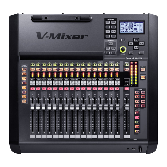
Roland M-200i V-mixer Owner's Manual
Live mixing console
Hide thumbs
Also See for M-200i V-mixer:
- Brochure & specs (12 pages) ,
- Reference manual (6 pages) ,
- Setup manual (7 pages)
Table of Contents
Advertisement
Quick Links
Download this manual
See also:
Reference Manual
Owner's Manual
Before using this unit, carefully read the sections entitled: "USING
THE UNIT SAFELY" (p. 3–5), and "IMPORTANT NOTES" (p. 6–7).
These sections provide important information concerning the proper
operation of the unit. Additionally, in order to feel assured that you
have gained a good grasp of every feature provided by your new unit,
Owner's manual should be read in its entirety. The manual should be
saved and kept on hand as a convenient reference.
Copyright © 2012 ROLAND CORPORATION
All rights reserved. No part of this publication may be reproduced in any form
without the written permission of ROLAND CORPORATION.
Advertisement
Chapters
Table of Contents

Related Manuals for Roland M-200i V-mixer


Summary of Contents for Roland M-200i V-mixer
- Page 1 Owner’s manual should be read in its entirety. The manual should be saved and kept on hand as a convenient reference. Copyright © 2012 ROLAND CORPORATION All rights reserved. No part of this publication may be reproduced in any form without the written permission of ROLAND CORPORATION.
- Page 3 008e do so). Refer all servicing to your retailer, the Use only the included power cord nearest Roland Service Center, or an authorized ● Use only the attached power-supply cord. Also, Roland distributor, as listed on the “Infor- the supplied power cord must not be used with mation”...
- Page 4 Do not use overseas ● place containers with liquid on unit Before using the unit in a foreign country, consult with your retailer, the nearest Roland ● Do not place containers containing liquid ( e.g., Service Center, or an authorized Roland ) on this product.
- Page 5 101b 110b Place in a well ventilated location If there is a possibility of lightning strike, disconnect the AC ● The unit and the AC adaptor should be located adaptor from the outlet so their location or position does not interfere ●...
-
Page 6: Power Supply
If you want to keep your settings, you must save that it may not be possible to restore the data, and Roland your settings before turning the power off. - Page 7 IMPORTANT NOTES 558a ● ● To avoid disturbing your neighbors, try to keep the unit’s USB memory (USB flash Memory and USB flash drive) does not volume at reasonable levels. You may prefer to use work via USB hub. headphones, so you do not need to be concerned about those ●...
-
Page 8: Table Of Contents
Contents Introduction ..................11 Check the included items ..............................11 Conventions used in this manual ............................11 Basic knowledge about REAC .............................11 Placement....................................13 Turning the power on/off..............................15 About the internal lithium battery............................16 About USB memory ................................16 Explanation of the panels ..............17 Top panel/Front panel................................17 Rear panel....................................22 Basic operation .................. - Page 9 Metering ....................59 About the meters..................................59 METER FUNCTION screen ..............................59 DCA groups................... 60 About DCA groups..................................60 Accessing the DCA GROUP screen ............................60 DCA GROUP FUNCTION screen ............................61 Mute groups ..................62 About mute groups ................................62 MUTE GROUP FUNCTION screen............................62 Effects,GEQ,External effects ............... 64 About effects.....................................64 About inserting an external effects device ........................64 EFFECTS screen..................................65...
- Page 10 Dimensions ..................................... 124 Effect types ..................125 Reverb....................................... 125 Delay......................................130 Modulation ..................................... 134 Channel strip ..................................136 Pitch shift....................................138 GEQ ......................................139 Roland vintage effects ................................ 140 The amount of RAM access for each FX algorithm....................141 Index ....................145...
-
Page 11: Introduction
About REAC • The M-200i itself The REAC (Roland Ethernet Audio Communication) interface is • Power cord the core of a V-Mixing system. It uses a proprietary protocol * Use only the power cord that was included with the M-200i. - Page 12 Introduction Ethernet connectors REAC connections Ethernet cables use RJ45 plugs. REAC equipment provides an RJ45 connector for each REAC port. Here is a typical example of connections using the S-1608. fig.RJ45andREAC-j.eps When connecting REAC devices to each other, the REAC mode of one device must be set to REAC master, and the REAC mode of the other must be set to REAC slave.
-
Page 13: Placement
When the unit is grounded, a slight hum may occur, depending on the particulars of your installation. If you are unsure of the connection method, contact the nearest Roland Service Center, or an authorized Roland distributor, as listed on the Information leaflet. Unsuitable places for connection •... - Page 14 Introduction Attaching the power cord hook When installing in a Rack As shown in the illustration, fit the power cord hook over the power cord. When installing in a Rack, the M-200i should be used only fig.cord-hook1.eps with the optional rackmount angle brackets, RA-10U. RA-10U Included items •...
-
Page 15: Turning The Power On/Off
Introduction If you move the cursor to 8 HOURS (ENABLE “AUTO OFF”) and Turning the power on/off press [ENTER], the auto off function is kept enabled. Turning the power on This screen will not appear if the auto off function is turned “OFF”... -
Page 16: About The Internal Lithium Battery
Introduction ig.battery-panel2.eps About the internal lithium battery The M-200i has an internal lithium battery that backs up the clock function and the mixer settings. If this battery runs down, the clock function and the feature that provides for the reinstatement of the mixer settings that existed prior to switching off the power will no longer operate correctly. -
Page 17: Explanation Of The Panels
Explanation of the panels Top panel/Front panel fig.TopPanelGuide.eps Fader module section p. 18 LAYER section p. 18 Main fader module p. 19 Display p. 19 CHANNEL EDIT section p. 19 DISPLAY section p. 20 Screen controller section p. 20 SENDS ON FADER section p. -
Page 18: Fader Module Section
Explanation of the panels Fader module section LAYER section fig.FaderModSectGuide.eps fig.LayerSectGuide.eps This section lets you select the channel layer to be assigned to the fader module section. The button of the currently assigned channel layer lights up. USER2 layer button USER1 layer button These assign user fader layer 1 or user fader layer 2 to the fader module section. -
Page 19: Main Fader Module
Explanation of the panels Main fader module Display fig.MainFaderModGuide.eps This display indicates the mixer parameters and system settings, as well as displaying a list of the meters. CHANNEL EDIT section fig.DisplayGuide.eps In this section, you can access the respective screens for working with the parameters of the currently selected channel. -
Page 20: Display Section
Explanation of the panels SCENE button DISPLAY section This button accesses the SCENE screen, where you manage fig.FunctionSectGuide.eps the scene list. “Scene memory” (p. 74) USB REC button This button accesses the RECORDER screen for making recorder settings and managing the song list. METER button “USB memory recorder”... -
Page 21: Sends On Fader Section
Explanation of the panels SENDS ON FADER section PHONES jacks fig.MeterBtn.eps You can connect a set of headphones to these jacks, and use them to monitor the MONITOR L/R audio signal. • Miniature stereo phone type • Stereo 1/4-inch phone type The minimum impedance of headphones that you can connect is 16Ω... -
Page 22: Rear Panel
Explanation of the panels Rear panel fig.RearPanelGuide.eps 10 11 INPUT jacks p. 23 ASSIGNABLE OUTPUT jacks p. 23 MAIN OUTPUT jacks p. 24 AES/EBU OUT jack p. 24 REAC port p. 24 LAN connector p. 24 USB MEMORY connector p. 24 USB WLAN ADAPTOR connector p. -
Page 23: Input Jacks
Explanation of the panels INPUT jacks ASSIGNABLE OUTPUT jacks fig.ConsInJackGuide.eps fig.ConsOutJackGuide.eps ASSIGNABLE OUTPUT 1 – 6 jacks These are balanced XLR-3-32 male output jacks for outputting analog audio signals. By default, AUX1 through 6 are patched to these jacks. INPUT 1 – 16 jacks These are balanced XLR-3-31 female input jacks for inputting analog audio signals from microphones or line level This instrument is equipped with balanced (XLR) type jacks. -
Page 24: Aes/Ebu Out Jack
Explanation of the panels MAIN OUTPUT jacks LAN connector fig.REACPortGuide.eps You can use this connector to attach a Wireless LAN router for connection to an iPad. “LAN setting” (p. 101) These are balanced XLR-3-32 male output jacks for outputting analog audio signals. USB MEMORY connector By default, MAIN L/R is patched to these jacks. -
Page 25: Dock Cable Connector
If you are unsure of the connection method, contact the nearest Roland Service Center, or an authorized Roland distributor, as listed on the “Information” leaflet. -
Page 26: Basic Operation
Basic operation Basic panel operations Selecting the channel layer Use the buttons of the LAYER section to select the channel layer to be controlled by the fader module section. Each channel layer assigns the following channels to the fader module section: Channel layer Channels USER 2... -
Page 27: Screen Operations
Basic operation Screen operations Button operations Buttons on the screen are used to turn a function on or off, to Basic screen structure execute a command, or to access a screen. To operate a button, move the cursor to the desired button and press [ENTER]. ON/OFF buttons These are used to turn a parameter or function on or off. -
Page 28: List Operations
Basic operation List operations Copying channel settings to the clipboard Channel settings can be saved on the clipboard. At the editing screen for the desired channel, access the FUNCTION screen. The selected item in a list is highlighted. Use the up/down keys or the value dial to select a different item. -
Page 29: Pasting Channel Settings From The Clipboard
Basic operation When using the COPY function on the AUX/MTX/MAIN CHANNEL EDIT screen, the following parameters for the currently selected channel are copied: Attenuator Comp Compressor (when compressor is selected) 4-band EQ Fader Fader Balance Balance A message announcing the completion of the paste operation is Limiter Limiter (when limiter is selected) displayed. -
Page 30: Library Operations
Basic operation Verify that the desired channel, effect, or patchbay is Library operations displayed. At the library data list, select the desired number, then You can store settings for many of the functions of the M-200i press [ENTER]. A popup appears. using LIBRARIES. - Page 31 Basic operation A message prompting you to confirm the operation is Storing data to a library displayed. Access the desired LIBRARY screen. Pressing the [ENTER] button stores the data to the library and closes the popup. Pressing [EXIT] cancels the library data-store operation. If the “SCENE/LIB STORE”...
- Page 32 Basic operation Locking/unlocking library data Clearing data from a library You can lock user data to prevent from being accidentally Access the desired LIBRARY screen. overwritten. Access the desired LIBRARY screen. Verify that the desired channel, effect, or patchbay is displayed.
-
Page 33: Editing A Name
Basic operation Editing the name of library data Editing a name You can assign a name of up to twelve characters to user data. This section describes operations common to the NAME EDIT screens. Access the desired LIBRARY screen. Use the left/right cursor buttons to select a character. Verify that the desired channel, effect, or patchbay is Use the value dial to change the character. -
Page 34: Input Channel Operations
Input channel operations About the input channels The input channels process the audio signals from the input jacks and internal ports, and send them to the MAIN, AUX, and MTX buses. fig.InBlkDia.eps MAIN SOLO INPUT 1 2 3 4 5 6 7 8 1 2 3 4 P ATCHBAY CH 1–32... -
Page 35: Accessing The Channel Edit Screen
Input channel operations PAD button Accessing the CHANNEL EDIT This turns the pad on/off. Turning this on lowers the input screen sensitivity of the preamp by 20 dB. In the LAYER section, press [CH1-16] or [CH17-32] to The preamp circuit in the M-200i has no pad. assign the input channels to the fader module section. - Page 36 Input channel operations Dynamics Fader GATE button This turns the gate/expander on/off. This adjusts the send level to MAIN in a range of -Inf dB to For information on editing gate/expander parameters, refer to +10.0 dB. “Gate/expander operations” (p. 44). COMP button You can make more-detailed settings by holding down [FUNC] and operating the value dial.
-
Page 37: Channel Function Screen
Input channel operations CHANNEL FUNCTION screen Stereo-linking channels Adjacent odd-numbered and even-numbered channels can be Access the CHANNEL EDIT screen for the desired channel. stereo-linked so that their parameters have the same settings. This is convenient when you're dealing with stereo sources. Press [FUNC] to access the CHANNEL FUNCTION screen. -
Page 38: Mute Groups
Input channel operations Changing the patching for a channel Selecting the position from which the channel's signal is sent as the direct out You can change the patchbay setting for a selected channel. signal Access the CHANNEL FUNCTION screen for the desired channel. -
Page 39: Aux, Mtx, Main Operations
AUX, MTX, MAIN operations About AUX, MTX, MAIN The AUX and MAIN process the mixed audio signals from the input channels, and send them to the output ports. MTX (MATRIX) process a mix of the audio signals from input channels, AUX1-8, and MAIN, and send them to the output ports. fig.OutBlkDia.eps MAIN SOLO... -
Page 40: Accessing The Channel Edit Screen
AUX, MTX, MAIN operations • ATT (Attenuator) Accessing the CHANNEL EDIT This adjusts the input level. screen • EXT FX INSERT (External Effect insert) These ports let you use the rear panel INPUT17–20 and In the LAYER section, press [AUX/MTX] to assign the ASSIGNABLE OUTPUT 7-10 ports to insert external effects output channels to the fader module section. - Page 41 AUX, MTX, MAIN operations CHANNEL EDIT screen Attenuator EQ graph This shows the approximate response of the EQ. ATT knob EQ button This adjusts the input level of the channel in a range of -48.0 This turns the 4-band EQ on/off. dB to 0.0 dB.
-
Page 42: Channel Function Screen
AUX, MTX, MAIN operations Channel meter CHANNEL FUNCTION screen Access the CHANNEL EDIT screen for the desired channel. Press [FUNC] to access the CHANNEL FUNCTION screen. This indicates the signal level of the channel. For a stereo- linked channel, two meters (L and R) are shown. The level detection point is according to the setting in the METER screen. - Page 43 AUX, MTX, MAIN operations Stereo-linking AUX/MTX Changing the patching for a channel You can stereo-link adjacent odd-numbered and even-numbered You can change the patchbay setting for a selected channel. AUX/MTX so that their parameters have the same settings. Access the CHANNEL FUNCTION screen for the desired This is convenient when you want stereo output.
-
Page 44: Gate/Expander Screen
GATE/EXPANDER screen Gate/expander operations A gate/expander is provided on CH1–32, and can be used as a gate, an expander, or a ducking processor. A gate applies a user-adjustable level of attenuation (RANGE) to input signals that are lower than the threshold level. ffig.GateCurve.eps INPUT SIGNAL OUTPUT SIGNAL... - Page 45 GATE/EXPANDER screen Gate GATE/EXPANDER screen fig.PopGateGuide2.eps In the fader module section, press [SEL] to select the desired channel. In the CHANNEL EDIT section, press [GATE]. THRESH knob This adjusts the threshold level in a range of -80.0 dB–0.0 dB. RANGE knob This adjusts the RANGE in a range of -Inf dB–0.0 dB.
- Page 46 GATE/EXPANDER screen Expander Ducking fig.PopExpGuide.eps fig.PopDuckGuide.eps THRESH knob THRESH knob This adjusts the threshold level in a range of -80.0 dB–0.0 dB. This adjusts the threshold level in a range of -80.0 dB–0.0 dB. RATIO knob RANGE knob This adjusts the RATIO in a range of 1.00:1–INF:1 (14 steps). This adjusts the RANGE in a range of -Inf dB–0.0 dB.
-
Page 47: Gate Function Screen
GATE/EXPANDER screen GATE FUNCTION screen Selecting the type of GATE/EXPANDER Access the GATE FUNCTION screen. Access the GATE/EXPANDER screen for the desired channel. Select “TYPE SELECT“ and press [ENTER]. Press [FUNC] to access the GATE FUNCTION screen. GATE TYPE SELECT screen appears. The operations available at the GATE FUNCTION screen are as Select GATE, EXPANDER, or DUCKING as the GATE type, follows:... - Page 48 GATE/EXPANDER screen Selecting the key-in signal Using the key-in filter The key-in signal used by the gate is taken from the post-HPF Access the GATE FUNCTION screen. point of the channel itself or from any of the following sources: Select “KEY-IN FILTER“ and press [ENTER] to access the •...
-
Page 49: Compressor/Limiter Screen
COMPRESSOR/LIMITER screen Compressor/Limiter operations Compressors are provided on CH1-32, AUX 1-8, MTX1-4 and MAIN L/R. They apply a user-adjustable ratio of attenuation to input signals that exceed the threshold level. fig.CompCurve.eps INPUT SIGNAL (KNEE=HARD, GAIN=0.0dB, AUTO GAIN=OFF) OUTPUT SIGNAL THRESHOLD RATIO INPUT LEVEL Limiters are provided on each AUX1-8, MTX1-4, and MAIN L/R. -
Page 50: Compressor Screen
COMPRESSOR/LIMITER screen COMPRESSOR screen Accessing the COMPRESSOR screen In the fader module section, press [SEL] to select the desired channel. In the CHANNEL EDIT section, press the [COMP] button. On button This turns the COMPRESSOR on/off. The COMPRESSOR screen appears. IN meter This shows the input level of the compressor. -
Page 51: Comp Function Screen
COMPRESSOR/LIMITER screen COMP FUNCTION screen The compressor will narrow the dynamic range, because it Access the COMP screen for the desired channel. reduces the output of incoming signals that exceed the threshold level. Press [FUNC] to access the COMP FUNCTION screen. If AUTO GAIN is on, the upper limit of the output level when ATTACK time is 0 ms is boosted while maintaining 6 dB of headroom from clip level (0 dB), thus maximizing the... - Page 52 COMPRESSOR/LIMITER screen Using the key-in filter Changing between COMPRESSOR/ LIMITER Access the COMP FUNCTION screen. You can select either compressor or limiter on AUX1 through 8, Select “KEY-IN FILTER“ and press [ENTER] to access the MTX1 through 4, and MAIN L and R. COMP KEY-IN FILTER screen.
-
Page 53: Limiter Screen
COMPRESSOR/LIMITER screen LIMITER screen Accessing the LIMITER screen In the fader module section, press [SEL] to select the Limiters are provided on each AUX1 through 8, MTX1 through 4, desired channel. and MAIN L and R. In the CHANNEL EDIT section, press [COMP]. ON button This turns the LIMITER on/off. -
Page 54: Limiter Function Screen
COMPRESSOR/LIMITER screen LIMITER FUNCTION screen Access the LIMITER screen for the desired channel. Press [FUNC] to access the LIMITER FUNCTION screen. The following functions are available at the LIMITER FUNCTION screen. TYPE SELECT This selects COMPRESSOR or LIMITER as the compressor type. -
Page 55: 4-Band Eq
4-BAND EQ 4-band EQ operations A 4-band EQ is provided on each CH1 through 32, MAIN L and R, AUX1 through 8, and MTX1 through 4 channel. About 4-band EQ for CH1-32 The LO and HI bands provide shelving-type or peaking-type filters, and the LO-MID and HI-MID bands provide peaking-type filters. Also, 12-dB/octave high-pass filters that pass the region higher than the specified frequency are provided for CH1 through 32. -
Page 56: Eq Function Screen
4-BAND EQ EQ FUNCTION screen Access the EQ screen for the desired channel. Press [FUNC] to access the EQ FUNCTION screen. The operations available at the EQ FUNCTION screen are as follows: FLAT This sets the gain to 0.0 dB for each band. LO EQ TYPE Selects as the EQ TYPE for the LO band. -
Page 57: Aux/Mtx Send
AUX/MTX send AUX/MTX send operations (CH1–32) This sends audio signal from CH1 through 32 to AUX1 through 8, and MTX1 through 4. fig.InBlkSends.eps MAIN SOLO 1 2 3 4 5 6 7 8 1 2 3 4 CH 1–32 PRE EQ PRE FADER POST FADER MUTE FADER... -
Page 58: Sends Screen
AUX/MTX send SENDS screen SENDS FUNCTION screen In the fader module section, press [SEL] to select the Access the SENDS screen for the desired channel. desired channel. Press [FUNC] to access the SENDS FUNCTION screen. In the CHANNEL EDIT section, press the [SEND] button. The functions available at the SENDS FUNCTION screen are as The SENDS screen is displayed. -
Page 59: Metering
Metering About the meters METER FUNCTION screen This section describes the METER screen, where you can view a To change the level detection point of the meter and make peak list of channel levels. hold settings, you use the METER FUNCTION screen. Access the METER screen. -
Page 60: Dca Groups
DCA groups About DCA groups Accessing the DCA GROUP screen DCA grouping is a function that lets you make relative In the DISPLAY section, press [DCA]. adjustments to the output level of channels so that the level of multiple channels belonging to a group can be controlled together. -
Page 61: Dca Group Function Screen
DCA groups DCA GROUP FUNCTION screen Assigning channels to DCA groups Access the DCA GROUP screen. Selecting “GROUP ASSIGN“ at the CHANNEL EDIT FUNCTION Press [FUNC] to access the DCA GROUP FUNCTION screen also lets you assign channels to DCA groups. For details, screen. -
Page 62: Mute Groups
Mute groups About mute groups MUTE GROUP FUNCTION screen Mute grouping is a function that lets you control the mute status Access the MUTE GROUP screen. of multiple channels belonging to a mute group. Press [FUNC] to access the MUTE GROUP FUNCTION A channel can belong to more than one mute group. - Page 63 Mute groups Specifying a name for a mute group You can specify a name for each mute group. A name of up to six characters can be specified. You use the NAME EDIT screen to edit the name. Access the MUTE GROUP FUNCTION screen. Select one from among “MUTE1-4 NAME EDIT“...
-
Page 64: Effects,Geq,External Effects
Effects,GEQ,External effects The M-200i is provided with four programmable effects processors and four mono 31-band GEQs. You can also use the input and output jacks on the rear panel to insert up to four external effect processors into channels. About effects fig.EffectDia.eps EFFECTS FX INPUT... -
Page 65: Effects Screen
Effects,GEQ,External effects EXT FX1-4 EFFECTS screen In the top panel's DISPLAY section, press the [EFFECT] button. The EFFECTS screen appears. You can use the up and down cursor buttons to change the effect number. FX1-4 INSERT indication This shows the input-source for the external effect. EXT FX ON button This enables or disables the EXT FX. -
Page 66: Effects Function Screen
Effects,GEQ,External effects EFFECTS FUNCTION screen Effect input/output settings Access the EFFECTS screen. You use the EFFECTS FUNCTION screen to select the input source and output destination for the effect. Press [FUNC] to access the EFFECTS FUNCTION screen. Setting the input source for an effect Access the EFFECTS FUNCTION screen. -
Page 67: Using An Effect Via Send/Return
Effects,GEQ,External effects Using an effect via send/return Specifying the effect return channel Access the EFFECTS FUNCTION screen. Effects such as reverb and delay are typically used in a send/ return configuration. Move the cursor to the FX3 L DESTINATION, and press [ENTER]. -
Page 68: Inserting An Effect Into A Channel
Effects,GEQ,External effects Inserting an effect into a channel Inserting an EXT FX into a channel Here we will explain the procedure for inserting the L side of FX1 into CH1. Here we will explain how to connect your external effects device Access the EFFECTS FUNCTION screen. -
Page 69: Editing Effect Parameters
Effects,GEQ,External effects Editing effect parameters FX EDIT FUNCTION screen Access the FX EDIT screen. You use the FX EDIT screen to manipulate effect parameters. Press [FUNC] to access the FX EDIT FUNCTION screen. Accessing the FX EDIT screen Access the EFFECTS screen. The operations available at the FX EDIT FUNCTION screen are as follows: Move the cursor to the EDIT button for the desired effect... - Page 70 Effects,GEQ,External effects Using the effect library RECALL This recalls the library data selected using the list. STORE This stores the library data selected using the list. You use the effect library to select the effect type. You can recall effect settings from the library, and store the current effect LOCK This locks the library data selected using the list.
-
Page 71: About Geqs
Effects,GEQ,External effects About GEQs The M-200i has four internal GEQs (GEQ1 through 4) separately GEQ FUNCTION screen from the stereo effects. GEQ1 through 4 can be inserted into CH1 through 32, MAIN L and Access the GEQ screen. R, AUX1 through 8, and MTX1 through 4. Press [FUNC] to access the GEQ FUNCTION screen. -
Page 72: Editing Geq Parameters
Effects,GEQ,External effects Editing GEQ parameters GEQ EDIT FUNCTION screen Access the GEQ EDIT screen for the desired channel. GEQ EDIT screen Press [FUNC] to access the GEQ EDIT FUNCTION screen. Access the GEQ screen Move the cursor to the EDIT button for the desired GEQ among “GEQ1-4“... - Page 73 Effects,GEQ,External effects Controlling a GEQ using the top-panel faders Access the desired GEQ EDIT FUNCTION screen. Move the cursor to the GEQ ON FADER and press [ENTER]. You can accomplish GEQ operations using the faders on the top panel. The range of corresponding faders is displayed on the screen.
-
Page 74: Scene Memory
Scene memory About Scene memory Scene memory is a function that lets you store mixer parameters as a scene, and recall them when desired. The M-200i can store 300 scenes in its internal memory, and you can assign a 16-character name to each scene. The following scene function is also provided: •... - Page 75 Scene memory Recalling a scene memory to the mixer Saving mixer parameters in a scene parameters (recall) memory (store) Access the SCENE screen. Access the SCENE screen. From the scene list, select the desired scene and press From the scene list, select the desired scene and press [ENTER].
-
Page 76: Scene Function Screen
Scene memory Locking/unlocking a scene Renaming a scene memory Access the SCENE screen. Access the SCENE screen. From the scene list, select the desired scene and press Select the scene memory that you want to rename, and [ENTER]. A popup appears. press [ENTER]. -
Page 77: Usb Memory Recorder
USB memory recorder About the USB memory recorder RECORDER screen The M-200i provides a two-track recorder function that uses USB You use the RECORDER screen to make settings for the USB memory. This function allows you to choose any two sources memory recorder. -
Page 78: Recorder Function Screen
USB memory recorder Pressing buttons executes the following action at RECORDER Using the USB memory recorder screens. Button Function Editing the song list This selects the previous WAV file.Holding this down during playback rewinds the WAV file being played. The song list shows the WAV files located in the “/RSS/M-400/ This selects the next WAV file.Holding this down SONGS“... - Page 79 USB memory recorder Move the cursor to the Moving the cursor to that you USB memory recorder input-source want to make the output destination and press [ENTER] to attach a check mark to it. settings Press [EXIT] to quit the screen. By default, the inputs of the USB memory recorder are specified as follows: Make the setting in the same way for R as well.
-
Page 80: Setup Screen
SETUP screen You use the SETUP screen to make a variety of settings for the M- • REAC 200i. This makes the settings for the M-200i's REAC port. Accessing the SETUP screen “REAC applications and settings” (p. 96) In the top panel's DISPLAY section, press [SETUP]. •... -
Page 81: Saving And Loading Mixer Settings
SETUP screen Loading mixer settings from USB memory Access the LOAD/SAVE screen. From the project file list, select the file you want to load and press [ENTER]. A popup appears. • INITIALIZE This accesses the INITIALIZE screen, where you can initialize the mixer settings (p. - Page 82 SETUP screen Saving mixer settings to USB memory It's a good idea to save your mixer settings, because in Access the LOAD/SAVE screen. the unlikely event that the M-200i should malfunction, this will allow you to move your settings to a backup M- Select the current directory, and press [ENTER].
-
Page 83: Locking The Console
SETUP screen Deleting mixer settings from USB Locking the console memory You can lock the console to prevent it from being operated. Access the LOAD/SAVE screen. If you turn off the power while the console is locked, the console is unlocked the next time you turn on the power. From the project file list, select the file you want to delete and press [ENTER]. -
Page 84: Initializing The Mixer Settings
SETUP screen Initializing the mixer settings Attempting to initialize the scenes or libraries when locked scenes or libraries exist makes a warning Access the SETUP screen. message like the following appear: Select “INITIALIZE“ and press [ENTER]. Moving the cursor to the KEEP LOCKED DATA and pressing [ENTER] initializes only the unlocked data, The INITIALIZE screen is displayed. -
Page 85: Managing Usb Memory
SETUP screen Managing USB memory Testing the speed of USB memory Here's how to test your USB memory's reading and writing speed The USB MEMORY screen is used to perform USB memory to verify whether it can be used by the USB memory recorder for management. -
Page 86: Input/Output Patchbay
Input/output patchbay Default setting of the input/output patchbay Default settings of the input patchbay When the M-200i is in its default state, the input patchbay is set as follows: Input channel Input port CH1–24 INPUT1–24 CH25–26 FX3 OUT L,R CH27–28 FX4 OUT L,R CH29–30 DOCK INPUT L,R... -
Page 87: Patchbay Operations
Input/output patchbay Patchbay operations If the “PATCHBAY CHANGE“ item in the CONFIRMATION section of User Preference (p. 94) is not in effect, no confirmation message is displayed in step 3. Accessing the PATCHBAY screen In the top panel's DISPLAY section, press [SETUP]. You can patch more than one channel to a single input jack. - Page 88 Input/output patchbay Editing the output patching Using the patchbay libraries Access the PATCHBAY screen. At the INPUT/OUTPUT PATCHBAY LIBRARY screen, you can store the settings for the current input or output patchbay and recall Select “OUTPUT PATCHBAY“ and press [ENTER]. the settings later.
-
Page 89: Talkback
Talkback About talkback fig.TB-OSCFlow.eps MAIN 1 2 3 4 5 6 7 8 1 2 3 4 TALKBACK / OSCILLATOR TALKBACK / OSC OUT TALKBACK / OSC OSC ON SELECT TALKBACK LEVEL INPUT 1 OSC ON INPUT 16 TO OUTPUT PATCHBAY FREQ LEVEL LR 1 2 3 4 5 6 7 8... -
Page 90: Talkback Function Screen
Talkback TALKBACK FUNCTION screen Access the TALKBACK screen. Press [FUNC] to access the TALKBACK FUNCTION screen. The following functions are available at the TALKBACK FUNCTION screen. MIC SELECT: This selects the input jack for connecting the mic to use for talkback. If you don't use talkback, select “NONE.“... -
Page 91: Oscillator
Oscillator About oscillator fig.TB-OSCFlow.eps MAIN 1 2 3 4 5 6 7 8 1 2 3 4 TALKBACK / OSCILLATOR TALKBACK / OSC OUT TALKBACK / OSC OSC ON SELECT TALKBACK LEVEL INPUT 1 OSC ON INPUT 16 TO OUTPUT PATCHBAY FREQ LEVEL LR 1 2 3 4 5 6 7 8... -
Page 92: Monitor/Solo
Monitor/Solo About monitoring fig.MonitorFlow.eps SOLO OUTPUT P ATCHBAY MONITOR MONITOR MONITOR SELECT SOLO MONITOR AUX 1 OUT LOGIC LEVEL AUX 8 OUT MONITOR OUT L DELAY MAIN OUT L MONITOR OUT R MAIN OUT R DELAY MONO OUT DIRECT OUT 1-32 MTX 1 OUT TALKBACK / OSC MTX 4 OUT... -
Page 93: Using The Monitor
Monitor/Solo INPUT AFL This selects the point from the signal is sent from Using solo CH1 through 32 to solo. If this is on, the post-pan signal of the channel is sent. If this is off, the pre- At the MONITOR FUNCTION screen, adjust the “SOLO fader signal is sent. -
Page 94: User Preference Settings
User Preference settings Here you can make the settings for the user fader layers, user STARTUP OPTION buttons and other user preferences. This specifies scenes and layers in effect on powerup. USER PREFERENCE screen The parameters are as follows: RECALL SCENE This specifies scenes in effect on powerup. -
Page 95: Editing The User Buttons
User Preference settings Editing the user buttons Selecting the Home screen The user buttons are a function for assigning desired functions to You can select either the CHANNEL EDIT screen or the METER buttons [1] through [8] in the USER button section (p. 21). screen to be the Home screen. -
Page 96: Reac Applications And Settings
REAC applications and settings REAC applications This chapter explains more advanced ways to use REAC. About the M-200i's REAC functionality For basic information about REAC, refer to “Basic knowledge about REAC” (p. 11) . The REAC port on the M-200i operates as the REAC master, the REAC slave, or the REAC split. -
Page 97: Reac Connection Examples
M-200i's REAC port to a computer. For details, refer to the following website: Set the M-200i's REAC port to be the REAC master. http://www.roland.com/professional/ • In this example, the REAC port uses input and output from the stage. -
Page 98: Reac Settings
REAC applications and settings Monitor/broadcast console setup Set the M-200i's REAC port to SPLIT. • In this example, the output from the FOH console's REAC B split is received by the M-200i's REAC port. For details about connection examples, refer to “REAC connection examples”... - Page 99 REAC applications and settings...
-
Page 100: Network
Network Network functions IP ADDRESS This indicates the IP address. You can connect a Wireless LAN router to the LAN connector on SETUP button the M-200i's rear panel and use a application that has wireless support (the M-200i Remote iPad application) to operate the M- This access the LAN screen. -
Page 101: Lan Setting
Network LAN setting Viewing settings for LAN Accessing the LAN screen Access the LAN screen. Access the NETWORK screen. Select “INFOMATION“ and press [ENTER]. Select “SETUP“ button on LAN section and press [ENTER]. The LAN INFOMATION screen is displayed. The LAN screen is displayed. You can view the following values: LAN settings STATUS... -
Page 102: Basic Settings For Wireless Lan
Network Basic settings for WIRELESS LAN Press the button on the USB adapter (separately What's the wireless LAN function? available WNA1100-RL). Attaching a wireless USB adapter (WNA1100-RL, available separately) to the M-200i's WLAN ADAPTOR connector lets you operate the M-200i remotely using an application that has wireless support (the M-200i Remote iPad application). -
Page 103: Making Detailed Settings For Wireless Lan
Network Making detailed settings for WIRELESS LAN • When you're using a Wireless LAN router that you've Accessing the WIRELESS LAN screen connected to in the past, the connection is made as soon as you select the router. If the connection is successful, the M- Access the NETWORK screen. - Page 104 Network Connecting using WPS You can make a connection to a Wireless LAN router by using WPS. You can also make the connection by pressing the button on the USB adapter (WNA1100-RL, available separately). For details of the procedure, refer to “Basic connection method (connecting using WPS)”...
- Page 105 Network Making the setting for WIRELESS ID Viewing settings for WIRELESS LAN Here you make the setting for WIRELESS ID. Access the WIRELESS LAN screen. This ID setting is shared by the LAN and WIRELESS LAN settings. Select “INFOMATION“ and press [ENTER]. What's a wireless ID? This determines the M-200i's device name and ad-hoc SSID that are displayed by the application making the...
-
Page 106: Remote
“M-200iRCS” software and the “M-200iRCS Users Guide” both. (PDF version) from the Roland website listed below. For details on using M-200iRCS, refer to the “M-200iRCS Users Guide.” In order to use MIDI, go to the REMOTE screen and set “RS-232C/ http://www.rolandsystemsgroup.net/... -
Page 107: Remote Settings
Remote Remote settings Setting the device ID You use the REMOTE screen to make remote settings. Access the REMOTE screen. Select “DEVICE ID“ and press [ENTER]. Accessing the REMOTE screen In the DISPLAY section, press [SETUP]. At the SETUP screen, select “REMOTE“ and press [ENTER]. You specify a device ID in a range of 1 to 32. -
Page 108: Midi Settings
Remote MIDI settings MIDI SEND SETTING screen Access the MIDI screen. Access the REMOTE screen. Select “SEND“ and press [ENTER]. Select “MIDI“ and press [ENTER]. The MIDI SEND SETTING screen is displayed. The MIDI screen appears. At the MIDI SEND SETTING screen, you can specify the MIDI data MIDI OUT/THRU items that the M-200i sends via its MIDI connectors. -
Page 109: Usb Midi Settings
Remote USB MIDI settings USB MIDI SEND SETTING screen Access the USB MIDI screen. Access the REMOTE screen. Select “SEND“ and press [ENTER]. Select “USB MIDI“ and press [ENTER]. The USB MIDI SEND SETTING screen is displayed. The USB MIDI setting screen appears. At the USB MIDI SEND SETTING screen, you can specify the MIDI RECEIVE data items that the M-200i sends via its MIDI connectors. -
Page 110: V-Link Settings
Remote V-LINK settings RS-232C settings Access the REMOTE screen. Access the REMOTE screen. Select “V-LINK“ and press [ENTER]. Select “RS-232C RATE“ and press [ENTER]. The V-LINK screen appears. The RS-232C RATE screen appears. Select the RS-232C communication speed and press V-LINK [ENTER]. -
Page 111: System Settings
System settings DELAY UNIT Accessing the SYSTEM screen This selects the unit used for delay at the CHANNEL EDIT screens (AUX, MTX, or MAIN) and the MONITOR screen. In the top panel's DISPLAY section, press [SETUP]. The selection items are as follows: At the SETUP screen, select “SYSTEM“... -
Page 112: Adjusting The Brightness Of The Display And Panel
System settings Adjusting the brightness of the Date&time setting display and panel Use the DATE&TIME popup of the SYSTEM screen to set the date and time. You use the DISPLAY/PANEL screen to adjust the settings of the Access the SYSTEM screen. panel and display. -
Page 113: Other Settings
System settings Other settings Never turn off the power to the M-200i before initialization finishes. Initializing the M-200i's internal memory Turn off the power. This initializes the following items, returning them to their factory-default settings: • System settings • Network settings •... - Page 114 System settings Fader calibration Clearing Fader calibration If the fader positions are no longer aligned with the index This clears the calibration setting of all faders. markings of the top panel, you can use the Fader Calibration Hold down [SETUP] in the DISPLAY section and turn on function to correct the misalignment.
-
Page 115: Appendix
Appendix User button functions FUNCTION PARAM1 PARAM2 Explanation NONE Unlit SCENE PREV RECALL Lit while held Recalls the scene of the previous number NEXT RECALL Lit while held Recalls the scene of the next number DIRECT RECALL 000–299 Lit while held Recalls the scene of the specified number UNDO RECALL Lit if UNDO is available... -
Page 116: Error Message List
Appendix Error message list Message Explanation xxx is used for EXT FXx Port xxx is being used by EXT FXx. Do you want to disable EXT FXx? Do you want to disable it? Cannot operate the USB memory. The device connected to the USB MEMORY connector used more than the maximum allowable electrical current. It exceeds the power capability. -
Page 117: Troubleshooting
Appendix Troubleshooting Can’t input successfully from REAC; Overall operation noise is heard No sound If REAC devices are connected incorrectly or if the REAC mode setting is incorrect, it will not be possible to input from REAC, and ● A device is not powered on. noise may be heard. - Page 118 Appendix ● Communication is unstable. Network • Because the connection uses radio waves, communication can become unstable in certain circumstances. When communication is unstable, response can be sluggish in some cases. The methods described below can bring about improvement ● A connection to the Wireless LAN router cannot be made.
-
Page 119: Pin Configuration Diagrams
Appendix Other Pin configuration diagrams Insufficient volume from a device Cat5e Ethernet cables connected to the output jacks (RJ45 EtherCon type connectors) ● You’re using a cable that contains a built-in resistor. Cat5e crossover cables Insufficient volume from a device (REAC cables SC-W100S) connected to the INPUT jacks fig.PinCat5eCross.eps... -
Page 120: Requirements For Switching Hubs
Appendix Requirements for switching hubs Switching hubs used to connect REAC devices must meet the following conditions: • We recommend a switching hub that supports 1000BASE-T (IEEE 802.3ab, Gigabit Ethernet) • 100BASE-TX interface must be supported (IEEE 802.3u, Fast Ethernet) •... -
Page 121: Main Specifications
Appendix Main specifications M-200i: LIVE MIXING CONSOLE Mixing Channels INPUT : 32 channels BUS : MAIN L/R, 8 AUX buses, 4 MATRIX buses OUTPUT: 14 ports (Max 54 ports When using REAC Devices ) Signal Processing AD/DA Conversion: 24 bit Sample Rate: 48.0 kHz or 44.1 kHz Frequency Response ASSIGNABLE OUTPUT jacks (1 to 10): -2 dB / +0 dB (20k ohms load, +4 dBu, typ.) - Page 122 Appendix Output Impedance ASSIGNABLE OUTPUT jacks (1 to 10): 600 ohms (typ.) MAIN OUTPUT jacks (L, R): 600 ohms (typ.) PHONES jack: 49 ohms (typ.) Recommended Load Impedance ASSIGNABLE OUTPUT jacks (1 to 10): 10 k ohms or greater MAIN OUTPUT jacks (L, R): 10 k ohms or greater PHONES jack: 40 ohms or greater Minimum Load Impedance PHONES jack: 16 ohms...
- Page 123 Wireless USB Adapter:WNA1100-RL USB Flash Memory * Use USB Flash Memory sold by Roland. We cannot guarantee operation if other products are used. * 0dBu=0.775Vrms * In the interest of product improvement, the specifications and/or appearance of this unit are subject to change without prior notice.
-
Page 124: Dimensions
Appendix Dimensions Dimensions are shown in millimeters. -
Page 125: Effect Types
Effect types Reverb Types of sound fig.RevExp01.eps early reflections reverberation direct sound source listener The sound you normally hear is divided into three types: “direct sound,” “early reflections,” and “reverberation.” The “direct sound” is the sound that reaches the listener directly from the source. “Early reflections” are sounds that have reflected one to several times from the walls or other surfaces of the room. - Page 126 Appendix sound begins to be attenuated St.REVERB (Stereo Reverb) Value: 20 Hz–2.00 kHz fig.AlgoStRev.eps HI FREQ DAMP GAIN Input L Output L High-frequency attenuation of the reverb sound Value: -36.0–0.0 dB Stereo 4 Band EQ Reverb HI FREQ DAMP FREQ Frequency at which the high-frequency region of the reverb sound begins to be attenuated Input R...
- Page 127 Appendix LO-MID FREQ LPF2 (Low-Pass Filter 2) Center frequency of the Lo-Mid band (*1) A sharper response curve than LPF1 Freq: Valid Gain: — Q: Valid Value: 20 Hz–20.00 kHz HPF2 (High-Pass Filter 2) LO-MID Q A sharper response curve than HPF1 Steepness of the frequency response curve at the Lo-Mid band Freq: Valid Gain: —...
- Page 128 Appendix HI CUT FREQ REVERB+GATE Frequency at which the high-frequency region of the reverb sound will be cut fig.AlgoRevwGate.eps Value: 200 Hz–20.00 kHz Input L Output L WET (Wet Level) 4 Band EQ Gate Level of the reverb sound Reverb Value: -INF–+6.0 dB Key-In...
- Page 129 Appendix HI-MID FREQ GATE Center frequency of the Hi-Mid band (*1) GT SW (GATE switch) Value: 20 Hz–20.00 kHz Turns the gate on/off HI-MID Q Value: OFF, ON Steepness of the frequency response curve at the Hi-Mid band center frequency (*1) GT MODE (Gate mode) Value: 0.36–16.00...
-
Page 130: Delay
Appendix Delay DELAY x2 As delay units, you can use msec, Meter, Feet, Frame (24, 25, fig.AlgoDualDelay.eps 29.97, 30fps), or Note. The M-200i’s delay is based on msec units, Input A Output A and simply changing the delay unit parameter will not change the delay time in msec units. - Page 131 Appendix WET POSITION FEEDBACK TIME (Feedback time) The wet position specifies how the delay’s wet signal is related Time until the delayed sound is returned to the input of the to the position of the DPF (Damp Filter). delay Value Value: 0.0–2700 ms PRE DAMP:...
- Page 132 Appendix Value: 20 Hz–2.00 kHz M.TAP DELAY (Multi Tap Delay) HI FREQ DAMP GAIN fig.AlgoMTPDly.eps Output L High-frequency attenuation of the delay sound Input L Value: -36.0–0.0 dB Pan 1 HI FREQ DAMP FREQ Pan 2 Frequency at which the high-frequency region of the delay sound begins to be attenuated Value: 200 Hz–20.00 kHz...
- Page 133 Appendix X.MOD DELAY (Cross-modulation Delay) Cross feedback will feed back the effect sound to the opposite input (left or right). fig.AlgoXModDelay.eps Input L Output L LO FREQ DAMP GAIN PRE DPF POSITION Low-frequency attenuation of the delay sound Delay L POST DPF Value: -36.0–0.0 dB...
-
Page 134: Modulation
Appendix Modulation St.FLANGER (Stereo Flanger) St.CHORUS (Stereo Chorus) fig.AlgoStFlang.eps fig.AlgoStCho.eps DIR SW Input L Output L DIR SW Input L Output L EFF SW EFF SW Chorus L Flanger L XMIX Chorus R EFF SW Flanger R Input R DIR SW Output R EFF SW This is a stereo-in, stereo-out chorus. - Page 135 Appendix Value: OFF, ON FB (Feedback) Amount of phaser sound that is returned to the input of the EFF SW (Effect switch) phaser Turns the effect sound on/off Value: -100–100 Value: OFF, ON XFB (Cross feedback) Amount of phaser sound that is returned to the opposite-side Feedback means returning the effect sound back into the input of the phaser input.
-
Page 136: Channel Strip
Appendix Channel strip EQ A/B CH STRIP x2 (Channel Strip x2) EQ SW (EQ switch) fig.AlgoDualChStrip.eps Turns the EQ on/off Input A Output A Enhancer/ Value: OFF, ON 4 Band EQ Delay De-esser Input B Output B EQ ATT (EQ attenuator) Enhancer/ 4 Band EQ Delay... - Page 137 Appendix HI-MID FREQ BPF (Band Pass Filter) Center frequency of the Hi-Mid band (*1) Passes the frequency region around FREQ. Freq: Valid Gain: — Q: Valid Value: 20 Hz–20.00 kHz BEF (Band Eliminate Filter) HI-MID Q Removes the frequency region around FREQ Steepness of the frequency response curve at the Hi-Mid band Freq: Valid Gain: —...
-
Page 138: Pitch Shift
Appendix filter is used as the wet signal. In this case, Pitch shift the damp filter is applied only to the delay feedback. POST DAMP: Takes the wet sound from after the damp P.SHIFTER x2 (Pitch Shifter x2) filter. fig.AlgoDualPS.eps the signal after passing through the damp Input A Output A... -
Page 139: Geq
Appendix fig.AlgoDualGEQ.eps Input A Output A 31 Band GEQ Input B THRU Output B This is a single-mono 31-band GEQ. ATT (Attenuator) Attenuator for the GEQ Value: -42.0–+15.0 dB 20 Hz Gain–20 kHz Gain Gain of each band Value: -15.0–+15.0 dB... -
Page 140: Roland Vintage Effects
Appendix Roland vintage effects RESONANCE SBF-325 (STEREO FLANGER SBF-325) Boosts the region around the center frequency specified by CENTER FREQ This is a stereo-in, stereo-out flanger that models the Roland SBF- Value: 0.0–10.0 325 Stereo Flanger. SHIFT MODE FEEDBACK Specifies the number of stages for the phaser... -
Page 141: The Amount Of Ram Access For Each Fx Algorithm
The amount of RAM access for fig.ScrSDD320.eps each FX algorithm This is a stereo-in, stereo-out chorus that models the Roland SDD- 320 Dimension D. The list of the amount of RAM access for each FX algorithm are as The SDD-320 was released in 1979, and became standard follows: equipment in many recording studios. - Page 142 CAUTION Danger of explosion if battery is Apparatus containing incorrectly replaced. Replace only with the same or Lithium batteries equivalent type recommended by the manufacturer. Discard used batteries according to the manufacturer’s instructions. ADVARSEL! VARNING Lithiumbatteri - Eksplosionsfare ved Explosionsfara vid felaktigt batteribyte. fejlagtig håndtering.
- Page 143 Compliance Information Statement Model Name : M-200i Type of Equipment : Audio Mixer Responsible Party : Roland Systems Group U.S. Address : 501 S.Eastern Avenue, Los Angeles, CA 90040-2938, U.S.A Telephone : (323) 890-3700 For the U.K. IMPORTANT: THE WIRES IN THIS MAINS LEAD ARE COLOURED IN ACCORDANCE WITH THE FOLLOWING CODE.
- Page 144 For EU Countries...
-
Page 145: Index
Index FX1 L SOURCE screen ..............68 FX1-4 EDIT screen ................. 69 AC adapter connector ..............25 FX1-4 LIBRARY screen ..............70 Action buttons ................27 FX3 DESTINATION screen ............67 AD-HOC Restrictions ..............104 AD-HOC screen ................104 AES/EBU OUT jack ................ 24 GATE ASSIGNABLE OUTPUT jacks ............ - Page 146 MIDI SEND SETTING screen ............ 108 USB MEMORY connector ............24 MONITOR FUNCTION screen ............ 92 USB MIDI RECEIVE SETTING screen ........109 MONITOR screen ................92 USB MIDI SEND SETTING screen ........... 109 MUTE GROUP FUNCTION screen ..........62 USB MIDI setting ................
- Page 148 Block Diagram TO EXTERNAL FX MAIN SOLO EXTERNAL FX OUT INPUT 1 2 3 4 5 6 7 8 1 2 3 4 OUTPUT PATCHBAY PATCHBAY MAIN L, R CH 1–32 POST ATT PRE COMP PRE EQ PRE FADER POST FADER POST LIMITER POST DELAY PREAMP POST ATT...
- Page 149 Roland, REAC, V-Mixer are either registered trademarks or trademarks of Roland Corporation in the United States and/or other countries. ● Cakewalk and SONAR are either registered trademarks or trademarks of Cakewalk, Inc. or Roland Corporation in the United States and/or other countries. ●...
Need help?
Do you have a question about the M-200i V-mixer and is the answer not in the manual?
Questions and answers