Table of Contents
Advertisement
Quick Links
Download this manual
See also:
Manual
IBM TotalStorage SAN32M-2
Installation and Service Manual
Service information: 2026 / 432, 32E
Read Before Using
This product contains software that is licensed under written license agreements. Your use of such software is subject to
the license agreements under which they are provided.
GC26-7763-01
Advertisement
Table of Contents

Related Manuals for IBM TotalStorage SAN32M-2


Summary of Contents for IBM TotalStorage SAN32M-2
- Page 1 IBM TotalStorage SAN32M-2 Installation and Service Manual Service information: 2026 / 432, 32E Read Before Using This product contains software that is licensed under written license agreements. Your use of such software is subject to the license agreements under which they are provided.
- Page 3 IBM TotalStorage SAN32M-2 Installation and Service Manual Service information: 2026 / 432, 32E GC26-7763-01...
- Page 4 ® Order publications through your IBM representative or the IBM branch office serving your locality. © Copyright International Business Machines Corporation 2005, 2006. All rights reserved. US Government Users Restricted Rights – Use, duplication or disclosure restricted by GSA ADP Schedule Contract...
-
Page 5: Table Of Contents
Task 2: Unpack, inspect, and install the Ethernet hub (optional)20 Unpack and inspect Ethernet hub..........20 Desktop installation..............20 Rack-mount installation.............22 Task 3: Unpack, inspect, and install the product......23 Unpack and inspect switch ............23 Desktop installation..............24 Rack-mount installation.............25 © Copyright IBM Corp. 2006... - Page 6 Task 4: Configure product at the EFCM Basic Edition interface (optional)..................... 26 Configure product identification ..........28 Configure date and time............28 Configure parameters ..............29 Configure fabric parameters ............. 31 Configure network information ..........32 Configure basic port information..........34 Configure port BB_Credit............
- Page 7 Configure product parameters..........73 Configure fabric parameters............75 Configure ports ................76 Configure SNMP .................78 Configure threshold alerts ............80 Enable EFCM Basic Edition and Telnet access......83 Configure, enable, and test e-mail notification.......83 Configure and enable Ethernet events........84 Configure, enable, and test call-home event notification..85 Configure security ..............86 Configure interswitch links ............87 Task 19: Back up configuration data..........87...
- Page 8 Set online state ................166 Block or unblock a port............167 Upgrade firmware..............168 Manage configuration data ............. 170 Repair procedures - SAN management application....173 Obtain Fabric Log information ..........174 Obtain Switch Log information..........175 Perform port diagnostics ............178 Collect maintenance data ............
- Page 9 ment ....................268 Industry Canada Class A Emission Compliance Statement..Avis de conformité à la réglementation d’Industrie Canada ... European Union (EU) Electromagnetic Compatibility Direc- tive....................268 Germany Electromagnetic Compatibility Directive ....269 People’s Republic of China Class A Electronic Emission State- ment ....................270 Korean Class A Electronic Emission Statement ....270 Japan VCCI Class A ITE Electronic Emission Statement ..270 Index...
- Page 10 SAN32M-2 Installation and Service Manual...
- Page 11 Configure Date and Time dialog box ............71 Configure Identification dialog box ............73 Configure Switch Parameters dialog box ........... 74 Configure Fabric Parameters dialog box ............ 75 Configure Ports dialog box ................77 © Copyright IBM Corp. 2006 xiii...
- Page 12 Configure SNMP dialog box ................ 79 New Threshold Alert dialog box (screen 1) ..........80 New Threshold Alert dialog box (screen 2) ..........81 New Threshold Alert dialog box (screen 3) ..........82 Email Event Notification Setup dialog box ..........83 InCD icon (unformatted CD) ................
- Page 13 Tables IBM products and SAN management documentation—E/OS ... xviii Factory-set defaults (product) ..............17 Installation task summary ................18 Operational states and symbols ..............64 Factory-set defaults ..................95 MAP summary ....................95 Event codes versus maintenance action ............96 MAP 100 event codes ...................
- Page 14 SAN32M-2 Installation and Service Manual...
-
Page 15: About This Book
Related publications Other publications that provide additional information about the switch include: • IBM TotalStorage Products in a SAN Environment Planning Manual, GC26-7675. • EFC Manager Software Release 8.7 User Manual, 620-000170. • SANavigator Software Release 4.2 User Manual 621-000013. -
Page 16: Ibm Products And San Management Documentation-E/Os
IBM and McDATA publications Some of the documentation that is applicable to IBM TotalStorage products is provided by McDATA Corporation. The documents often are identified by a McDATA product name that corresponds to the IBM product name. Table 1 lists the IBM product name, the corresponding McDATA product name, the applicable software, and the documentation that is relevant to the product. -
Page 17: Where To Get Help
• E/OS SNMP Support Manual (620-000131) • E/OS Command Line Interface User Manual (620-000134) Ordering manuals To order a printed copy of this publication, contact your IBM Branch office or you can locate (and purchase) books online at: http://www.elink.ibmlink.ibm.com/public/applications/ publications/cgibin/pbi.cgi? - Page 18 Department GZW 9000 South Rita Road Tucson, Arizona 85744-001 U.S.A When you send information to IBM, you grant IBM a nonexclusive right to use or distribute the information in any way it believes appropriate without incurring any obligation to you.
- Page 19 (G229-9054) publication, which is on the CD-ROM that accompanies this product. The following notices and statements are used in this document. They are listed below in order of increasing severity of potential hazards. Follow the links for more detailed descriptions and examples of the danger, caution, and attention notices in the sections that follow.
- Page 20 DANGER If the receptacle has a metal shell, do not touch the shell until you have completed the voltage and grounding checks. Improper wiring or grounding could place dangerous voltage on the metal shell. If any of the conditions are not as described, STOP. Ensure the improper voltage or impedance conditions are corrected before proceeding.
- Page 21 • Connect and disconnect cables as described below when installing, moving, or opening covers on this product or attached devices. To Disconnect: 1. Turn everything OFF (unless instructed otherwise). 2. Remove power cords from the outlet. 3. Remove signal cables from connectors. 4.
- Page 22 DANGER Multiple power cords (L003) Caution notices A caution notice calls attention to a situation that is potentially hazardous to people because of some existing condition. A caution notice can be accompanied by different symbols, as in the examples below: If the symbol is...
- Page 23 CAUTION The doors and covers to the product are to be closed at all times except for service by trained service personnel. All covers must be replaced and doors locked at the conclusion of the service operation. (C013) CAUTION The system contains circuit cards and/or assemblies that contain lead solder.
- Page 24 Product recycling This unit must be recycled or discarded according to applicable local and disposal and national regulations. IBM encourages owners of information technology (IT) equipment to responsibly recycle their equipment xxvi SAN32M-2 Installation and Service Manual...
- Page 25 IBM offers a variety of product return programs and services in several countries to assist equipment owners in recycling their IT products. Information on IBM product recycling offerings can be found on IBM’s Internet site at http://www.ibm.com/ibm/environment/products/prp.shtml...
- Page 26 In the United States, IBM has established a return process for reuse, recycling, or proper disposal of used IBM sealed lead acid, nickel cadmium, nickel metal hydride, and other battery packs from IBM Equipment.
-
Page 27: General Information
Chapter 1: General information The IBM TotalStorage SAN32M-2 switch provides 32 ports of low-cost and high-performance dynamic Fibre Channel connectivity for switched fabric or arbitrated loop devices. This function allows low-cost, low-bandwidth workgroup (edge) devices to communicate with mainframe servers, mass storage devices, or other peripherals, and ultimately be incorporated into an enterprise storage area network (SAN) environment. -
Page 28: Field Replaceable Units
Operators with a browser-capable PC and Internet connectivity can manage the switch through a firmware-resident Enterprise Fabric Connectivity Manager (EFCM) Basic Edition interface. The interface manages only a single switch, and provides a graphical user interface (GUI) that supports configuration, statistics monitoring, operation, and maintenance. -
Page 29: Sfp Transceiver
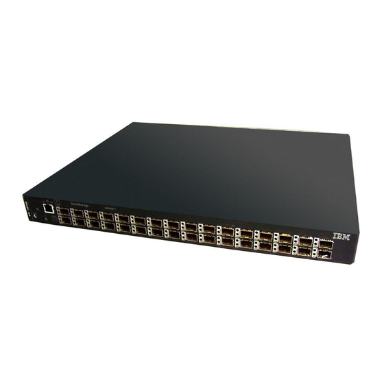
SAN32M-2 (front view) Figure 1 Figure 2 illustrates the rear of the switch and shows the: 1. RS-232 maintenance port. 2. Power supply assemblies with internal cooling fans (2). SAN32M-2 (rear view) Figure 2 SFP transceiver Singlemode or multimode fiber-optic cables attach to switch ports through SFP transceivers. -
Page 30: Power Supply Assembly
• At 500 meters (1.0625 Gbps) through 50-micron multimode fiber-optic cable. • At 300 meters (2.1250 Gbps) through 50-micron multimode fiber-optic cable. • At 150 meters (4.2500 Gbps) through 50-micron multimode fiber-optic cable. • At 300 meters (1.0625 Gbps) through 62.5-micron multimode fiber-optic cable. -
Page 31: Controls, Connectors, And Indicators
Controls, connectors, and indicators Controls, connectors, and indicators for the switch include the: • RESET button. • Ethernet LAN connector. • Green PWR and amber ERR LEDs. • Green and amber status LEDs associated with CRUs. • RS-232 maintenance port. •... -
Page 32: Power And System Error Leds
The connector provides two green LEDs. The left LED illuminates to indicate LAN operation at 10 Mbps. The right LED illuminates to indicate operation at 100 Mbps. Power and system error LEDs The PWR LED illuminates when the switch is connected to facility AC power and is operational (the product does not have a power switch). -
Page 33: Switch Specifications
Switch specifications This section lists physical characteristics, storage and shipping environment, operating environment, and service clearances. Physical Dimensions: characteristics Height: 4.1 centimeters (1.6 inches) or 1 rack unit Width: 43.7 centimeters (17.2 inches) Depth: 39.4 centimeters (15.5 inches) Weight: 6.8 kilograms (15.0 pounds) Power requirements: Input voltage: 90 to 264 VAC Input current: 0.35 amps at 208 VAC... -
Page 34: Maintenance Approach
Storage temperature: C to 60 C (34 F to 140 Shipping relative humidity: 5% to 100% Storage relative humidity: 5% to 80% Maximum wet-bulb temperature: C (84 Altitude: 12,192 meters (40,000 feet) Operating Temperature: environment C to 40 C (40 F to 104 Relative humidity: 8% to 80%... -
Page 35: Switch Management
• LEDs on the product front panel or CRUs illuminate to indicate a hardware malfunction. • An unsolicited SNMP trap message is received at a management workstation, indicating an operational state change or failure. • Event notification is received at a designated support center through an e-mail message or the call-home feature. -
Page 36: Management Server Specifications
Management server specifications This section summarizes minimum and recommended hardware specifications for a management server. Servers may ship with more enhanced hardware, such as a faster processor, additional random-access memory (RAM), or a higher-capacity hard drive. Minimum Minimum server specifications are: specifications ®... -
Page 37: Ethernet Hub (Optional)
24-Port Ethernet hub Figure 3 Hubs can be daisy-chained to provide additional connections as more switches (or other IBM-managed products) are installed on a network. Multiple hubs are daisy-chained by attaching RJ-45 Ethernet patch cables and configuring each hub through a medium- dependent interface (MDI) switch. -
Page 38: Error-Detection, Reporting, And Serviceability Features
Error-detection, reporting, and serviceability features The switch provides the following error detection, reporting, and serviceability features: • LEDs on switch CRUs and adjacent to Fibre Channel ports that provide visual indicators of hardware status or malfunctions. • Redundant CRUs and FRUs (SFP transceivers and integrated cooling fan and power supply assemblies) that are removed or replaced without disrupting switch or Fibre Channel link operation. -
Page 39: Tools And Test Equipment
• Automatic notification of significant system events (to support personnel or administrators) through e-mail messages or the call-home feature. NOTE: The call-home feature is not available through the EFCM Basic Edition. The call-home feature may not be available if the EFCM Basic application is installed on a customer-supplied platform. -
Page 40: Door Key
Door key Figure 4 • Loopback plug - A multimode (shortwave laser) or singlemode (longwave laser) loopback plug (Figure 5) is required to perform port diagnostic tests. Loopback plugs are shipped with the product, depending on the types of port transceivers installed. Loopback plug Figure 5 •... -
Page 41: Tools Supplied By Service Personnel
Null modem cable Figure 7 Tools supplied by service personnel The following tools should be supplied by service personnel: • Scissors or pocket knife - A sharp cutting edge (scissors or knife blade) is required to cut protective strapping when unpacking replacement CRUs. - Page 42 SAN32M-2 Installation and Service Manual...
-
Page 43: Installation Tasks
0.0.0.0 Installation task summary Table 3 summarizes installation tasks for the product, optional management server, and optional Ethernet hub. The table describes each task, states if the task is optional, and lists the page reference. © Copyright IBM Corp. 2006... -
Page 44: Installation Task Summary
Installation task summary Table 3 Task number and description Required or optional Page Task 1: Verify installation requirements Required. Task 2: Unpack, inspect, and install the Ethernet hub Perform task if hub is required to connect switch and (optional) management interface. Task 3: Unpack, inspect, and install the product Required. -
Page 45: Task 1: Verify Installation Requirements
• Fibre Channel SAN design and director, switch, and SAN router device connectivity are evaluated, and the related planning worksheet is complete. Refer to the IBM TotalStorage Products in a SAN Environment - Planning Manual (GC26-7675) for information. • Support is available for one of the following product management methods: —... -
Page 46: Task 2: Unpack, Inspect, And Install The Ethernet Hub (Optional)20
Ensure packaged items correspond to items listed on the enclosed bill of materials. 2. If any items are damaged or missing, within the United States and Canada, contact the IBM Quality Hotline toll-free 1-800-442-6773 or direct dial in other locations: 770-858-8459. Desktop installation To install and configure up to three Ethernet hubs on a desktop: 1. -
Page 47: Patch Cable And Mdi Selector Configuration
2. Position the first hub on a table or desktop as directed by the customer. Stack the remaining hubs on top of the first hub. Ensure the adhesive rubber pads on the underside of a hub align with the recesses on the top of the hub below. 3. -
Page 48: Rack-Mount Installation
5. Connect the AC power strip to facility power. Power for each hub switches on when the strip is connected to facility AC power. 6. Inspect the front panel of each hub. Ensure each green Power light-emitting diode (LED) illuminates. Rack-mount installation Perform the following steps to install and configure up to three Ethernet hubs in a SANC40M cabinet or customer-supplied 19-inch... -
Page 49: Task 3: Unpack, Inspect, And Install The Product
a. To connect the top and middle stacked hubs, connect an RJ-45 patch cable to port 24 of the top hub, then connect the cable to port 12 of the middle hub. b. To connect the bottom and middle stacked hubs, connect a second RJ-45 patch cable to port 24 of the middle hub, then connect the cable to port 12 of the bottom hub. -
Page 50: Desktop Installation
3. If any items are damaged or missing, contact the IBM Quality Hotline toll-free at 1-800-442-6773 within the United States and Canada. In other locations direct dial 770-858-8459. Desktop installation To install a switch on a desktop: 1. Remove the backing from the four adhesive rubber pads and apply the pads to the underside of the switch. -
Page 51: Rack-Mount Installation
8. If a POST error or other malfunction occurs, go to MAP 0000: Start to isolate the problem. 9. Perform one of the following: — If the switch is to be managed through the EFCM Basic Edition interface, go to Task 4: Configure product at the EFCM Basic Edition interface (optional). -
Page 52: Task 4: Configure Product At The Efcm Basic Edition Interface (Optional)
8. After successful POST completion, the PWR LED remains illuminated and all other front panel LEDs extinguish. 9. If a POST error or other malfunction occurs, go to MAP 0000: Start to isolate the problem. 10. Perform one of the following: —... -
Page 53: Hardware View
7. Click Switch Details. The Hardware View displays (Figure 10). Hardware View Figure 10 8. To configure the product from the EFCM Basic Edition interface, selectively perform the following tasks according to customer requirements: — Product - includes identification, date and time, parameters, fabric parameters, and network addresses. -
Page 54: Configure Product Identification
Configure product identification Perform this procedure to configure the product identification. The Name, Location, and Contact variables correspond respectively to the SNMP variables sysName, sysLocation, and sysContact, and are used by management workstations when obtaining product data. 1. Select Switch and Identification from the Configure menu at any view. -
Page 55: Configure Parameters
Date Time View Figure 12 a. Click Date fields that require change, and type numbers in the following ranges: • Month (MM): 1 through 12. • Day (DD): 1 through 31. • Year (YYYY): greater than 1980. b. Click Time fields that require change, and type numbers in the following ranges: •... -
Page 56: Parameters View
Parameters View Figure 13 b. At the Rerouting Delay field, check (enable) or uncheck (disable) the parameter. When enabled, traffic is delayed through the fabric by the user-specified error detect time out value (E_D_TOV). This delay ensures Fibre Channel frames are delivered to their destination in order. -
Page 57: Configure Fabric Parameters
NOTE: An ISL between fabric elements with identical domain IDs segments and prevents communication. h. At the ISL FSPF Cost Configuration field, select By Port Speed or Ignore Port Speed to calculate fabric shortest path first (FSPF) cost. • By Port Speed - The fastest fabric path is determined by port (ISL) speed. -
Page 58: Configure Network Information
Available selections are: • McDATA Fabric 1.0 - Select this option if the product is fabric-attached only to other IBM directors or switches operating in McDATA fabric mode. • Open Fabric 1.0 - Select this option (default) for managing... -
Page 59: Network View
• One product is installed on a dedicated LAN, network information (IP address, subnet mask, and gateway address) does not require change. • Multiple products are installed or a public LAN segment is used, network information must be changed to conform to the LAN addressing scheme. -
Page 60: Configure Basic Port Information
a. Close the EFCM Basic Edition interface and all browser applications. b. At the Windows desktop, click Start at the left side of the task bar. The Windows Workstation menu displays. c. At the Windows Workstation menu, sequentially select the Programs and Command Prompt options. -
Page 61: Configure Port Bb_Credit
Basic Information View Figure 16 d. Select from the drop-down list in the Type column to configure the port type. Available selections are fabric port (F_Port), expansion port (E_Port), generic port (G_Port), generic mixed port (GX_Port), and fabric mixed port (FX_Port). e. -
Page 62: Configure Port Npiv
default value is 12 credits per port. Perform this procedure to configure port receive BB_Credit: 3. Set all or a subset of user-specified ports offline. Refer to Set online state Block or unblock a port for instructions. 4. Select Ports and RX BB_Credit from the Configure menu at any view. -
Page 63: Snmp View
b. Select the appropriate Fibre Alliance management information base (FA MIB) from the FA MIB Version drop-down list. Valid selections are FA MIB Version 3.0 or FA MIB Version 3.1. Figure 17 SNMP View c. Click (check) the Enable Authentication Traps check box to enable transmission of SNMP trap messages to recipients. -
Page 64: Enable Cli
Enable CLI Perform this procedure to toggle (enable or disable) the state of the product’s command line interface. To change the CLI state: 1. Select CLI from the Configure menu at any view. The CLI View displays (Figure 18). CLI View Figure 18 2. -
Page 65: Configure Ssl Encryption
OSMS View Figure 19 2. Perform one of the following: • Click Enable to activate OSMS. • Click Disable to deactivate OSMS. 3. Click (check) the Enable Host Control check box to activate host control of the product. 4. Click OK to save and activate changes. Configure SSL encryption SSL is a protocol that encrypts internet communications. -
Page 66: Install Pfe Keys (Optional)
• Click Disable to deactivate software SSL. SSL View Figure 20 4. To define the expiration period (in days) of the digital certificate, type a value between 30 and 3650 in the Expires in field. The default is 365 days. Click Generate to generate a new certificate. 5. - Page 67 Record the key to re-install the feature if required. If the switch fails and must be replaced, obtain new PFE keys from IBM. Please have the serial numbers of the failed and replacement switches, and the old PFE key number or transaction code.
-
Page 68: Maintenance Feature Installation View
Maintenance Feature Installation View Figure 21 2. Type the key in the Feature Key field and click Update. The interface refreshes and indicates the update changes in the Feature panel. NOTE: When OK is selected, all features are updated with new features. 3. -
Page 69: Configure Security
4. After the product reset, the message Feature installation complete. Click here to login. displays. 5. Click the here link to login and start a new EFCM Basic Edition session. The Enter Network Password dialog box displays. Configure security This section describes optional product security features configured through Security menu selections. -
Page 70: Configure Interswitch Links
• Fabric binding - Use the Fabric Binding View to lock parameters of a fabric in accordance with the user configuration. Fabric binding creates a membership list of element (director or switch) Domain_IDs and worldwide names (WWNs) that can communicate with the product. •... -
Page 71: Task 5: Configure Product Network Information (Optional)
Task 5: Configure product network information (optional) The product is delivered with default network addresses as follows: • MAC address - The media access control (MAC) address is programmed into FLASH memory on the control processor (CTP) card at manufacture. The MAC address is unique for each product, and should not be changed. -
Page 72: Connection Description Dialog Box
2. Connect the other cable end to a 9-pin serial communication port (COM1 or COM2) at the rear of the maintenance terminal PC. 3. Power on the maintenance terminal. At the Windows desktop, click Start at the left side of the task bar. The Windows Workstation menu displays. - Page 73 7. Configure Port Settings parameters: — Bits per second - 115200. — Data bits - 8. — Parity - None. — Stop bits - 1. — Flow control - Hardware or None. Click OK. The New Connection - HyperTerminal window displays. 8.
-
Page 74: Task 6: Configure Server Password And Network Addresses
11. Select Exit from the File pull-down menu. A HyperTerminal message box appears. 12. Click Yes. A second message box appears. Click No to exit and close the application. 13. Power off the maintenance terminal and disconnect the RS-232 modem cable. Replace the protective cap over the maintenance port. -
Page 75: Configure Private Lan Addresses
1. At the management server LCD panel, press ENTER. The Welcome!! or operational information message changes to an Input Password 0**** message. 2. Using the button to increment a digit, the button to decrement a digit, the button to move the cursor left, and the button to move the cursor right, input the default password (9999), and press ENTER. -
Page 76: Configure Public Lan Addresses (Optional)
6. Use the arrow keys as described in step 2 to input a new subnet mask, then press ENTER. A Save Change? Yes, Save!! message appears. 7. Press ENTER. A Wait a moment! message appears at the LCD panel, the panel returns to the LAN 1 Setting?? message, and the LAN 2 subnet mask changes. -
Page 77: Task 7: Configure Management Server Information
Task 7: Configure management server information Configure a server computer name and workgroup name from the Windows operating system, using a LAN-attached PC with standard web browser. If required, change the server’s gateway addresses and domain name system (DNS) server IP addresses to conform to the customer’s LAN addressing scheme. -
Page 78: Configure Management Server Names
5. Type the default Windows user name and password and click OK. The server’s Windows desktop opens and the SANavigator Log In or EFCM Log In dialog box displays. NOTE: The default Windows user name is Administrator and the default password is password. Both are case-sensitive. Configure management server names To configure the management server name and workgroup name: 1. -
Page 79: Configure Gateway And Dns Server Addresses
4. At the Computer Name field, change the name to MGMTSERVER. Click (select) the Workgroup radio button, change the name to WORKGROUP, and click OK. The dialog box closes. 5. Record the computer and workgroup names for reference if the server hard drive fails and must be restored. -
Page 80: Task 8: Configure Windows Operating System Users
Internet Protocol (TCP/IP) Properties dialog box Figure 24 8. Close dialog boxes as appropriate and return to the The Network and Dial-up Connections window. 9. Record the changed gateway and DNS server addresses for reference if the server hard drive fails and must be restored. 10. -
Page 81: Change Default Administrator Password
1. At the Windows desktop, click Start at the left side of the task bar (bottom of the desktop), then sequentially select Settings, Control Panel, and Users and Passwords. The Users and Passwords dialog box displays. 2. The Guest user name is a built-in account in the Windows operating system and cannot be deleted. -
Page 82: Change User Properties
Figure 25 Add New User wizard 5. Click Finish. New user information is added and the wizard closes. Record the user information for reference if the server hard drive fails and must be restored. 6. If no other users are to be added, close all dialog boxes and return to the Windows desktop. -
Page 83: Task 9: Set Management Server Date And Time
Properties dialog box (General tab) Figure 26 4. Click OK. The new user information is added and the Properties dialog box closes. Record the user information for reference if the server hard drive fails and must be restored. 5. If no other users are to be changed, close all dialog boxes and return to the Windows desktop. -
Page 84: Date/Time Properties Dialog Box (Time Zone Tab)
2. Click the Time Zone tab. The Date/Time Properties dialog box displays with the Time Zone page open (Figure 27). Date/Time Properties dialog box (Time Zone tab) Figure 27 3. To change the time zone: a. Select the appropriate time zone from the drop-down list at the top of the dialog box. -
Page 85: Task 10: Configure The Call-Home Feature (Optional)
Date/Time Properties dialog box (Date & Time tab) Figure 28 d. Click in the time field and enter the desired time, then click the adjacent up or down arrow and select AM or PM. e. Click Apply. Record date and time information for reference if the server hard drive fails and must be restored. -
Page 86: Task 11: Assign User Names And Passwords
3. At the Call Center Phone Number field, enter the telephone number for IBM support. Include necessary information, such as the country code, area code, or any prefix required to access a telephone line outside the facility. 4. At the Local Phone Number field, enter the telephone number for access to the local server. -
Page 87: Add User Dialog Box
Add User dialog box Figure 29 6. Enter information in fields as directed by the customer: • Description - Type a new user name up to 16 alphanumeric characters in length. Control characters and spaces are not valid. The user name is case-sensitive. •... -
Page 88: Task 12: Configure The Product To The Management Application
Task 12: Configure the product to the management application To manage a new product, it must be identified to and discovered by the SAN management application. To identify the product: 1. At the SANavigator or EFCM main window, select Setup from the Discover menu. -
Page 89: Task 13: Record Or Verify Server Restore Information
Task 13: Record or verify server restore information Windows operating system configuration information must be recorded to restore the server in case of hard drive failure. Record or verify the following information: 1. Verify network configuration information was recorded while performing Task 6: Configure server password and network addresses Task 7: Configure management server... -
Page 90: Task 14: Verify Product-To-Server Communication
4. Record the Product ID number: a. At the Windows desktop, click Start at the left side of the task bar (bottom of the desktop), then sequentially select Settings, Control Panel, and System. The System Properties dialog box displays with the General tab open by default. b. -
Page 91: Hardware View
3. Select the Element Manager option from the pop-up menu. When the Element Manager application opens, the last view accessed by a user opens by default. As an example, the Hardware View (Figure 31) is shown. Hardware View Figure 31 4. -
Page 92: Task 15: Configure Pfe Key (Optional)
Task 15: Configure PFE key (optional) The following PFE-keyed options are available: • Element Manager application - This feature enables out-of-band product management through an Element Manager interface. Products are delivered with the application enabled for a 31-day grace period. Before grace period expiration, the application must be reactivated through a PFE key. -
Page 93: Task 16: Configure Management Server (Optional)
Record the key to re-install the feature if required. If the switch fails and must be replaced, obtain new PFE keys from IBM. Please have the serial numbers of the failed and replacement switches, and the old PFE key number or transaction code. -
Page 94: Osms
• FICON management server - Implementing and enabling FICON host control of the product requires installation of the IBM System ® Automation for OS/390™ (SA OS/390™) or z/OS operating system. In addition, the FICON management server PFE key must be installed. Refer to Task 15: Configure PFE key (optional) instructions. -
Page 95: Configure Ficon Management Server Dialog Box
Configure FICON Management Server dialog box Figure 33 a. At the Director Clock Alert Mode field, check (enable) or uncheck (disable) the parameter. When enabled, a warning message appears if the product is set to periodically synchronize date and time with the management server. This process may conflict with the date and time set from the attached FICON host. -
Page 96: Task 17: Set Product Date And Time
Figure 34 Configure FICON Management Server Zoning dialog box a. Enable or disable FICON control unit port (CUP) zoning by selecting the Enable Zoning option. Check the box to enable FICON CUP zoning. b. Type the WWN of servers to be configured as partitioned hosts. -
Page 97: Configure Date And Time Dialog Box
Configure Date and Time dialog box Figure 35 2. To set date and time manually: a. Click the Periodic Date/Time Synchronization check box to deselect the option (no check mark). The greyed out Date and Time fields activate. b. Click the Date fields that require change, and type numbers in the following ranges: •... -
Page 98: Task 18: Configure The Element Manager Application
• Click Activate to enable synchronization and close the dialog box. Product date and time synchronize with the SAN management application date and time at the next update period (at least once daily). • Click Sync Now to synchronize the product and SAN management application immediately. -
Page 99: Configure Product Parameters
Configure Identification dialog box Figure 36 a. Type a unique product name of 24 alphanumeric characters or less in the Name field. If the product is installed on a public LAN, the name should reflect the network DNS host name. b. -
Page 100: Configure Switch Parameters Dialog Box
Configure Switch Parameters dialog box Figure 37 a. At the Preferred Domain ID field, type a value between 1 through 31. This value uniquely identifies each fabric element. NOTE: An ISL between fabric elements with identical domain IDs segments and prevents communication. b. -
Page 101: Configure Fabric Parameters
f. At the NPIV field, check (enable) or uncheck (disable) N_Port identifier virtualization. NPIV allows multiple (up to 256) Fibre Channel addresses to be assigned to a node (N_Port). 3. Click Activate to save the information and close the dialog box. 4. -
Page 102: Configure Ports
Available selections are: • McDATA Fabric 1.0 - Select this option if the product is fabric-attached only to other IBM directors or switches operating in McDATA fabric mode. • Open Fabric 1.0 - Select this option (default) for managing... -
Page 103: Configure Ports Dialog Box
Configure Ports dialog box Figure 39 a. For each port to be configured, type a port name of 24 alphanumeric characters or less in the Name field. The port name should characterize the device to which the port is attached. b. -
Page 104: Configure Snmp
e. Select from the drop-down list in the Type column to configure the port type. Available selections are fabric port (F_Port), expansion port (E_Port), generic port (G_Port), generic mixed port (GX_Port), and fabric mixed port (FX_Port). f. Select from the drop-down list in the Speed column to configure the port transmission rate. -
Page 105: Configure Snmp Dialog Box
Configure SNMP dialog box Figure 40 a. Click Enable SNMP Agent and Enable Authentication Traps to activate the installed agent and enable transmission of SNMP trap messages to recipients. b. Select the appropriate FA MIB from the Fibre Alliance MIB Trap Version drop-down list. -
Page 106: Configure Threshold Alerts
Configure threshold alerts A threshold alert notifies users when E_Port or F_Port transmit (Tx) or receive (Rx) throughput reaches or exceeds a specified value. Alerts are indicated by: • An attention indicator (yellow triangle) associated with a port at the Hardware View, Port List View, or Port Properties dialog box. •... -
Page 107: New Threshold Alert Dialog Box (Screen 2)
5. Click Next. The New Threshold Alert dialog box (screen 2) displays (Figure 42). New Threshold Alert dialog box (screen 2) Figure 42 6. Type a value from 1 through 100 in the % utilization field. When throughput reaches the specified percentage of port capacity, a threshold alert occurs. -
Page 108: New Threshold Alert Dialog Box (Screen 3)
New Threshold Alert dialog box (screen 3) Figure 43 10. Select the Port Type or Port List radio button. • Select the Port Type radio button, then the E_Ports, F_Ports, or FL_Ports radio button to cause an alert to generate for configured ports. -
Page 109: Enable Efcm Basic Edition And Telnet Access
Enable EFCM Basic Edition and Telnet access Perform this procedure to enable EFCM Basic Edition interface and Telnet access through the maintenance port. To enable the functions: 1. To enable the EFCM Basic Edition interface, select Enable Web Server from the Configure menu at any view. A check mark appears when the interface is enabled, and the menu closes. -
Page 110: Configure And Enable Ethernet Events
4. Type the IP address or DNS host name of the SMTP server in the E-mail Server field. 5. Type the e-mail address to which replies should be sent in the Reply Address field. 6. At the Summary Interval field, type the length of time the application should wait between notifications. -
Page 111: Configure, Enable, And Test Call-Home Event Notification
1. Minimize the Element Manager application and return to the SAN management application. 2. At the SANavigator or EFCM main window, select Ethernet Event from the Monitor menu. The Configure Ethernet Events dialog box displays. 3. Click the Enable Ethernet Events check box. A check mark appears to indicate Ethernet events are enabled. -
Page 112: Configure Security
Configure security This section describes optional product security features configured through the SAN management or Element Manager applications. The enhanced SANtegrity PFE key must be installed. Refer to Install PFE keys (optional) for instructions. Features include: • SANtegrity authentication - Select SANtegrity Authentication from the Configure menu at the Element Manager application. -
Page 113: Configure Interswitch Links
To configure optional features, refer to the SANavigator Software Release 4.2 User Manual (621-000013) or EFC Manager Software Release 8.7 User Manual (620-000170) for instructions. Configure interswitch links This section describes optional ISL performance features configured through the SAN management or Element Manager applications. Features include: •... -
Page 114: Incd Icon (Unformatted Cd)
For the EFCM application, critical configuration data is stored on the management server hard drive in the following directories: • C:\Program Files\EFCM 8.7\CallHome • C:\Program Files\EFCM 8.7\Client • C:\Program Files\EFCM 8.7\Server. The server is configured to automatically mirror the contents of these directories to the CD-RW drive anytime directory contents change or the server is rebooted. - Page 115 d. When the rewritable CD is formatted, the red down arrow associated with the InCD icon changes to a green up arrow. 2. Back up the product configuration file to the server. For instructions, refer to Back up configuration. 3. Close the Element manager application and return to the SAN management application.
-
Page 116: Task 20: Cable Fibre Channel Ports
NOTE: The default Windows user name is Administrator and the default password is password. Both are case-sensitive. g. Type the SAN management application default user ID and password and select a server or IP address from the Network Address drop-down list. NOTE: The default user ID is Administrator and the default password is password. -
Page 117: Task 21: Configure Zoning (Optional)
Task 21: Configure zoning (optional) Perform this procedure to configure, change, add, or delete zones; and to configure, change, enable, or disable zone sets. • Zone - A zone is a group of devices that can access each other through port-to-port connections. Devices in the same zone can recognize and communicate with each other;... - Page 118 1. Ensure the fabric element is accessible by the EFCM Basic Edition interface or defined to the SAN management application. If the fabric element must be defined, refer to the appropriate switch or director installation manual for instructions. 2. Ensure the preferred domain ID for the product is unique and does not conflict with the ID of another switch or director participating in the fabric.
- Page 119 c. Ensure the Operational State field displays Online and the Reason field displays N/A or is blank. If an ISL segmentation or other problem is indicated, go to MAP 0000: Start MAP isolate the problem. If no problems are indicated, installation tasks are complete.
- Page 120 SAN32M-2 Installation and Service Manual...
-
Page 121: Factory Defaults
Quick start Table 6 lists and summarizes MAPs. Fault isolation normally begins MAP 0000: Start MAP. MAP summary Table 6 Page MAP 0000: Start MAP MAP 0100: Power distribution analysis MAP 0200: POST failure analysis © Copyright IBM Corp. 2006... -
Page 122: Event Codes Versus Maintenance Action
MAP summary (Continued) Table 6 Page MAP 0300: Loss of server communication MAP 0400: Part failure analysis MAP 0500: Port failure or link incident analysis MAP 0600: Fabric or ISL problem analysis Table 7 lists event codes, corresponding MAP references, and provides a quick start guide if an event code is readily available. - Page 123 Event codes versus maintenance action (Continued) Table 7 Event code Explanation Action Unauthorized worldwide name. Go to 0500. Invalid attachment. Go to MAP 0500 Port fenced. Go to 0600. Port set to inactive state. Go to MAP 0500 Error detected while processing system management command. Go to Collect maintenance data.
- Page 124 Event codes versus maintenance action (Continued) Table 7 Event code Explanation Action Cooling fan propeller recovered. No action required. Cooling fan propeller recovered. No action required. Cooling fan propeller recovered. No action required. Cooling fan propeller recovered. No action required. Cooling fan propeller recovered.
- Page 125 Event codes versus maintenance action (Continued) Table 7 Event code Explanation Action Optical transceiver hot-removal completed. No action required. Optical transceiver failure. Go to MAP 0500 Optical digital diagnostics warning threshold exceeded. Go to 0500. Optical digital diagnostics alarm threshold exceeded. Go to 0500.
-
Page 126: Map 0000: Start Map
• A system configuration drawing or planning worksheet that includes the location of the product, management interface, other IBM products, and device connections. • The internet protocol (IP) address, gateway address, and subnet mask for the product reporting the problem. - Page 127 At the failed product, inspect the amber ERR LED and amber LEDs associated Fibre Channel ports and CRUs. Are any amber LEDs illuminated? ↓ A CRU failure, power-on self-test (POST) failure, link incident, interswitch link (ISL) problem, fenced E_Port, or segmented E_Port is indicated.
- Page 128 • The icon representing the product displays a grey square with an exclamation mark (SAN management application). • A grey square at the alert panel, a No Link status and reason, and no visible product CRUs (Element Manager Hardware View). Was a failure indication observed? ↓...
- Page 129 Is a failure indicated? ↓ A CRU failure, power-on self-test (POST) failure, link incident, interswitch link (ISL) problem, fenced E_Port, or segmented E_Port is indicated. To obtain event codes that identify the failure, go to step A link incident may have occurred, but the LIN alerts option is not enabled and the yellow triangle (attention indicator) does not appear.
- Page 130 If an incident occurs on the Fibre Channel link between the product and attached OSI server, a link incident record is generated and sent to the server console using the reporting procedure defined in T11/99-017v0. Was a link incident record generated and sent to the OSI server? ↓...
-
Page 131: Map 0100: Power Distribution Analysis
MAP 0100: Power distribution analysis This MAP describes fault isolation for the product power distribution system, including defective AC power cords or redundant power supplies. One or more of the following indicate a failure: • Failure of the product to power on. •... - Page 132 • If multiple fan failures caused a thermal shutdown, connect the product to facility AC power after power supply(s) are replaced. • Perform a data collection as part of removal and replacement. Refer to Collect maintenance data (EFCM Basic Edition) or Collect maintenance data (Element Manager).
-
Page 133: Map 0200: Post Failure Analysis
Was the maintenance action successful? ↓ The product is operational. Exit MAP. Verify power supply operation. a. Inspect each power supply to determine if the amber failure LED is illuminated. b. If an amber LED is illuminated, ensure the indicated power supply is correctly installed and seated. -
Page 134: Map 200 Byte 0 Cru Codes
As indicated by event code 400, POST/IPL diagnostics detected a CRU failure. a. At the Event Log, examine the first two bytes of event data. b. Byte 0 specifies failed CRU. Byte 1 specifies the slot number of the failed part (00 for nonredundant, 00 or 01 for redundant) as listed in Table Table 10... -
Page 135: Map 0300: Loss Of Server Communication
As indicated by event code 411, POST/IPL diagnostics detected a firmware failure and performed an online dump. All Fibre Channel ports reset after failure and devices momentarily logout, login, and resume operation. Perform a data collection and contact the next level of support. - Page 136 • AC power distribution for the product failed or AC power was disconnected. • The product CTP card failed. Continue to the next step. Ensure the product is connected to facility power. Inspect the product for indications of being powered on, such as: •...
- Page 137 A status icon (grey square with yellow exclamation mark) appears at the SAN management application, indicating the management server cannot communicate with the product because: • The server-to-PC Internet link could not be established. • AC power distribution for the product failed or AC power was disconnected.
-
Page 138: Map 300 Error Messages
MAP 300 error messages Table 11 Error message Action Never connected. Go to step Link timeout. Go to step Protocol mismatch. Go to step Duplicate session. Go to step Unknown network address. Go to step Incorrect product type. Go to step Transmit or receive errors for the Ethernet adapter exceeded a threshold, the link was not connected, or the link timed out. -
Page 139: Daisy-Chained Ethernet Hubs
Verify hubs are correctly daisy-chained. a. Top hub - As shown in Figure 46 (1), ensure an RJ-45 Ethernet cable connects to port 24 and the medium-dependent interface (MDI) switch is set to MDI (in). b. Middle hub - As shown in Figure 46 (2), ensure the cable from the top hub connects to port 12, the cable from the bottom hub... - Page 140 Verify operation of Ethernet hub(s). Inspect each hub for indications of being powered on, such as: • Green Power LED illuminated. • Green Status LEDs illuminated. Is a failure indicated? ↓ Go to step Remove and replace the Ethernet hub. Refer to supporting documentation for instructions.
- Page 141 A protocol mismatch occurred because the SAN management application and the product firmware are not at compatible release levels. Recommend that the customer upgrade the downlevel version (software or firmware). Does the SAN management application require upgrade? ↓ Go to step Upgrade the SAN management application.
- Page 142 Does the customer want the second server configured as a client? ↓ Power off the server reporting the Duplicate Session problem. Exit MAP. Determine the IP address of the management server running the first instance of the SAN management application. a.
- Page 143 The IP address defining the product to the SAN management application is incorrect or unknown and must be verified. An asynchronous RS-232 modem cable and maintenance terminal (desktop or notebook PC) with a Windows-based operating system and RS-232 serial communication software (such as ProComm Plus or HyperTerminal) are required.
- Page 144 i. At the C > prompt, type the ipconfig command and press Enter. The New Connection - HyperTerminal window displays with configuration information listed. j. Record the product IP address. k. Select Exit from the File pull-down menu. A HyperTerminal message box appears.
-
Page 145: Map 0400: Part Failure Analysis
b. Ensure the incorrect product (to be deleted) is moved from the Selected Individual Addresses list to the Available Addresses list. Select (highlight) the product and click Delete. The product is deleted. c. Click Add. The Address Properties dialog box displays with the IP Address page open. -
Page 146: Map 400 Event Codes
Table 12 lists event codes, explanations, and MAP steps. Table 12 MAP 400 event codes Event Explanation Action code Cooling fan propeller failed. Go to step Cooling fan propeller failed. Go to step Cooling fan propeller failed. Go to step Cooling fan propeller failed. - Page 147 • Perform a data collection as part of the removal and replacement. Refer to Collect maintenance data (EFCM Basic Edition) or Collect maintenance data (Element Manager). NOTE: Do not remove a power supply unless a replacement part is available. To avoid product overheating, a removed power supply must be replaced within five minutes.
-
Page 148: Map 0500: Port Failure Or Link Incident Analysis
As indicated by event code 433 or 440, the CTP card failed. Replace the switch. Exit MAP. As indicated by event code 810, 811, 812, or 850, an intermittent thermal problem may result in switch failure. Reset the product. Refer IML or reset switch for instructions. -
Page 149: Link Incident Messages
MAP 500 event codes (Continued) Table 13 Event Explanation Action code Fibre Channel port failure. Go to step Loopback diagnostics port failure. Go to step Optical transceiver nonfatal error. Go to step Optical transceiver failure. Go to step Optical digital diagnostics warning threshold exceeded. Go to step Optical digital diagnostics alarm threshold exceeded. -
Page 150: Invalid Attachment Reasons And Actions
ISL connection not allowed. Go to step 03, 04 Incompatible switch. Go to step Loopback plug connected. Go to step N-Port connection not allowed. Go to step Non-IBM switch at other end. Go to step SAN32M-2 Installation and Service Manual... - Page 151 Invalid attachment reasons and actions (Continued) Table 15 Byte 4 Invalid attachment reason Action E_Port capability disabled. Go to step Unauthorized port binding WWN. Go to step Unresponsive node. Go to step ESA security mismatch. Go to step Fabric binding mismatch. Go to step Authorization failure reject.
- Page 152 Fabric 1.0 mode. • The product is configured to operate in Open Fabric 1.0 mode and is connected to a legacy IBM switch at the incorrect exchange link parameter (ELP) revision level. • The product is configured to operate in Open Fabric 1.0 mode and is connected to a non-IBM switch at the incorrect ELP revision level.
- Page 153 — Select Open Fabric 1.0 if the product is attached to directors or switches produced by open-fabric compliant original equipment manufacturers (OEMs). d. Click OK or Activate. Was the maintenance action successful? ↓ The product port is operational. Exit MAP. Contact the next level of support.
- Page 154 b. Block the port. Refer to Block or unblock a port (EFCM Basic Edition) or Block or unblock a port (Element Manager). c. Clean fiber-optic connectors. Refer to Clean fiber-optic components. d. Unblock the port. Refer to Block or unblock a port (EFCM Basic Edition) or Block or unblock a port...
- Page 155 EFCM Basic Edition interface or SAN management application, ensure fabric binding is enabled and fabric membership lists are compatible for both elements. • EFCM Basic Edition - Refer to the EFCM Basic Edition User Manual (620-000240) for instructions. • SAN management application - Refer to the SANavigator Software Release 4.2 User Manual (621-000013) or EFC Manager Software Release 8.7 User Manual (620-000170) for instructions.
-
Page 156: Inactive Port Reasons And Actions
As indicated by event code 083, a port is set to an inactive state. a. At the Event Log, examine the first two bytes of event data. b. Byte 0 specifies the port reporting the problem. Byte 1 specifies the inactive reason as listed in Table Inactive port reasons and actions Table 16... - Page 157 c. Select (click) the Speed field and configure the port. d. Click OK or Activate. Was the maintenance action successful? ↓ The product port is operational. Exit MAP. Contact the next level of support. Exit MAP. A port is inactive because the port swap configuration is invalid. Perform a port swap procedure (Element Manager only), ensure the configuration is valid, and ensure the port address matches the hardware configuration definition (HCD) of the attached host.
- Page 158 As indicated by event code 507, a port failed a loopback test. Reset the failed port. a. At the EFCM Basic Edition interface: 1. Select Ports and Reset from the Maintenance menu at any view. The Reset View displays. 2. If necessary, use the vertical scroll bar to display the information row for the port.
- Page 159 c. Select the This port (n) only radio button and click OK. The link incident clears. d. Monitor port operation for approximately five minutes. Did the link incident recur? ↓ The problem is transient and the product port is operational. Exit MAP.
-
Page 160: Map 0600: Fabric Or Isl Problem Analysis
a. Inform the customer the port will be blocked. Ensure the system administrator quiesces Fibre Channel frame traffic and sets attached devices offline. b. Block the port. Refer to Block or unblock a port (EFCM Basic Edition) or Block or unblock a port (Element Manager). -
Page 161: Map 600 Event Codes
MAP 600 event codes Table 17 Event Explanation Action code Login Server database invalid. Go to step Name Server database invalid. Go to step Management Server database invalid. Go to step Fabric Controller database invalid. Go to step Maximum interswitch hop count exceeded. Go to step Remote switch has too many ISLs. - Page 162 As indicated by event code 051, a minor error occurred that caused the Management Server database to be re-initialized to an empty state and fail CRC validation. A disruptive server logout and login occurred for all attached devices. Devices resume operation after Management Server login. Perform a data collection and contact the next level of support.
-
Page 163: E_Port Segmentation Reasons And Actions
Fibre Channel frames may be lost or directed in loops because of potential fabric routing problems. Advise the customer of the problem and reconfigure the fabric so that no directors or switches have more than the proscribed number of ISLs. Was the maintenance action successful? ↓... - Page 164 An E_Port segmented because the error detect time out value (E_D_TOV) or resource allocation time out value (R_A_TOV) is incompatible with the attached fabric element. a. Contact customer support or engineering personnel to determine the recommended E_D_TOV and R_A_TOV values for both fabric elements.
- Page 165 b. Inform the customer both products will be set offline. Ensure the system administrator quiesces Fibre Channel frame traffic and sets attached devices offline. c. Set both products offline. Refer to Set online state (EFCM Basic Edition) or Set online state (Element Manager).
- Page 166 b. At the EFCM Basic Edition interface or SAN management application, inspect names in the active zone set to determine the incompatible zone name, then modify the name as directed by the customer: — EFCM Basic Edition - Refer to the EFCM Basic Edition User Manual (620-000240) for instructions.
- Page 167 An E_Port segmented because no product in the fabric is capable of becoming the principal switch. a. Inform the customer the product will be set offline. Ensure the system administrator quiesces Fibre Channel frame traffic and sets attached devices offline. b.
-
Page 168: Port Fence Codes And Actions
An E_Port segmented (operational product) because a response (hello timeout) to a verification check indicates an attached switch is not operational. a. Perform a data collection at the operational product and contact the next level of support. Refer to Collect maintenance data (EFCM Basic Edition) or Collect maintenance data (Element... - Page 169 An E_Port is fenced because of a protocol error. Depending on failure cause, additional information and event codes are available at the product or attached switch. Perform one of the following: • The E_Port is segmented and accompanied by primary event code 070.
- Page 170 — SAN management application - Refer to the SANavigator Software Release 4.2 User Manual (621-000013) or EFC Manager Software Release 8.7 User Manual (620-000170) for instructions. — Element Manager - Refer to the Element Manager User Manual (620-000242) for instructions. b.
- Page 171 Event codes 140 and 142 occur only if the optional OpenTrunking feature is enabled. • Event code 140 - OpenTrunking firmware detected an ISL with Fibre Channel traffic that exceeds the configured congestion threshold. • Event code 142 - OpenTrunking firmware detected an ISL with no transmission BB_Credit for a period of time that exceeded the configured low BB_Credit threshold.
-
Page 172: Fabric Merge Failure Reasons And Actions
Fabric merge failure reasons and actions Table 20 Bytes 8 - 11 Merge failure reason Action Invalid data length. Go to step Invalid zone set format. Go to step Invalid data. Go to step Cannot merge. Go to step Retry limit reached. Go to step Invalid response length. - Page 173 A zone merge process failed during ISL initialization. The following list explains the reason: • Reason 09 - Invalid data caused a zone merge failure. • Reason 0A - A Cannot Merge condition caused a zone merge failure. Obtain supplementary error code data for event code 150. At the Event Log, examine bytes 12 through 15 of event data that specify the error code.
- Page 174 SAN32M-2 Installation and Service Manual...
-
Page 175: Repair Information
Power on switch To power on the switch: 1. One alternating current (AC) power cord is required for each power supply. Ensure the correct power cords are available. © Copyright IBM Corp. 2006... - Page 176 DANGER Overloading a branch circuit is potentially a fire hazard and a shock hazard under certain conditions. To avoid these hazards, ensure that your system electrical requirements do not exceed branch circuit protection requirements. Refer to the information that is provided with your device or the power rating label for electrical specifications.
-
Page 177: Power Off Switch
Power off switch To power off the switch: 1. Notify the customer the switch is to be powered off. Ensure the system administrator quiesces Fibre Channel frame traffic through the switch and sets attached devices offline. 2. Set the switch offline. Refer to Set online state (EFCM Basic Edition) or... -
Page 178: Iml
• Ethernet LAN interface, causing the connection to the browser PC or management server to drop momentarily until the connection automatically recovers. • Ports, causing all Fibre Channel connections to drop momentarily until the connections automatically recover. This causes attached devices to log out and log back in, therefore data frames lost during switch reset must be retransmitted. -
Page 179: Clean Fiber-Optic Components
Clean fiber-optic components Perform this procedure as directed by a service procedural step or when connecting or disconnecting fiber-optic cables from port optical transceivers. The following tools (supplied by service personnel) are required: • ESD grounding cable and wrist strap. •... -
Page 180: Download Firmware
(software) shipped with the product is provided on the EFC Management Applications CD-ROM. Subsequent (upgrade) firmware and software versions are provided to customers through IBM. NOTE: When upgrading firmware or software, follow all procedural information contained in release notes or engineering change (EC) instructions that accompany the version. -
Page 181: Port Led Diagnostics
Port LED diagnostics Fibre Channel port diagnostic information is obtained by inspecting port LEDs at the product front panel or emulated port LEDs at the management interface (EFCM Basic Edition interface or SAN management application). LEDs adjacent to each port and software alert symbols indicate operational status as described in Table Port operational states... -
Page 182: Repair Procedures - Efcm Basic Edition
Port operational states (Continued) Table 21 Port Green Amber Alert Description state symbol Port Failure Red and Yellow Port failed and requires service. Blinking Diamond Segmented Yellow Triangle E_Port segmented, preventing connected switches from E_Port forming a fabric. Reason appears as supplementary data in the Event Log. - Page 183 Event Log The Event Log records events or errors. Entries reflect the status of the management interface and managed product. The log describes: • Date/Time - Date and time the event occurred. • Error Code - Three-digit code that describes the event. Event codes are listed and described in Appendix A, Event code tables.
- Page 184 • Old Exit Port - Port number (decimal) transmitting Fibre Channel traffic before the re-route. • New Exit Port - Port number (decimal) transmitting Fibre Channel traffic after the re-route. Fabric Log The Fabric Log records the time and nature of changes made to a multiswitch fabric.
-
Page 185: Perform Port Fiagnostics
• Payload - First 32 bytes of frame payload (hexadecimal). Perform port fiagnostics Fibre Channel port diagnostic information is obtained by: • Inspecting port properties, predictive optics monitoring (POM) data, or port transceiver technology information at the lower panel of the Port List View. •... - Page 186 • Operational State - Port state (Online, Offline, Not Installed, Inactive, Invalid Attachment, Link Reset, No Light, Not Operational, Port Failure, Segmented E_Port, or Testing). • Type - Port type, including generic mixed port (GX_Port), fabric mixed port (FX_Port), generic port (G_Port), fabric port (F_Port), or expansion port (E_Port).
- Page 187 Inspect POM data At the Port List View, click the entry for a port in the Health Status column. POM data for the selected port appears in the lower panel of the view (Figure 48): • Port Number - Product port number. •...
- Page 188 • Traffic Statistics - These statistics include port transmit and receive values for frames; four-byte words; offline sequences; link resets; and link utilization percentage. The time spent using no transmission buffer-to-buffer credit (BB_Credit) is also reported. • Error Statistics - These statistics include the number of link failures;...
-
Page 189: Diagnostics View
Diagnostics View Figure 49 3. Type the port number to be tested in the Targeted Port Number field. 4. At the Diagnostic Test list box, select the Internal Loopback option. 5. Click Start. The test begins and: a. The Diagnostics View changes to a Diagnostics - Executing View. b. - Page 190 c. Click OK. The port resets. 8. Notify the customer the test is complete and the attached device can be set online. External loopback An external loopback test checks all port circuitry, including test fiber-optic components of the installed optical transceiver. To perform the test, the attached device must be quiesced and disconnected from the port, and a singlemode or multimode loopback plug must be inserted in the port.
-
Page 191: Collect Maintenance Data
b. For the tested port, click (enable) the check box in the Reset column. A check mark in the box indicates the port reset option is enabled. c. Click OK. The port resets. 11. Notify the customer the test is complete and the device can be reconnected and set online. -
Page 192: Set Online State
3. Insert a blank diskette in the floppy drive of the PC communicating with the EFCM Basic Edition interface. 4. At the Save As dialog box, select the floppy drive (A:\) from the Save in drop-down menu, type a descriptive name for the zipped (.zip) dump file in the File name field, and click Save. -
Page 193: Block Or Unblock A Port
Switch View Figure 51 2. Perform one of the following: — If the product is offline, click the green Activate button adjacent to the Current Online State: field. The product comes online. — If the product is online, click the green Deactivate button adjacent to the Current Online State: field. -
Page 194: Upgrade Firmware
Basic Information View Figure 52 2. Perform one of the following: — Click the check box for the selected port in the Blocked column to block the port (default is unblocked). A check mark in the box indicates the port is blocked. —... -
Page 195: Firmware Upgrade View
Determine firmware version To determine a firmware version, select Hardware from the Product menu at any view. The Hardware View displays. At the bottom of the page, record the firmware version listed in the Firmware Level field. Download firmware version Ensure the desired firmware version is obtained from the Filecenter and resident on the hard drive of the PC communicating with the EFCM Basic Edition interface. -
Page 196: Manage Configuration Data
3. Click Send and Load Firmware. A message box displays, indicating any browser operation will terminate the firmware download. 4. Click OK to download firmware. The process takes several minutes to complete, during which the browser is unavailable. When the process completes, the message Firmware successfully received and verified. -
Page 197: Backup Configuration View
Backup Configuration View Figure 54 2. Right-click the Configuration file link to open a list of menu options. Select the Save Target As menu option. The Save As dialog box displays. 3. At the Save As dialog box, select the hard drive (C:\) from the Save in drop-down menu, type a descriptive name for the extensible markup language (.xml) configuration file in the File name field, and click Save. -
Page 198: Restore Configuration View
Figure 55 Restore Configuration View 4. At the Download Configuration file from field, select the desired file from the PC hard drive using the Browse button or type the desired filename. 5. Click Send and Load Configuration. A message box displays, indicating any browser operation will terminate the configuration download. -
Page 199: Repair Procedures - San Management Application
6. The switch IP address resets to the default address of 10.1.1.10. — If the configured IP address (prior to reset) was the same as the default address, the browser-to-switch Internet connection is not affected and the procedure is complete. —... -
Page 200: Obtain Fabric Log Information
Obtain Fabric Log information The SAN management application provides access to logs that contain fabric-level maintenance information. At the application main window, select the Logs option from the Monitor menu, then click (select) the desired log option. Logs with maintenance information are: •... -
Page 201: Obtain Switch Log Information
• Network Address - IP address or configured name of the product. The address or name corresponds to the address or name displayed under the product icon at the physical map. • Previous Status - Status of the product prior to the change (Operational, Degraded, Failed, Out of Band Online, or Unknown). - Page 202 • Event Data - Supplementary information (if available) in hexadecimal format. Event data is described in Appendix A, Event code tables. Hardware Log The Hardware Log records a history of part removals and replacements (insertions) for the switch. The log describes: •...
- Page 203 • Name - Alert name as configured through the Configure Threshold Alerts dialog box. • Port - Port number where the alert occurred. • Type - Alert type: transmit (Tx) or receive (Rx). • Utilization % - Percent of traffic capacity used and the threshold value configured through the Configure Threshold Alerts dialog box.
-
Page 204: Perform Port Diagnostics
• Length - Size of frame payload in bytes. • Payload - First 32 bytes of frame payload (hexadecimal). • SOF - Start of frame character (hexadecimal). • EOF - End of frame character (hexadecimal). NOTE: Identical entries are recorded in the wrapping and non-wrapping logs. -
Page 205: Port List View
Port List View The Element Manager application provides access to port diagnostic information through the Port List View. To open this view, click the Port List tab at any view (Figure 56). A row of information for each port appears. Each row consists of the following columns: •... - Page 206 Bar graphs at the top of the view display instantaneous transmit or receive activity level for each port. The relative value displayed is the greater of the transmit or receive activity. Each graph has 20 green-bar level indicators corresponding to 5% of maximum port throughput. If any activity is detected, at least one green bar appears.
-
Page 207: Port Properties Dialog Box
• Port WWN - Fibre Channel WWN of the port. • Attached Port WWN - Fibre Channel WWN of the device attached to the port. • Block Configuration - User-configured state for the port (Blocked or Unblocked). Figure 57 Port Properties dialog box •... - Page 208 • Logged in IDs - Number of virtual addresses logged in to the physical port. • LIN Alerts Configuration - User-configured state for LIN alerts configuration (On or Off). • FAN Configuration - User-configured state for FAN configuration (On or Off). •...
-
Page 209: Port Technology Dialog Box
Port Technology dialog box Figure 58 The dialog box describes: • Port Number - Product port number. • Connector type - Type of port connector (LC, Unknown, or Internal Port). • Transceiver - Type of port transceiver (Shortwave Laser, Longwave Laser, Long Distance Laser, Unknown, or None). -
Page 210: Port Diagnostics Dialog Box
2. At the Element Manager application (management server), select Port Diagnostics from the Maintenance menu. The Port Diagnostics dialog box displays (Figure 59). 3. Type the port number to be tested or select all ports at the Port Select area of the dialog box. 4. - Page 211 b. Select Reset Port. A message box displays, indicating a link reset will occur. c. Click OK. The port resets. 10. Notify the customer the test is complete and the attached device can be set online. External loopback An external loopback test checks all port circuitry, including test fiber-optic components of the installed optical transceiver.
- Page 212 11. When finished, click Cancel to close the Port Diagnostics dialog box. 12. Remove the loopback plug and reconnect the fiber-optic jumper cable from the device to the port (disconnected in step 13. Reset the port: a. At the Hardware View, right-click the port graphic. A pop-up menu appears.
-
Page 213: Collect Maintenance Data
Swap Ports dialog box Figure 60 4. Notify the customer that a port swap is to be performed. Ensure the customer’s system administrator quiesces Fibre Channel frame traffic through the ports, varies any attached host offline, and sets any attached device offline. 5. -
Page 214: Save Data Collection Dialog Box
NOTE: An optional full-volatility feature is often required at military sites that process classified data. If the feature is enabled through a PFE key, a memory dump file (that may include classified Fibre Channel frames) is not included as part of the data collection procedure. To collect maintenance data: 1. -
Page 215: Set Online State
Set online state This section describes procedures to set the product online or offline. Operational states are: • Online - When the product is set online, an attached device can log in if the port is not blocked. Attached devices in the same zone can communicate with each other. -
Page 216: Upgrade Firmware
1. At the Element Manager application (management server), click the Hardware tab. The Hardware View for the selected switch displays. 2. Move the cursor over the port to be blocked or unblocked and right-click the mouse to open a list of menu options. Perform one of the following: —... -
Page 217: Firmware Library Dialog Box
Determine firmware version To determine a switch firmware version: 1. At the Element Manager application (management server), select Firmware Library from the Maintenance menu. The Firmware Library dialog box displays (Figure 63). Firmware Library dialog box Figure 63 2. The active firmware version displays at the lower left corner of the dialog box in XX.YY.ZZ format, where XX is the version level, YY is the release level, and ZZ is the patch level. - Page 218 3. Select the desired firmware version file (downloaded to the management server hard drive). Ensure the correct filename appears in the File name field and click Save. The New Firmware Description dialog box displays. 4. Enter a description (up to 24 characters) for the new firmware version.
-
Page 219: Manage Configuration Data
a message displays indicating the problem must be fixed before the firmware download. Conditions that terminate the process include: — A firmware version is being installed to by another user. — The switch-to-management server link failed or timed out. If a problem occurs and a corresponding message displays, go to MAP 0000: Start MAP to isolate the problem. -
Page 220: Backup And Restore Configuration Dialog Box
Back up To back up the switch configuration file to the management server: configuration 1. At the Element Manager application (management server), select Backup & Restore Configuration from the Maintenance menu. The Backup and Restore Configuration dialog box displays (Figure 64). -
Page 221: Reset Configuration Dialog Box
1. Notify the customer the switch is to be set offline. Ensure the customer’s system administrator quiesces Fibre Channel frame traffic through the switch and sets attached FC-AL devices offline. 2. Set the switch offline. For instructions, refer to Set online state. -
Page 222: Discover Setup Dialog Box
b. A grey square with a yellow exclamation mark appears adjacent to the icon representing the reset switch, indicating switch is not communicating with the management server. c. At the SAN management application, select Setup from the Discover menu. The Discover Setup dialog box displays (Figure 66). -
Page 223: Install Or Upgrade Software
Such information supplements information provided in this general procedure. To obtain the latest level of firmware, go to: http://www.ibm.com/servers/storage/support/san/index.html . Locate the link for this switch and then select the link for downloading firmware. Chapter 4: Repair information... - Page 224 Follow the instructions for downloading the firmware. 1. Transfer the downloaded firmware file to the rack-mount management server or PC communicating with the EFCM Basic Edition interface. Use a diskette, CD-ROM, or other electronic means. 2. From there, install the firmware as described in this guide. When upgrading software, follow all procedural information contained in release notes or EC instructions that accompany the version.
-
Page 225: Installshield Wizard Dialog Box
InstallShield Wizard dialog box Figure 68 5. Follow the online instructions for the InstallShield Wizard. Click Next and Finish as appropriate. 6. Power off and reboot the server. a. At the Windows desktop, click Start at the left side of the task bar (bottom of the desktop), then select Shut Down. - Page 226 e. Click the Send Ctrl-Alt-Del button at the top of the window to log on to the server desktop. The Log On to Windows dialog box displays. NOTE: Do not simultaneously press the Ctrl, Alt, and Delete keys. This action logs the user on to the browser-capable PC, not the rack-mount management server.
-
Page 227: Chapter 5 Removal And Replacement Procedures
ESD wrist strap and grounding cable connected to the product chassis. • If the product is not connected to facility power (not grounded), wear an ESD wrist strap and grounding cable connected to an approved bench grounding point. © Copyright IBM Corp. 2006... -
Page 228: Customer-Replaceable Unit: Sfp Optical Transceiver
• Touch the product chassis once before performing a procedure, and once each minute during the procedure. • Store ESD-sensitive parts in antistatic packaging. Customer-replaceable unit: SFP optical transceiver The small form factor pluggable optical transceiver is a concurrent part that is removed and replaced while the product is powered on and operational. - Page 229 — At a web browser communicating with the EFCM Basic Edition interface, port failure information displayed at the Hardware View, Port List View, or Event Log. — At the management server (Element Manager application), port failure information displayed at the Hardware View, Port List View, Port Properties dialog box, or Event Log.
-
Page 230: Sfp Optical Transceiver Removal And Replacement
Figure 69 SFP optical transceiver removal and replacement 8. Inspect the Event Log: — At a web browser communicating with the EFCM Basic Edition interface, select Event from the Logs menu. — At the management server (Element Manager application), select Event Log from the Logs menu. An event code 513 (SFP optics hot-removal completed) appears in the Event Log. -
Page 231: Clean Fiber-Optic Components
3. Insert the transceiver into the port receptacle, then engage the locking mechanism by rotating the wire bale up or down 90 degrees as shown in Figure 4. Perform an external loopback test. Refer to External loopback test (EFCM Basic Edition) or External loopback test (SAN management application) for instructions. -
Page 232: Field-Replaceable Unit: Redundant Power Supply
a. Ensure alert symbols do not appear (yellow triangle or red diamond). b. Double-click the port graphic to open the Port Properties dialog box. Verify port information is correct. c. Right-click the port graphic and select Port Technology from the menu. The Port Technology dialog box displays. Verify the port technology is correct. -
Page 233: Redundant Power Supply Removal And Replacement
2. Identify the defective power supply from: — Observing that the green LED on the FRU is off. — At a web browser communicating with the EFCM Basic Edition interface or at the management server (Element Manager application), FRU failure information displayed at the Hardware View, FRU List View, or Event Log. - Page 234 — At the management server (Element Manager application), select Event Log from the Logs menu. The following event codes appear: • 200 - Power supply AC voltage failure (recorded when power is disconnected). • 206 - Power supply removed. • 300 - Cooling fan propeller failed. Replacement To replace a redundant power supply: 1.
- Page 235 • 315 - Cooling fan propeller recovered. If the event codes do not appear, go to MAP 0000: Start MAP isolate the problem. 7. Verify power supply operation. At a web browser communicating with the EFCM Basic Edition interface or at the management server (Element Manager application), open the Hardware View and observe the FRU graphic to ensure alert symbols do not appear (yellow triangle or red diamond).
- Page 236 SAN32M-2 Installation and Service Manual...
-
Page 237: Chapter 6 Illustrated Parts Breakdown
Chapter 6: Illustrated parts breakdown This chapter provides an illustrated parts breakdown for IBM TotalStorage SAN32M-2 switch customer-replaceable units (CRUs). Exploded-view assembly drawings are provided for: • Front-accessible CRUs. • Rear-accessible CRUs. • Miscellaneous parts. • Power cords and receptacles. -
Page 238: Front-Accessible Frus
Front-accessible FRUs Figure 71 illustrates front-accessible FRUs (1). Contact IBM to order appropriate SFPs. Front-accessible SFPs Figure 71 SAN32M-2 Installation and Service Manual... -
Page 239: Rear-Accessible Frus
Rear-accessible FRUs Figure 72 illustrates rear-accessible FRUs. Table 22 is the associated FRU parts list. The table includes reference numbers to Figure FRU part numbers, descriptions, and quantities. Rear-accessible FRUs Figure 72 Rear-accessible FRU parts list Table 22 Non-RoHS part RoHS part Ref. - Page 240 SAN32M-2 Installation and Service Manual...
-
Page 241: Power Cords And Receptacles
Power cords and receptacles Figure 73 illustrates optional power cords and receptacles. Table 23 the associated parts list. The table includes reference numbers to Figure 73, feature numbers, and descriptions. Power cords and receptacles Figure 73 Chapter 6: Illustrated parts breakdown... -
Page 242: Power Cord And Receptacle List
Power cord and receptacle list Table 23 Ref. Part number Description Feature Reference only Power cord, AC, North America 1010 NEMA 5-15P straight, 125 volts, 10 amps, 3.0 meters Receptacle: NEMA 5-15R Reference only Power cord, AC, United Kingdom 1012 BS 1363 right angle, 250 volts, 10 amps, 2.8 meters Receptacle: BS 1363 Reference only... - Page 243 Power cord and receptacle list (Continued) Table 23 Ref. Part number Description Feature Reference only Power cord, AC, United States (Chicago) 1028 NEMA L6-15P straight, twist-lock, 250 volts, 10 amps, 1.8 meters Receptacle: NEMA L6-15R Reference only Power cord, AC, North America 1016 NEMA L6-15P straight, twist-lock, 250 volts, 10 amps, 2.8 meters Receptacle: NEMA L6-15R...
- Page 244 SAN32M-2 Installation and Service Manual...
-
Page 245: Appendix A Event Code Tables
Event data - supplementary event data (if any) that appears in the event log in hexadecimal format. • Distribution - checks in associated fields indicate where the event code is reported (product, management server, or attached host). © Copyright IBM Corp. 2006... -
Page 246: System Events (000 Through 199)
System events (000 through 199) Event code: 011 Message: Login Server database invalid. Severity: Minor. Explanation: Following an initial machine load (IML) or firmware download, the Login Server database failed cyclic redundancy check (CRC) validation. All fabric service databases initialize to an empty state, resulting in implicit fabric logout of all attached devices. - Page 247 Event code: 031 Message: SNMP request received from unauthorized community. Severity: Informational. Explanation: An SNMP request containing an unauthorized community name was rejected with an error. Only requests containing authorized SNMP community names configured through the Element Manager application are allowed.
- Page 248 Event code: 061 Message: Fabric Controller database invalid. Severity: Minor. Explanation: Following an IML or firmware download, the fabric controller database failed CRC validation. All fabric controller databases initialize to an empty state, resulting in momentary loss of interswitch communication. Action: Perform a data collection and return the CD to support personnel.
- Page 249 Event code: 063 Message: Remote switch has too many ISLs. Severity: Major. Explanation: The director or switch with domain ID indicated in the event data has too many ISLs attached and is unreachable from this switch. SAN management application Version 3.2 and earlier supports up to 32 ISLs. SAN management application Version 3.3 and later supports up to 128 ISLs.
- Page 250 Event code: 070 Message: E_Port is segmented. Severity: Informational. Explanation: An E_Port recognized an incompatibility with the attached director or switch, preventing fabric participation. A segmented port does not transmit Class 2 or Class 3 traffic, but transmits Class F traffic. Refer to event data for segmentation reason.
- Page 251 Event code: 071 Message: Switch is isolated. Severity: Informational. Explanation: The switch is isolated from other directors or switches. This event code is accompanied by one or more 070 event codes. Refer to event data for segmentation reason. Action: Action depends on segmentation reason specified. Event data: The first byte of event data (byte 0) specifies the E_Port number.
- Page 252 Event code: 072 Message: E_Port connected to unsupported switch. Severity: Informational. Explanation: The switch is attached (through an ISL) to an incompatible director or switch. Action: Disconnect the ISL. Event data: No supplementary data included. Distribution: Product Management Server Host EFCM Basic System Event Log...
- Page 253 Event code: 074 Message: ILS frame delivery error threshold exceeded. Severity: Informational. Explanation: Fabric controller frame delivery errors exceeded an E_Port threshold and caused fabric initialization problems (073 event code). Most problems are caused by control frame delivery errors, as indicated by this code. Event data is intended for engineering evaluation.
- Page 254 Event code: 080 Message: Unauthorized worldwide name. Severity: Informational. Explanation: The WWN of the connected device or fabric element is not authorized for the port number. Action: Change the port binding definition or connect the proper device or fabric element to the indicated port. Event data: Byte 0 = Port number reporting the unauthorized connection.
- Page 255 Change the port type to E_Port. 7 = Non-IBM switch at other end - The attached fabric element is not an IBM product. Set the switch operating mode to Open Fabric 1.0 if connected to an open-fabric compliant product manufactured by a different vendor.
- Page 256 11 = Fabric mode mismatch - Based on the ELP revision level, a connection was not allowed because an IBM switch in legacy mode is attached to an IBM switch in Open Fabric mode, or an IBM switch in Open Fabric mode is attached to an OEM switch at an incorrect ELP revision level.
- Page 257 Event code: 082 Message: Port fenced. Severity: Informational. Explanation: The port was blocked after exceeding threshold criteria defined by the port fencing policy. A hardware malfunction is indicated or the port fencing policy is too restrictive. The fence type is indicated in the event data. Action: Identify and correct the hardware malfunction (port transceiver, fiber-optic cable, or attached fabric element), or change the port fencing threshold settings to more lenient values.
- Page 258 4 = Optics speed conflict - The port transceiver does not support the configured port speed. 5 = No SBAR - A serial crossbar (SBAR) is not installed. Not applicable to IBM 2026 type switches. 6 = Port swap conflict - The port swap configuration is invalid.
- Page 259 Event code: 121 Message: Zone set activation failed - zone set too large. Severity: Informational. Explanation: This event occurs when the switch receives a zone set activation command that exceeds the size supported by the switch. The switch rejects the command, drops the switch-to-server Ethernet link, and forces error recovery processing.
- Page 260 Event code: 141 Message: Congestion relieved on an ISL. Severity: Informational. Explanation: OpenTrunking firmware detected an ISL with Fibre Channel traffic that previously exceeded the configured congestion threshold. The congestion is now relieved. Action: No action required. Event data: Byte 0 = Port number reporting congestion relieved. Distribution: Product Management Server...
- Page 261 Event code: 143 Message: Low BB_Credit relieved on an ISL. Severity: Informational. Explanation: OpenTrunking firmware detected an ISL with no transmission BB_Credit for a period of time that previously exceeded the configured low BB_Credit threshold. The low-credit condition is now relieved. Action: No action required.
- Page 262 Event code: 151 Message: Fabric configuration failure. Severity: Informational. Explanation: A fabric-wide configuration activation process failed. An event code 151 is recorded only by the managing switch in the fabric. The event code is intended to help engineering support personnel fault isolate a fabric-wide configuration failures.
-
Page 263: Power Supply Events (200 Through 299)
DC circuitry in the power supply failed. The event only occurs when two power supplies are installed. The second power supply assumes the full operating load. Action: Contact IBM to replace the failed power supply. Perform a data collection and return the CD and failed power supply to support personnel. Event data: No supplementary data included. - Page 264 Event code: 203 Message: Power supply AC voltage recovery. Severity: Informational. Explanation: AC voltage recovered for the power supply. Both power supplies adjust to share operating load. Action: No action required. Event data: No supplementary data included. Distribution: Product Management Server Host EFCM Basic System...
- Page 265 Event code: 206 Message: Power supply removed. Severity: Informational. Explanation: A power supply was removed while the switch was powered on and operational. The second power supply assumes the full operating load. Action: No action required or install an operational power supply. Event data: No supplementary data included.
-
Page 266: Fan Events (300 Through 399)
Explanation: One cooling fan failed or is rotating at insufficient angular velocity. Action: Contact IBm to replace the power supply containing the indicated fan module. Event data: The first byte of event data (byte 0) specifies the failed fan number. - Page 267 Explanation: Three cooling fans failed or are rotating at insufficient angular velocity. Action: Contact IBm to replace the power supply containing the indicated fan module. Event data: The first byte of event data (byte 0) specifies the failed fan number(s).
- Page 268 Severity: Major. Explanation: Five cooling fans failed or are rotating at insufficient angular velocity. Action: Contact IBM to replace both power supplies. Event data: The first byte of event data (byte 0) specifies the failed fan number(s). Distribution: Product Management Server...
- Page 269 Event code: 310 Message: Cooling fan propeller recovered. Severity: Informational. Explanation: One cooling fan recovered or the associated power supply was replaced. Action: No action required. Event data: The first byte of event data (byte 0) specifies the recovered fan number. Distribution: Product Management Server...
- Page 270 Event code: 312 Message: Cooling fan propeller recovered. Severity: Informational. Explanation: Three cooling fans recovered or the associated power supply was replaced. Action: No action required. Event data: The first byte of event data (byte 0) specifies the recovered fan number(s). Distribution: Product Management Server...
- Page 271 Event code: 314 Message: Cooling fan propeller recovered. Severity: Informational. Explanation: Five cooling fans recovered or both power supplies were replaced. Action: No action required. Event data: The first byte of event data (byte 0) specifies the recovered fan number(s). Distribution: Product Management Server...
- Page 272 Event code: 370 Message: Cooling fan status polling temporarily disabled. Severity: Minor. Explanation: The failed or recovered status values for one or more cooling fans are exceeding a determined threshold. This indicates a possible fan failure. Fan status polling is enabled hourly or following an IML or reset. Action: No immediate action required.
-
Page 273: Ctp Card Events (400 Through 499)
Action: If a CTP card failure is indicated, replace the switch. If a fan or power supply failure is indicated, contact IBM to replace the power supply. Perform a data collection and return the CD and faulty FRU to support personnel. - Page 274 Event code: 411 Message: Firmware fault. Severity: Major. Explanation: Switch firmware encountered an unexpected condition and dumped operating state information to FLASH memory for retrieval and analysis. The dump file automatically transfers to the management server, where it is stored for retrieval through a data collection. The switch performs a software reset, during which all attached Fibre Channel devices are momentarily disrupted, log out, and log back in.
- Page 275 Event code: 421 Message: Firmware download complete. Severity: Informational. Explanation: A new firmware version was downloaded from the management server or EFCM Basic interface. Event data contains the ASCII firmware version in hexadecimal format xx.yy.zz.bbbb. Action: No action required. Event data: Bytes 0 and 1 = release level (xx).
- Page 276 Event code: 426 Message: Multiple ECC single-bit errors occurred. Severity: Minor. Explanation: When the SDRAM controller detects an error checking and correction (ECC) error, an interrupt occurs. If an interrupt occurs a certain number of times weekly, a 426 event code is recorded. The number of interrupts is indicated by the event data.
- Page 277 Event code: 440 Message: Embedded port hardware failed. Severity: Major. Explanation: The embedded port hardware detected a fatal error. Action: Replace the switch. Event data: Byte 0 = CTP slot position (00). Byte 1 = engineering reason code Bytes 4 - 7 = elapsed millisecond tick count. Distribution: Product Management Server...
- Page 278 Event code: 445 Message: ASIC detected a system anomaly. Severity: Informational. Explanation: The application-specific integrated chip (ASIC) detected a deviation in the normal operating mode or operating status of the switch. Action: No action required. An additional event code is generated if this incident exceeds an error threshold that results in a system event.
-
Page 279: Port Events (500 Through 599)
Port events (500 through 599) Event code: 506 Message: Fibre Channel port failure. Severity: Major. Explanation: A Fibre channel port failed. The amber LED corresponding to the port illuminates to indicate the failure. Ports with LEDs extinguished remain operational. Action: Perform a a data collection and return the CD to support personnel. - Page 280 Event code: 508 Message: Fibre Channel port anomaly detected. Severity: Informational. Explanation: The switch detected a deviation in the normal operating mode or status of the indicated Fibre Channel port. Action: No action required. An event code 506 is generated if this anomaly results in a hard port failure. Event data: Byte 0 = port number.
- Page 281 Event code: 512 Message: Optical transceiver nonfatal error. Severity: Minor. Explanation: Switch firmware detected an optical transceiver non-fatal error. Action: Replace the failed transceiver with a functional transceiver of the same type. Event data: Byte 0 = port number. Byte 1 = engineering reason code. Byte 2 = optic type.
- Page 282 Event code: 514 Message: Optical transceiver failure. Severity: Major. Explanation: An optical transceiver failed. The amber LED corresponding to the port illuminates to indicate the failure. Ports with LEDs extinguished remain operational. Action: Replace the failed transceiver. Event data: Byte 0 = port number. Byte 1 = engineering reason code.
- Page 283 Event code: 516 Message: Optical digital diagnostics alarm threshold exceeded. Severity: Minor. Explanation: An optical transceiver digital diagnostics alarm threshold was exceeded. Additional event code 516 events are recorded if the problem persists. Action: Replace the transceiver. Event data: Byte 0 = port number. Byte 2 = optic type.
- Page 284 Event code: 524 Message: No AL_PA acquired. Severity: Informational. Explanation: Switch cannot allocate an AL_PA of 0 (loop master) during loop initialization. The device cannot participate in loop operation. Action: Disconnect the loop master FC-AL device. Event data: Byte 0 = port number. Distribution: Product Management Server...
- Page 285 Event code: 581 Message: Implicit incident. Severity: Major. Explanation: An attached server recognized a condition caused by an event that occurred at the server. The event caused an implicit Fibre Channel link incident. Action: A link incident record (LIR) is generated and sent to the attached server using the reporting procedure defined in T11/99-017v0 (OSI).
- Page 286 Event code: 583 Message: Loss of signal or loss of synchronization. Severity: Major. Explanation: An attached server recognized a loss-of-signal condition or a loss-of-synchronization condition that persisted for more than the specified receiver-transmitter timeout value (R_T_TOV). Action: A LIR is generated and sent to the attached server using the reporting procedure defined in T11/99-017v0 (OSI). If fault isolation at the server does not detect a failure, the problem may be due to a port failure.
- Page 287 Event code: 585 Message: Primitive sequence timeout. Severity: Major. Explanation: An attached server recognized either a link reset (LR) protocol timeout or a timeout while waiting for the appropriate response (while in a NOS receive state and after NOS was not longer recognized). Action: A LIR is generated and sent to the attached server using the reporting procedure defined in T11/99-017v0 (OSI).
-
Page 288: Thermal Sensor Events (800 Through 899)
Thermal sensor events (800 through 899) Event code: 810 Message: High temperature warning (CTP card thermal sensor). Severity: Major. Explanation: The thermal sensor associated with the CTP card indicates the warm temperature threshold was reached or exceeded. Action: Perform a data collection and return the CD to support personnel. Perform a switch reset. If the problem persists, replace the switch. - Page 289 Event code: 812 Message: CTP card shutdown due to thermal violations Severity: Major. Explanation: The CTP card failed due to excessive thermal violations. This event follows an event code 811. Action: Perform a data collection and return the CD to support personnel. Perform a switch reset. If the problem persists, replace the switch.
- Page 290 SAN32M-2 Installation and Service Manual...
-
Page 291: Notices
This information was developed for products and services offered in the U. S. A. IBM may not offer the products, services, or features discussed in this document in other countries. Consult your local IBM representative for information on the products and services currently available in your area. - Page 292 The materials at those web sites are not part of the materials for this IBM product and use of those web sites is at your own risk.
-
Page 293: Trademarks
Trademarks The following terms are trademarks of the International Business Machines Corporation in the United States, other countries, or both: IBM, ESCON, eServer, FICON. McDATA, EFC Manager, EFCM, Eclipse, OPENready, SANpilot, EFCM Basic, SANvergence, SANtegrity, Enterprise Operating System, E/OS, E/OSi, and E/OSn are trademarks of McDATA Corporation and its subsidiaries in the United States, other countries, or both. -
Page 294: Federal Communications Commission (Fcc) Class A State
IBM is not responsible for any radio or television interference caused by unauthorized changes or modifications to this equipment. -
Page 295: Germany Electromagnetic Compatibility Directive
Diese Einrichtung kann im Wohnbereich Funkstorungen verursachen; in diesem Fall kann vom Betreiber verlangt werden, angemessene Masnahmen durchzuführen und dafür aufzukommen.” Anmerkung: Um die Einhaltung des EMVG sicherzustellen, sind die Geräte wie in den IBM Handbüchern angegeben zu installieren und zu betreiben. -
Page 296: People's Republic Of China Class A Electronic Emission Statement
People’s Republic of China Class A Electronic Emission Statement Korean Class A Electronic Emission Statement Japan VCCI Class A ITE Electronic Emission Statement SAN32M-2 Installation and Service Manual... -
Page 297: Index
EFCM Basic Enterprise Fabric Mode 43, Element Manager port call-home feature configure through EFCM Basic call-home support configure through Element Manager Element Manager application enable through EFCM Basic e-mail notification enable through Element Manager © Copyright IBM Corp. 2006... - Page 298 Enterprise Fabric Mode EFCM Basic EFCM Basic Element Manager SAN management application SANtegrity authentication Ethernet events EFCM Basic fabric binding Element Manager EFCM Basic SANtegrity binding SAN management application EFCM Basic fabric parameters Element Manager EFCM Basic SAN management application Element Manager security features ISL performance features...
- Page 299 SFP transceiver passwords 17, tools required subnet mask 17, CRU replacement TightVNC password 51, 89, power supply Windows SFP transceiver password 52, tools required user name 52, CRUs Windows password description Windows user name illustrated parts breakdown dimensions power supply door key SFP transceiver description...
- Page 300 hardware log switch installation link incident log ERR LED open trunking log description port threshold alert log location switch fabric log error detection e-mail support description configure at management server event codes enable at management server error reporting embedded port frame log description EFCM Basic Edition event codes...
- Page 301 configure EFCM Basic Edition EFCM Basic SAN management application SAN management application download version from filecenter description 44, FL_Port enable configure 34, EFCM Basic description SAN management application FRU, seeCRU Enterprise Fabric Mode 43, full-volatility fabric log configure PFE key EFCM Basic Edition EFCM Basic SAN management...
-
Page 302: Loopback Plug
Task 14 - Record or verify server restore change switch address 32, information DNS server default Task 15 - Verify product-to-server management server default communication switch default 17, Task 16 - Configure PFE key (optional) Task 17 - Configure management server (optional) laser transceiver Task 18 - Set product date and time... - Page 303 loopback test EFCM Basic external Element Manager EFCM Basic Edition network information SAN management application configure management server internal configure switch EFCM Basic Edition EFCM Basic SAN management application maintenance port NPIV configure EFCM Basic MAC address, switch Element Manager maintenance analysis procedures description 36, MAP 0000 - Start MAP...
- Page 304 default SAN management application 60, 90, configure basic information EFCM Basic default TightVNC 51, 89, Element Manager default Windows 52, 90, configure BB_Credit maintenance-level switch 17, EFCM Basic performance statistics Element Manager Class 2 configure NPIV EFCM Basic Edition EFCM Basic Element Manager application Element Manager Class 3...
- Page 305 set online state Element Manager application upgrade firmware perform port diagnostics Element Manager application IML or reset switch perform port diagnostics install or upgrade software installation overview power-off port LED diagnostics power-on power-off procedure repair power-on procedure SAN management application SAN management application block or unblock port block or unblock port...
- Page 306 CRUs SANtegrity binding 43, description segmented E_Port illustrated parts breakdown description installation fault isolation maintenance approach serviceability features management set online state repair procedures EFCM Basic Edition specifications SAN management application SANC40M equipment cabinet SFP transceiver Ethernet hub installation description SANtegrity (enhanced) fault isolation configure PFE key...
- Page 307 switch fabric log default EFCM Basic Edition switch priority 32, default SAN management application 60, 90, system events (000 - 199) default Windows 52, 90, Telnet access disable at management server verify enable at management server management server restore information test power supply replacement call-home support...
- Page 308 SAN32M-2 Installation and Service Manual...
- Page 309 Thank you for your responses. May we contact you? h Yes h No When you send comments to IBM, you grant IBM a nonexclusive right to use or distribute your comments in any way it believes appropriate without incurring any obligation to you. Name...
- Page 310 Readers’ Comments — We’d Like to Hear from You Cut or Fold Along Line GC26-7763-01 Fold and Tape Please do not staple Fold and Tape _ _ _ _ _ _ _ _ _ _ _ _ _ _ _ _ _ _ _ _ _ _ _ _ _ _ _ _ _ _ _ _ _ _ _ _ _ _ _ _ _ _ _ _ _ _ _ _ _ _ _ _ _ _ _ _ _ _ _ _ _ _ _ _ _ _ _ _ _ _ _ _ _ _ _ _ _ _ _ _ _ _ _ _ _ _ _ _ _ NO POSTAGE NECESSARY IF MAILED IN THE...
- Page 312 Printed in USA GC26-7763-01...
Need help?
Do you have a question about the TotalStorage SAN32M-2 and is the answer not in the manual?
Questions and answers