Table of Contents
Advertisement
IBM System Storage SAN24B-4 Express
Installation, Service, and User Guide
Service information: 2498 - B24, 24E
Read Before Using
This product contains software that is licensed under written license agreements. Your use of such software is subject to
the license agreements under which they are provided.
GA32-0580-03
Advertisement
Table of Contents

Related Manuals for IBM SAN24B-4


Summary of Contents for IBM SAN24B-4
- Page 1 IBM System Storage SAN24B-4 Express Installation, Service, and User Guide Service information: 2498 - B24, 24E Read Before Using This product contains software that is licensed under written license agreements. Your use of such software is subject to the license agreements under which they are provided.
- Page 3 IBM System Storage SAN24B-4 Express Installation, Service, and User Guide Service information: 2498 - B24, 24E GA32-0580-03...
- Page 4 © Copyright IBM Corporation 2008, 2013. US Government Users Restricted Rights – Use, duplication or disclosure restricted by GSA ADP Schedule Contract...
-
Page 5: Fourth Edition
Read this first Summary of changes This is the fourth edition of the IBM System Storage SAN24B-4 Express Installation, Service, and User Guide. The content changes since the last edition of this publication are noted by a vertical line placed in the left margin beside each change. -
Page 6: Taiwan Contact Information
OS documentation updates link on the product documentation CD that is shipped with this product. You can also contact IBM within the United States at 1-800-IBMSERV (1-800-426-7378). For support outside the United States, you can find the service number at: www.ibm.com/planetwide/. -
Page 7: Vendor Software
Department GZW 9000 South Rita Road Tucson, Arizona 85744-0001 U.S.A. When you send information to IBM, you grant IBM a nonexclusive right to use or distribute the information in any way it believes appropriate without incurring any obligation to you. - Page 8 SAN24B-4 Express Installation, Service, and User Guide...
-
Page 9: Table Of Contents
. xiii Weight and physical dimensions . . 33 Brocade documents . xiii Environmental requirements . . 33 IBM and Brocade product matrix . . xiv Facility requirements . . 34 Safety and environmental notices . . xiv System specifications . - Page 10 Index ....51 Korea Communications Commission (KCC) Statement . . 48 Russia Electromagnetic Interference (EMI) Class A Statement . . 49 viii SAN24B-4 Express Installation, Service, and User Guide...
-
Page 11: Figures
Mounting the moving portion of the slide and Identifying the origin of failure . . 39 mounting brackets to the switch . 13 Mounting the fixed portion of the rail and the locking brackets to the rack . . 14 © Copyright IBM Corp. 2008, 2013... - Page 12 SAN24B-4 Express Installation, Service, and User Guide...
-
Page 13: Tables
Tables Brocade and IBM product and model number Management options for the switch . 31 matrix . . xiv Physical dimensions and weight of the switch Sample caution notices . . xviii Environmental requirements . . 33 Parts supplied with the rack-mount kit Facility requirements . - Page 14 SAN24B-4 Express Installation, Service, and User Guide...
-
Page 15: About This Document
It describes how to install, service, and use the IBM System Storage SAN24B-4 Express (machine type 2498, models 24B and E24). Throughout this document, the product is referred to as the SAN24B-4, or simply the switch to apply to both models. -
Page 16: Ibm And Brocade Product Matrix
(FOS) publications, you will notice that the model numbers reflect the corresponding Brocade products. Table 1 provides a product matrix for you to use to correlate the Brocade products and models to the IBM product names and machine types and model numbers. Products withdrawn from marketing are not listed. -
Page 17: Danger Notices
The following notices and statements are used in IBM documents. They are listed below in order of increasing severity of potential hazards. Follow the links for more detailed descriptions and examples of the danger, caution, and attention notices in the sections that follow. - Page 18 (D004) The following general electrical danger notice provides instructions on how to avoid shock hazards when servicing equipment. Unless instructed otherwise, follow the procedures in the following danger notice. SAN24B-4 Express Installation, Service, and User Guide...
-
Page 19: Caution Notices
Electrical voltage and current from power, telephone, and communication cables are hazardous. To avoid a shock hazard: v Connect power to this unit only with the IBM provided power cord. Do not use the IBM provided power cord for any other product. -
Page 20: Sample Caution Notices
Discard the circuit card as instructed by local regulations. (C014) CAUTION: This product is equipped with a 3-wire (two conductors and ground) power cable and plug. Use this power cable with a properly grounded electrical outlet to avoid electrical shock. (C018) xviii SAN24B-4 Express Installation, Service, and User Guide... - Page 21 CAUTION: This product might contain one or more of the following devices: CD-ROM drive, DVD-ROM drive, DVD-RAM drive, or laser module, which are Class 1 laser products. Note the following information: v Do not remove the covers. Removing the covers of the laser product could result in exposure to hazardous laser radiation.
- Page 22 Attention: Do not bend a fibre cable to a radius less than 5 cm (2 in.); you can damage the cable. Tie wraps are not recommended for optical cables because they can be easily overtightened, causing damage to the cable. SAN24B-4 Express Installation, Service, and User Guide...
-
Page 23: Rack Safety
Rack safety Rack installation DANGER Observe the following precautions when working on or around your IT rack system: v Heavy equipment—personal injury or equipment damage might result if mishandled. v Always lower the leveling pads on the rack cabinet. v Always install stabilizer brackets on the rack cabinet. v To avoid hazardous conditions due to uneven mechanical loading, always install the heaviest devices in the bottom of the rack cabinet. - Page 24 Pack the rack cabinet in the original packaging material, or equivalent. Also, lower the leveling pads to raise the casters off of the pallet and bolt the rack cabinet to the pallet. (R002) xxii SAN24B-4 Express Installation, Service, and User Guide...
-
Page 25: Product Recycling And Disposal
Product recycling and disposal Refer to the IBM Systems Environmental Notices and User Guide (Z125-5823) for translated environmental statements and information regarding product recycling and disposal. This document may be provided either in printed version or on the product documentation CD. - Page 26 SAN24B-4 Express Installation, Service, and User Guide...
-
Page 27: Chapter 1. Introducing The San24B-4 Express Switch
Chapter 1. Introducing the SAN24B-4 Express switch The IBM System Storage SAN24B-4 Express is a cost-effective and highly-scalable 1, 2, 4, or 8 Gbit/sec switch, designed for small to mid-sized businesses. It runs on the Fabric Operating System (Fabric OS) and is compatible with other IBM switches, which enables seamless connectivity into heterogeneous SAN environments. -
Page 28: Supported Connectivity
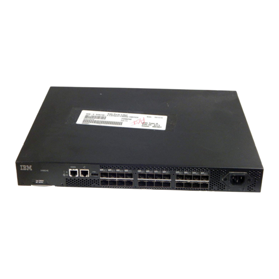
Description System status (top) and power (bottom) LEDs System RS232 console port (RJ-45) Ethernet Port with two Ethernet status LEDs USB port Fibre Channel status LEDs Fibre Channel Ports (24) AC power receptacle SAN24B-4 Express Installation, Service, and User Guide... -
Page 29: Nonport Side Of The Switch
The additional ports are ready to be unlocked in the switch firmware. The license might be part of the licensed paper pack supplied with switch software, or you can purchase the license separately from IBM, who will provide you with a key to unlock it. -
Page 30: Supported Optional Features
In addition, customers can order a set of optional features bundled into one orderable feature, the B24 Enterprise Package. This bundled feature consists of one of each of Fabric Watch, Trunking Activation, Advanced Performance Monitor, Adaptive Networking, and two 8-Port Activations. SAN24B-4 Express Installation, Service, and User Guide... - Page 31 For more information on the use of these features, refer to the Fabric OS Administrator’s Guide. Chapter 1. Introducing the SAN24B-4 Express switch...
- Page 32 SAN24B-4 Express Installation, Service, and User Guide...
-
Page 33: Chapter 2. Installing And Configuring The Switch
SAN24B-4 to operate as a switch. Access Gateway mode and switch mode are mutually exclusive. If you want to use the SAN24B-4 as a switch at a later time, you will need to disable Access Gateway mode and enable switch mode. Changing between Access Gateway and Switch modes is a data disruptive operation. -
Page 34: Installation And Safety Considerations
A minimum of 680 l/min (24 cubic ft/min) of air flow is available to the air intake vents on the nonport side of the switch. v The ambient air temperature does not exceed 40° C (104° F) while the switch is operating. SAN24B-4 Express Installation, Service, and User Guide... -
Page 35: Cabinet Considerations
Cabinet considerations Attention: See “Rack safety” on page xxi for danger and caution notices related to product installations in racks or cabinets. For successful installation and operation of the switch in a cabinet, ensure that the following cabinet requirements are met: v The cabinet must be a standard EIA cabinet. -
Page 36: Time Required
Figure 3 on page 11 shows the rack assembly. The number keys, such as 1 , refer to the items listed in Table 3 on page 11. SAN24B-4 Express Installation, Service, and User Guide... -
Page 37: Rack Assembly
Outer Slide EIA Rack Rail Inner Slide Detail A Front of Switch Detail A SJ000153 Figure 3. Rack assembly 1. Unpack the rack-mount kit and verify that all ordered items and parts are present and undamaged. See Table 3 for a list of parts and the quantities supplied. - Page 38 (away from the ports) as shown in Figure 5 on page 13. b. Attach the inner rail by using three of the 8-32 x 3/16 in. zinc screws ( 6 in Table 3 on page 11). SAN24B-4 Express Installation, Service, and User Guide...
-
Page 39: Mounting The Moving Portion Of The Slide And Mounting Brackets To The Switch
Front SJ000047 Figure 5. Mounting the moving portion of the slide and mounting brackets to the switch c. Repeat step 3a on page 12 and step 3b on page 12 for the second inner rail on the other side of the switch chassis. 4. -
Page 40: Mounting The Fixed Portion Of The Rail And The Locking Brackets To The Rack
Position the switch in front of the rack. Insert the switch into the rack by sliding the inner slides that are mounted on the switch into the outer slides that are mounted on the rack. See Figure 7 on page 15. SAN24B-4 Express Installation, Service, and User Guide... -
Page 41: Recommendations For Cable Management
SJ000049 Figure 7. Inserting slides into the rack rails b. Check the alignment of the slides by sliding the switch in and out of the rack. Any difficulty moving the switch indicates lateral stress or misalignment. If this situation occurs, adjust the slide positions until the movement is smooth. -
Page 42: Configuring The Switch
EZSwitchSetup to complete the basic configuration. See the EZSwitchSetup CD included with the accessory kit for more information. You can also use the SAN24B-4 Quick Start Guide. If you do not want to use EZSwitch Setup, use the instructions in following sections. -
Page 43: Creating A Serial Connection
2. After POST is complete, verify that the switch power and status LEDs on the left of the port side of the switch are green. Creating a serial connection You will perform all basic configuration tasks in this guide using a serial connection. -
Page 44: Setting The Date And Time
Display all of the time zones supported in the firmware v Set the time zone based on a country and city combination or based on a time zone ID such as PST SAN24B-4 Express Installation, Service, and User Guide... -
Page 45: Synchronizing Local Time Using Ntp
The time zone setting has the following characteristics: v You can view the time zone settings. However, only those with administrative permissions can set the time zones. v The tsTimeZone setting automatically adjusts for Daylight Savings Time. v Changing the time zone on a switch updates the local time zone setup and is reflected in local time calculations. - Page 46 "10.32.170.1;10.32.170.2;ntp.localdomain.net" Updating Clock Server configuration...done. Updated with the NTP servers Changes to the clock server value on the principal or primary FCS switch are propagated to all switches in the fabric. SAN24B-4 Express Installation, Service, and User Guide...
-
Page 47: Chapter 3. Operating The Switch
The SAN24B-4 does not have an AC power switch. To power on the SAN24B-4, connect the power cable to the AC receptacle on the switch and to a power source. -
Page 48: Led Locations
Item LED names and descriptions System status LED (green/amber) System power LED (green) Ethernet link status LED Ethernet link speed LED Port status LED for port 3 Port status LED for port 7 SAN24B-4 Express Installation, Service, and User Guide... -
Page 49: Led Patterns
LED patterns Table 4 through Table 7 on page 25 summarize the switch LED locations, color, and meaning, as well as any recommended user response. Power status LED patterns The power status LED patterns are shown in Table 4 Table 4. Power status LED patterns, status, and recommended actions Recommended LED name LED color... -
Page 50: Port Led Patterns During Normal Operation
Check the Port Status (on 1/4 second, off LEDs, error log, SFP, 1/4 second) and cable or loopback plug. Clear the error log. Rerun the diagnostics to verify that the error condition is fixed. SAN24B-4 Express Installation, Service, and User Guide... -
Page 51: Post And Boot Specifications
Ethernet LED patterns Each Ethernet port has two LEDs, which are described in Table 7 Table 7. Ethernet LED patterns Recommended LED name LED color Status of hardware action Ethernet speed LED No light Port speed is 10 No action is required. (right) Mb/sec. -
Page 52: Interpreting Post Results
Attention: Use only transceivers that are supported for this product. Only transceivers purchased from IBM are supported. The use of transceivers that are not supported may cause data loss or cause the product to malfunction. For a listing of transceivers compatible with this product: v Go to the IBM Support Portal www.ibm.com/supportportal. - Page 53 Ensure that cables are properly seated within the connector. Kits are commercially available for cleaning and inspecting these connections. IBM also offers services that will ensure optimal condition of the network. Follow these instructions to install an SFP: 1.
-
Page 54: Sfp Installation And Bail Closing
Figure 9. SFP installation and bail closing Item Description Switch chassis SFP with open bale Closed bale SAN24B-4 Express Installation, Service, and User Guide... -
Page 55: Removing An Sfp
Non-bailed SFPs can be damaged by the removal process and are not recommended. Refer to the interoperability matrix at the following website: www.ibm.com/servers/storage/support/san for a list of supported SFPs and devices. 5. Repeat this procedure for the remaining ports, as required. - Page 56 RANDOM: 0x25, 0x7f, 0x6e, 0x9a, ..9. If the test indicates that all ports are good, the problem is associated with either the cable or SFP. 10. Replace the SFP with an SFP known to be good. SAN24B-4 Express Installation, Service, and User Guide...
-
Page 57: Diagnostic Tests
11. Simulate the data transmission scenario when the error occurred. If the error does not reappear, the original SFP was defective, and should be discarded. If the error does reappear, the cable is defective. Replace the cable and discard the original cable. 12. - Page 58 Note: To achieve in-band support for IP over Fibre Channel, the software must be run on both the HBA and the switch, and it must be supported by both the HBA and HBA driver. SAN24B-4 Express Installation, Service, and User Guide...
-
Page 59: Appendix A. Product Specifications
Note: The -10° to 40° Celsius range applies to the ambient air temperature at the air intake vents on the nonport side of the switch. The temperature inside the switch can be up to 80° Celsius during switch operation. If the internal © Copyright IBM Corp. 2008, 2013... -
Page 60: Facility Requirements
Additional weight of switch not to exceed the cabinet’s weight limits v Cabinet secured to ensure stability in case of unexpected movement, such as an earthquake SAN24B-4 Express Installation, Service, and User Guide... -
Page 61: System Specifications
Descriptions Autoconfiguring port types F_Port, FL_Port, M_Port, N_Port, and E_Port System architecture Nonblocking shared-memory switch System processor IBM PowerPC 440EPx, 667 MHz SDRAM 512 MB DDR2 SDRAM onboard memory operating at 133 MHz Compact flash 1 GB ANSI Fibre Channel protocol... -
Page 62: Data Transmission Ranges
The power supply is not removable. Table 15 lists the power supply specifications for the switch. Table 15. Switch power supply specifications Specification Value Inlet Maximum output from the power supply 75 watts SAN24B-4 Express Installation, Service, and User Guide... -
Page 63: Supported Sfps And Hbas
SFPs for the base configuration. Use only SFPs that are tested and supported. For the most up to date list of supported SFPs and HBAs for the switch, refer to the product interoperability matrix at the IBM SAN Support web pages at: www.ibm.com/servers/storage/support/san... - Page 64 SAN24B-4 Express Installation, Service, and User Guide...
-
Page 65: Appendix B. Link Troubleshooting
Appendix B. Link troubleshooting IBM SAN b-type directors and switches use the latest high bandwidth Fibre Channel technology and auto-negotiate to 16 Gbps, 8 Gbps, 4 Gbps, or 2 Gbps based on the link data rate capability of the attached transceiver and the speed supported by the switches and directors. -
Page 66: Dust, Dirt, Or Other Contaminants
Inspect loss ratings of all cabling components during the selection process. v Record loss measurements for horizontal and vertical cable runs during installation. SAN24B-4 Express Installation, Service, and User Guide... -
Page 67: Attenuation On Lwl Connections
LWL transceivers or use of 8 Gbps LWL transceivers that employ rate select. 2G LWL SFP maximum receive power The IBM SAN b-type 8 Gbps and 16 Gbps directors and switches use the latest high bandwidth Fibre Channel technology and auto-negotiate to 16 Gbps, 8 Gbps, 4 Gbps, or 2 Gbps based on the link data rate capability of the attached transceiver. - Page 68 2 Gbps 10 km SFP -3 dB Optoway SPS-9110AFG 2 Gbps 10 km SFP -3 dB JDSU JSH-21L3AR3 2 Gbps 10 km SFP 1 dB ES212-LP3TA 2 Gbps 10 km SFP -3 dB SAN24B-4 Express Installation, Service, and User Guide...
-
Page 69: Notices
Consult your local IBM representative for information on the products and services currently available in your area. Any reference to an IBM product, program, or service is not intended to state or imply that only that IBM product, program, or service may be used. Any functionally equivalent product, program, or service that does not infringe on any IBM intellectual property right may be used instead. - Page 70 Information concerning non-IBM products was obtained from the suppliers of those products, their published announcements or other publicly available sources. IBM has not tested those products and cannot confirm the accuracy of performance, compatibility or any other claims related to non-IBM products.
-
Page 71: Trademarks
International Business Machines Corporation in the United States, other countries, or both. A complete and current list of other IBM trademarks is available on the Web at http://www.ibm.com/legal/copytrade.shtml Adobe, the Adobe logo, PostScript, and the PostScript logo are either registered trademarks or trademarks of Adobe Systems Incorporated in the United States, and/or other countries. -
Page 72: Electronic Emission Notices
Properly shielded and grounded cables and connectors must be used in order to meet FCC emission limits. IBM is not responsible for any radio or television interference caused by using other than recommended cables and connectors or by unauthorized changes or modifications to this equipment. -
Page 73: Germany Electromagnetic Compatibility Directive
Klasse A ein. Um dieses sicherzustellen, sind die Geräte wie in den Handbüchern beschrieben zu installieren und zu betreiben. Des Weiteren dürfen auch nur von der IBM empfohlene Kabel angeschlossen werden. IBM übernimmt keine Verantwortung für die Einhaltung der Schutzanforderungen, wenn das Produkt ohne Zustimmung der IBM verändert bzw. -
Page 74: People's Republic Of China Class A Electronic Emission Statement
Korea Communications Commission (KCC) Statement Please note that this equipment has obtained EMC registration for commercial use. In the event that it has been mistakenly sold or purchased, please exchange it for equipment certified for home use. SAN24B-4 Express Installation, Service, and User Guide... -
Page 75: Russia Electromagnetic Interference (Emi) Class A Statement
Russia Electromagnetic Interference (EMI) Class A Statement Australia and New Zealand Class A Statement Attention: This is a Class A product. In a domestic environment this product might cause radio interference in which case the user might be required to take adequate measures. - Page 76 SAN24B-4 Express Installation, Service, and User Guide...
-
Page 77: Index
9 Ethernet port 1 creating a serial connection 17 EZSwitchSetup wizard 1 trunking groups 3 Inter-Switch-Link trunking 1 items included 7 LEDs 1 NPIV access gateway 1 optional 4 RJ45 Ethernet management port 1 © Copyright IBM Corp. 2008, 2013... - Page 78 37 notices supported types 26 qualified attention xx testing 30 SFPs 26 caution xvii shock danger xv requirements 33 environmental xiv, xxiii SNMP general 43 management 31 IBM 43 SAN24B-4 Express Installation, Service, and User Guide...
- Page 79 specifications tests boot 25 diagnostic 31 data transmission ranges 36 thermal Fibre Channel ports 36 requirements 34 general 35 time memory 35 setting 18 physical dimensions 33 time zones POST 25 setting 18 power supply 36 trademarks 45 product 33 trunking groups serial port 36 ISL 3...
- Page 80 SAN24B-4 Express Installation, Service, and User Guide...
- Page 82 Part Number: 98Y5367 Printed in USA GA32-0580-03...
Need help?
Do you have a question about the SAN24B-4 and is the answer not in the manual?
Questions and answers