
Subscribe to Our Youtube Channel
Related Manuals for IBM Storage Networking SAN128B-6


Summary of Contents for IBM Storage Networking SAN128B-6
- Page 1 IBM Storage Networking SAN128B-6 MTM Service information: 8960-F96, 8960-N96 Installation, Service, and User Guide SC27-9251-00...
- Page 2 Before you use the information in this publication, be sure to read the general information under “Notices” on page 89. Copyright Portions Copyright © 2018 Broadcom Limited and/or its subsidiaries. All Rights Reserved. © Copyright IBM Corporation 2018. US Government Users Restricted Rights – Use, duplication or disclosure restricted by GSA ADP Schedule Contract with IBM Corp.
-
Page 3: Table Of Contents
. 35 Product documents . xix Brocade documents . xix Initial Setup and Verification ..37 IBM and Brocade product matrix . . xix Items required . . 37 Providing power to the device . . 37 Device Overview . - Page 4 . 77 Verifying correct configuration of the fabric. . 78 Power Supply Assemblies ..57 IBM service replacement responsibilities . . 79 Disconnecting the cables . . 79 Precautions specific to the power supply assemblies 58...
-
Page 5: Figures
. 65 Attaching front brackets to a rack . . 30 Removing a fan assembly . . 69 Attaching the rear brackets to a rack . . 31 Inserting a fan assembly . . 70 © Copyright IBM Corp. 2018... - Page 6 SAN128B-6 Installation, Service, and User Guide...
-
Page 7: Tables
Tables Brocade and IBM product and model number SFP+ FC port status LED patterns during matrix . . xx normal operation. . 53 SFP+ ports numbering . QSFP port status LED patterns during normal QSFP ports numbering . operation . - Page 8 viii SAN128B-6 Installation, Service, and User Guide...
-
Page 9: Read This First
Search for the product Machine type or product name. For Fabric OS Release Notes and access to Fabric OS firmware downloads, go to the IBM Support Portal www.ibm.com/supportportal. Search for the product Machine type or product name, and then follow links for Downloads. -
Page 10: How To Send Your Comments
9000 South Rita Road Tucson, Arizona 85744-0001 U.S.A. When you send information to IBM, you grant IBM a nonexclusive right to use or distribute the information in any way it believes appropriate without incurring any obligation to you. SAN128B-6 Installation, Service, and User Guide... -
Page 11: Safety And Environmental Notices
Safety Notices publication that is shipped with this product. The following notices and statements are used in IBM documents. They are listed below in order of increasing severity of potential hazards. Follow the links for more detailed descriptions and examples of the danger, caution, and attention notices in the sections that follow. -
Page 12: Danger Notices
Electrical cautions CAUTION: Before plugging a cable into any port, be sure to discharge the voltage stored on the cable by touching the electrical contacts to ground surface. CAUTION: Static electricity can damage the chassis and other electronic devices. To avoid damage, keep static-sensitive devices in their static-protective packages until you are ready to install them. - Page 13 General dangers DANGER The procedures in this manual are for qualified service personnel. DANGER Be careful not to accidently insert your fingers into the fan tray while removing it from the chassis. The fan may still be spinning at a high speed. Electrical dangers DANGER For safety reasons, the ESD wrist strap should contain a series 1 megaohm resistor.
-
Page 14: Safety Labels
DANGER Batteries used for RTC/NVRAM backup are not located in operator-access areas. There is a risk of explosion if a battery is replaced by an incorrect type. Dispose of used components with batteries according to local ordinance and regulations. Dangers related to equipment weight DANGER Make sure the rack housing the device is adequately secured to prevent it from becoming unstable or falling over. -
Page 15: Attention Notices
DANGER Hazardous voltage present. Voltages present constitute a shock hazard, which can cause severe injury or death. (L004) CAUTION: Hazardous moving parts nearby. (L008) Attention notices An attention notice indicates the possibility of damage to a program, device, or system, or to data. An exclamation point symbol may accompany an attention notice, but is not required. -
Page 16: Esd Precautions
ESD precautions Attention: Many of the field replaceable units (FRUs) are sensitive to electrostatic discharge (ESD), and can potentially be damaged by improper handling. When working with any FRU, use correct ESD precautions: v Attach ground to the indicated area on the chassis v Wear a wrist grounding strap connected to chassis ground (if the switch is plugged in) or a bench ground. - Page 17 CAUTION: v Do not install a unit in a rack where the internal rack ambient temperatures will exceed the manufacturer’s recommended ambient temperature for all your rack-mounted devices. v Do not install a unit in a rack where the air flow is compromised. Ensure that air flow is not blocked or reduced on any side, front, or back of a unit used for air flow through the unit.
-
Page 18: Rack Relocation (19" Rack)
(R002) Product recycling and disposal Refer to the IBM Systems Environmental Notices and User Guide (Z125-5823) for translated environmental statements and information regarding product recycling and disposal. This document may be provided either in printed version or on the product documentation CD. A more current version may be available through this link ftp://public.dhe.ibm.com/systems/support/warranty/envnotices/... -
Page 19: Preface
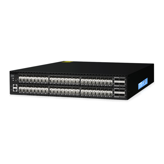
Fibre Channel, and storage area network (SAN) technologies. It describes how to install, service, and use the IBM Storage Networking SAN128B-6 (machine type-models 8960-F96 and 8960-N96 Switch). Throughout this document, the product is referred to as the SAN128B-6, or simply the switch. -
Page 20: Brocade And Ibm Product And Model Number Matrix
Brocade products. Table 1 provides a product matrix to correlate the Brocade products and models to the IBM product names and machine types and model numbers. Products withdrawn from marketing are not listed. -
Page 21: Device Overview
Device Overview The IBM SAN128B-6 offers the following features and capabilities: v Up to 96 auto-sensing ports supporting high-performance 32-Gbps SFP+ ports technology in a single domain with NVMe support on egress-only. v Up to eight auto-sensing 128-Gbps (4 x 32-Gbps) QSFP ports to connect to the QSFP ports of other devices or F_Ports. -
Page 22: License Options
v One green LED to indicate valid system power. v One bicolor (green/amber) LED to indicate the system status. v Two Ethernet LEDs: one bicolor (green/amber) LED to indicate link at 1000/100/10 Mbps and one green LED to indicate activity. v SEEPROM for switch identification. -
Page 23: Nonport-Side View
12. QSFP port 4 ( FC ports 112 - 113 - 114 - 115 ) 13. 48 SFP+ 32-Gbps FC ports 14. 10/100/1000 Mbps RJ-45 Ethernet management port 15. UART RJ-45 serial console port Table 2. SFP+ ports numbering 10 11 16 17 18 19 24 25 26 27 32 33 34 35 40 41 42 43 12 13 14 15... -
Page 24: Device Management Options
Fabric OS MIB Reference connection Management Server Ethernet or serial Fabric OS Administration Guide connection Fabric OS Command Reference IBM Network Advisor (NA) Ethernet or serial IBM Network Advisor documentation set connection NA must be purchased separately. SAN128B-6 Installation, Service, and User Guide... -
Page 25: Preparing For The Installation
Ensure that the airflow direction of the power supply unit matches that of the installed fan tray. The power supplies and fan trays are clearly labeled with either a green arrow with an "E", or an orange arrow with an "I." © Copyright IBM Corp. 2018... -
Page 26: Esd Precautions
CAUTION: Never leave tools inside the chassis. CAUTION: To protect the serial port from damage, keep the cover on the port when not in use. CAUTION: If you do not install a module or a power supply in a slot, you must keep the slot filler panel in place. -
Page 27: Power Precautions
Power precautions DANGER Make sure that the power source circuits are properly grounded, then use the power cord supplied with the device to connect it to the power source. DANGER If the installation requires a different power cord than the one supplied with the device, make sure you use a power cord displaying the mark of the safety agency that defines the regulations for power cords in your country. -
Page 28: Lifting And Weight-Related Precautions
CAUTION: Use a separate branch circuit for each power cord, which provides redundancy in case one of the circuits fails. CAUTION: Ensure that the device does not overload the power circuits, wiring, and over-current protection. To determine the possibility of overloading the supply circuits, add the ampere (amp) ratings of all devices installed on the same circuit as the device. -
Page 29: Laser Precautions
All fiber-optic interfaces use Class 1 lasers. DANGER Use only optical transceivers that are qualified by IBM and comply with the FDA Class 1 radiation performance requirements defined in 21 CFR Subchapter I, and with IEC 60825 and EN60825. Optical products that do not comply with these standards might emit light that is hazardous to the eyes. -
Page 30: Quick Installation Checklist
Quick installation checklist This checklist provides a high-level overview of the basic installation process from the planning stage to the point where the device comes online and is ready to be deployed. Completing all the tasks in the suggested order ensures successful installation. Brocade recommends that you print this checklist and take it to the installation site. -
Page 31: Installation And Basic System Configuration
Table 7. Installation and basic system configuration Task Task details or additional information Completed Mount the device. Choose one of the following mounting options: v Mount the device as a standalone unit. Refer to“Standalone installation” on page 14. v Mount the device in a four-post rack. Refer to“Installing the Universal Four-Post Rack Kit”... -
Page 32: Shipping Carton Contents
Table 7. Installation and basic system configuration (continued) Task Task details or additional information Completed Verify that the device operates v Check the LEDs to verify operation of functional parts. Refer correctly. to“Port-side LED locations” on page 51 and“Nonport-side LED locations”... -
Page 33: Mounting The Switch
To prevent damage to the chassis and components, never attempt to lift the chassis using the fan or power supply handles. These handles were not designed to support the weight of the chassis. 18-32 kg (39.7-70.5 lbs) © Copyright IBM Corp. 2018... -
Page 34: Standalone Installation
Standalone installation About this task Complete the following steps to install the device as a standalone unit on a table. Procedure 1. Unpack the device and verify the items listed under “Shipping carton contents” on page 12 are present and undamaged. 2. -
Page 35: Time And Items Required
v Two people are required to install the device in a rack. One person holds the device, while the other screws in the front and rear brackets. v Before mounting your device, review any specific installation and facility requirements in this Hardware Installation Guide. -
Page 36: Rack Kit Parts
Figure 3. Rack kit parts 1. Front brackets (2) 2. Extension brackets, medium (2) 3. Rear brackets, short (2) 4. Rear brackets, long (2) 5. Extension brackets, long (2) 6. Screw, 8-32 x 5/16-in., panhead Phillips (8) 7. Screw, 8-32 x 5/16-in., flathead Phillips (16) 8. -
Page 37: Flush-Front Mounting
Flush-front mounting CAUTION: The device must be turned off and disconnected from the fabric during this procedure. Note: The illustrations in the rack installation procedures are for reference only and may not show the device that you are installing. Complete the following tasks to install the device in a four-post rack. 1. -
Page 38: Attaching The Bracket Extensions To The Device
3. Screws, 8-32 x 5/16-in., flathead Phillips Attaching the bracket extensions to the device About this task Complete the following steps to attach the extension brackets to the device. There are medium and long extension brackets that you can use for this step. Procedure 1. -
Page 39: Attaching The Rear Brackets To The Extensions
3. Attach the left front bracket to the left front rack post using two 10-32 x 5/8-in. panhead screws and two retainer nuts. Use the upper and lower holes in the bracket. 4. Tighten all the 10-32 x 5/8-in. screws to a torque of 25 in-lb (29 cm-kg). Figure 6. -
Page 40: Attaching The Rear Brackets To The Rack Posts
Figure 7. Attaching the rear brackets to the extensions 1. Rear brackets 2. Screws, 6-32 x 1/4-in., panhead Phillips Attaching the rear brackets to the rack posts About this task Complete the following steps to attach the rear brackets to the rack posts. Procedure 1. -
Page 41: Flush-Rear (Recessed) Mounting
Figure 8. Attaching the rear brackets to the rack posts 1. Screws, 10-32 x 5/8-in., panhead Phillips 2. Retainer nuts, 10-32 Flush-rear (recessed) mounting The flush-rear (recessed) mounting is similar to the flush-front mounting except that the brackets are reversed on the device. CAUTION: The device must be turned off and disconnected from the fabric during this procedure. -
Page 42: Attaching The Bracket Extensions To The Front Of The Device
Procedure 1. Position the right front bracket with the flat side against the right rear side of the device, as shown in Figure 9. 2. Insert four 8-32 x 5/16-in. flathead screws through the vertically aligned holes in the bracket and then into the holes on the side of the device. -
Page 43: Installing The Device In The Rack
Figure 10. Attaching the bracket extensions to the device 1. Extension brackets 2. Screws, 8-32 x 5/16-in., flathead Phillips Installing the device in the rack About this task Complete the following steps to install the device in the rack. Procedure 1. -
Page 44: Attaching The Rear Brackets To The Extensions At The Front Of The Device
Figure 11. Positioning the device in the rack Screws, 10-32 x 5/8-in., panhead Phillips Retainer nuts, 10-32 Attaching the rear brackets to the extensions at the front of the device About this task Complete the following steps to attach the rear brackets to the extensions. There are short and long front brackets that you can use for this step. -
Page 45: Attaching The Short Or Long Rear Brackets To The Extensions
Figure 12. Attaching the rear brackets to the extensions at the front of the device 1. Rear brackets, short 2. Screws, 6-32 x 1/4-in., panhead Phillips Figure 13. Attaching the short or long rear brackets to the extensions 1. Rear bracket, short or long 2. -
Page 46: Attaching The Rear Brackets To The Front Rack Posts
Attaching the rear brackets to the front rack posts About this task Complete the following steps to attach the rear brackets to the front rack posts. Procedure 1. Attach the right rear bracket to the right front rack post using two 10-32 x 5/8-in. screws and two retainer nuts, as shown in Figure 14. -
Page 47: Time And Items Required
v Hardware devices illustrated in these procedures are only for reference and may not depict the device you are installing into the rack. Time and items required Allow 15 to 30 minutes to complete the installation. The following items are required to install the device using the Universal Two-Post Rack Kit: v #2 Phillips torque screwdriver v 1/4-inch slotted-blade torque screwdriver Parts list... -
Page 48: Flush-Front Mounting
Flush-front mounting Observe the following notes when using this procedure: v The device must be turned off and disconnected from the fabric during this procedure. v The illustrations in this document show a 1U device, but the instructions are the same for a 2U device. v The illustrations for this procedure show a two-post rack with narrow posts (3- to 5-inch) as an example. -
Page 49: Attaching The Front Brackets To The Rack
Figure 16. Attaching the front brackets 1. The SAN128B-6 device 2. Front brackets, right and left 3. Screws, 8-32 x 5/16-in., flathead Phillips Attaching the front brackets to the rack About this task Complete the following steps to install the device in the rack. Procedure 1. -
Page 50: Attaching The Rear Brackets To The Rack
Figure 17. Attaching front brackets to a rack 1. Screws, 10-32 x 5/8-in., panhead Phillips 2. Retainer nuts, 10-32 Attaching the rear brackets to the rack About this task Complete the following steps to attach the rear brackets to the rack. Procedure 1. -
Page 51: Attaching The Rear Brackets To The Device
Figure 18. Attaching the rear brackets to a rack 1. Retainer nuts, 10-32 2. Rear brackets 3. Screws, 10-32 x 5/8-in., panhead Phillips Attaching the rear brackets to the device About this task Complete the following steps to attach the rear brackets to the device. Procedure 1. -
Page 52: Mid-Mounting
Figure 19. Attaching the rear brackets to the device 1. Screws, 8-32 x 5/16-in., panhead Phillips Mid-mounting Observe the following notes when using this procedure: v The device must be turned off and disconnected from the fabric during this procedure. v The illustrations in this document show a 1U device, but the instructions are the same for a 2U device. -
Page 53: Attaching The Front Brackets To The Rack
Figure 20. Attaching the front brackets 1. The SAN128B-6 device 2. Front brackets, right and left 3. Screws, 8-32 x 5/16-in., flathead Phillips Attaching the front brackets to the rack About this task Complete the following steps to install the device in the rack. Procedure 1. -
Page 54: Attaching The Rear Brackets To The Rack
Figure 21. Attaching front brackets to a rack 1. Screws, 10-32 x 5/8-in., panhead Phillips 2. Retainer nuts, 10-32 Attaching the rear brackets to the rack About this task Complete the following steps to attach the rear brackets to the rack. Procedure 1. -
Page 55: Attaching The Rear Brackets To The Device
Figure 22. Attaching the rear brackets to a rack 1. Retainer nuts, 10-32 2. Rear brackets (right and left) 3. Screws, 10-32 x 5/8-in., panhead Phillips Attaching the rear brackets to the device About this task Complete the following steps to attach the rear brackets to the device. Procedure 1. -
Page 56: Attaching The Rear Brackets To The Device
Figure 23. Attaching the rear brackets to the device 1. Screws, 8-32 x 5/16-in., panhead Phillips SAN128B-6 Installation, Service, and User Guide... -
Page 57: Initial Setup And Verification
POST, BOOT, and diagnostics tests, refer to “Monitoring the device” on page 51. Establishing a first-time serial connection About this task Perform the following steps to log in to the device through the serial connection. © Copyright IBM Corp. 2018... -
Page 58: Configuring The Ip Address
Procedure 1. Connect the serial cable to the serial port on the device and to an RS-232 serial port on the workstation. If the serial port on the workstation is RJ-45 instead of RS-232, remove the adapter on the end of the serial cable and insert the exposed RJ-45 connector into the RJ-45 serial port on the workstation. -
Page 59: Using Dhcp To Set The Ip Address
Using DHCP to set the IP address When using DHCP, the switch obtains its IP address, subnet mask, and default gateway address from the DHCP server. The DHCP client can only connect to a DHCP server that is on the same subnet as the switch. -
Page 60: Setting The Time Zone
v yy: Specifies the year, valid values are 00 to 37 and 70 to 99. Year values from 70 to 99 are interpreted as 1970 to 1999; year values from 00 to 37 are interpreted as 2000 to 2037. device:admin> date Thu Dec 22 14:05:10 UTC 2016 device:admin>... -
Page 61: Customizing The Chassis Name And Switch Name
The ipaddr variable represents the IP address of the NTP server that the device can access. This argument is optional; by default, the value is "LOCL". switch:admin> tsclockserver 192.168.126.60 Updating Clock Server configuration...done. Updated with the NTP servers Customizing the chassis name and switch name About this task Changing the chassis and switch names is important for distinguishing and identifying the device uniquely and for accurate tracking of logs and errors. -
Page 62: Verifying Correct Operation
domain ID is already in use, the fabric segments. To find the domain IDs that are currently in use, enter the fabricShow command on another switch in the fabric. Perform the following steps to modify the domain ID. a. Disable the switch by entering the switchDisable command. b. -
Page 63: Backing Up The Configuration
460400 Online FC F-Port 10:00:8c:7c:ff:5c:c5:01 460500 Online FC F-Port 10:00:8c:7c:ff:58:4c:00 460600 Online FC F-Port 10:00:8c:7c:ff:5c:c9:01 460700 Online FC F-Port 10:00:8c:7c:ff:5c:bd:00 460800 No_Module 460900 No_Module 10 10 460a00 No_Module 11 11 460b00 No_Module 12 12 460c00 No_Module 13 13 460d00 No_Module 14 14 460e00 No_Module... - Page 64 Results All devices are returned to their initial state the next time the switch is powered on. SAN128B-6 Installation, Service, and User Guide...
-
Page 65: Installing Transceivers And Cables
Required number of supported transceivers DANGER Use only optical transceivers that are qualified by IBM and comply with the FDA Class 1 radiation performance requirements defined in 21 CFR Subchapter I, and with IEC 60825 and EN60825. Optical products that do not comply with these standards might emit light that is hazardous to the eyes. -
Page 66: Cleaning The Fiber-Optic Connectors
Installing an SFP+ transceiver About this task The device supports only IBM-qualified transceivers. If you use an unqualified transceiver, the switchshow command output shows the port in a Mod_Inv state. Fabric OS also logs the issue in the system error log. To insert an SFP+ transceiver, complete the following steps:... -
Page 67: Replacing An Sfp+ Transceiver
Note: The 16- and 32-Gbps SFP+ transceivers do not have bails. Always use the pull tab to insert or remove the transceivers, as the SFP might be hot. Procedure 1. Use the pull tab on the 16- and 32-Gbps SFP+ transceivers to help push the transceiver into the port. Transceivers are keyed so that they can only be inserted with the correct orientation. -
Page 68: Installing A Qsfp Transceiver
Installing a QSFP transceiver About this task The device supports only IBM-qualified transceivers. If you use an unqualified transceiver, the switchshow command output shows the port in a Mod_Inv state. Fabric OS also logs the issue in the system error log. To insert an QSFP transceiver, complete the following steps: Note: QSFP transceivers have pull tabs rather then bails. -
Page 69: Replacing A Qsfp Transceiver
Procedure 1. Use the pull tab on these transceivers to help push the transceiver into the port. Transceivers are keyed so that they can only be inserted with the correct orientation. If a transceiver does not slide in easily, ensure that it is correctly oriented. Push the correctly oriented transceiver into the port until it is firmly seated and the latching mechanism clicks. -
Page 70: Verifying The Operation Of New Transceivers
transceiver until the latching mechanism clicks. Figure 28. Replacing a QSFP optical transceiver 1. Pull tab 2. QSFP cable 3. QSFP transceiver 4. Position a cable so that the key (the ridge on one side of the cable connector) is aligned with the slot in the transceiver. -
Page 71: Monitoring The Device
8. FC port 96 (QSFP 0) status LED 9. FC port 97 (QSFP 0) status LED 10. FC port 98 (QSFP 0) status LED 11. FC port 99 (QSFP 0) status LED 12. FC port 119 (QSFP 5) status LED © Copyright IBM Corp. 2018... -
Page 72: System Power Led
13. FC port 118 (QSFP 5) status LED 14. FC port 117 (QSFP 5) status LED 15. FC port 116 (QSFP 5) status LED 16. QSFP port 5 17. SFP+ (upper) port 58 18. SFP+ (upper) port 58 status LED 19. -
Page 73: Fc Port Status Led
FC port status LED Refer to the following table to interpret the FC port status LEDs. Table 12. SFP+ FC port status LED patterns during normal operation LED color Status of hardware Recommended action No light Indicates one of the following: v Verify the power LED is on, and v No signal or light carrier (media or check the SFP+ and cable. -
Page 74: Nonport-Side Led Locations
Table 13. QSFP port status LED patterns during normal operation (continued) LED color Status of hardware Recommended action Fast-flashing green (on 1/4 second; Port is online and an internal No action required. then off 1/4 second) loopback diagnostic test is running. Flickering green Port is online and frames are flowing No action required. -
Page 75: Power Supply Ok And Fail Status Leds
Power supply OK and FAIL status LEDs Refer to the following table to interpret the power supply status LEDs during normal operation. Table 14. Power supply status LEDs during normal operation OK LED FAIL LED Description Action required No AC power to all the power supplies. None. -
Page 76: Interpreting The Boot Results
Perform the following steps to determine whether POST completed successfully and whether any errors were detected. Procedure 1. Verify that the LEDs on the device indicate that all components are healthy. If one or more LEDs do not display a healthy state: a. -
Page 77: Power Supply Assemblies
Figure 31. AC power supply assembly 1. Power supply unit FAIL LED 2. Power supply unit handle 3. AC power cable receptacle 4. Power supply assembly latch 5. Power supply unit OK LED © Copyright IBM Corp. 2018... -
Page 78: Precautions Specific To The Power Supply Assemblies
Note: The two power supply assemblies concurrently installed in the chassis must be of the same power type, model (airflow direction), and part number. If the airflow directions are different, an error is generated on the console. Note: The power supply assembly units are hot-swappable if they are replaced one at a time. They are identical and fit into either slot. -
Page 79: Power Supply Ok And Fail Status Leds
v Intake power supply and fan assembly with an orange "I" label or without any label: Pulls air from the nonport-side of the switch and exhausts it out the port side. v Nonport-side air intake v Port-side air exhaust v Back-to-front (nonport-side to port-side) airflow v Part numbers ending with -R v Exhaust power supply and fan assembly with a green "E"... -
Page 80: Time And Items Required
Installing an additional power supply and fan assembly (hot-install) If your device is up and running with a single power supply assembly and you want to install an additional power supply, complete the following steps. 1. Insert the new power supply assembly. 2. -
Page 81: Removing A Power Supply And Fan Assembly
v tempshow v sensorshow Refer to theFabric OS Command Reference for output examples and descriptions. Removing a power supply and fan assembly About this task Complete the following steps to remove a faulty power supply and fan assembly. CAUTION: The power supply switch must be in the off position when you insert the power supply into the chassis. -
Page 82: Inserting A New Power Supply Assembly
Inserting a new power supply assembly Before you begin The new power supply assembly must have the same part number and airflow label (or lack thereof) as the power supply assembly already installed. About this task Complete the following steps to insert a new power supply assembly into the chassis. CAUTION: The power supply switch must be in the off position when you insert the power supply into the chassis. -
Page 83: Verifying The Operation Of The Power Supply And Fan Assemblies
3. Gently push the power supply assembly into the chassis until it is firmly seated. 4. Plug the power cord into the power supply assembly and power is provided to the device immediately. 5. Verify that the LED on the new power supply assembly displays a steady green light while the device is operating. - Page 84 SAN128B-6 Installation, Service, and User Guide...
-
Page 85: Fan Assemblies
(airflow direction), and part number. If the airflow directions are different, an error is generated on the console. Note: The fan assembly units are hot-swappable if they are replaced one at a time. They are identical and fit into any fan slot. © Copyright IBM Corp. 2018... -
Page 86: Precautions Specific To The Fan Assemblies
Note: The device can operate all the ports with two fan assemblies if you do not require redundancy. The device fans are fixed inside the fan assemblies to provide necessary airflow to cool the whole system. There are two fans located in each unit. The system software sets fan speed and measures fan speed through the tachometer interface. -
Page 87: Fan Assembly Status Led
v Nonport-side air exhaust v Port-side air intake v Front-to-back (port-side to nonport-side) airflow v Part numbers ending with -F Fan assembly status LED Refer to the following table to interpret the fan assembly status LED during normal operation Table 17. Fan assembly status LED patterns during normal operation LED color Description Action required... -
Page 88: Time And Items Required
Replacing a fan assembly (hot-swap) If your device is up and running with three fan assemblies, but one of them has failed, complete the following steps. 1. Remove the old or failed fan assembly. 2. Insert the new fan assembly. 3. -
Page 89: Inserting A New Fan Assembly
steady green LED. Figure 35. Removing a fan assembly 1. The SAN128B-6 device 2. Fan assembly slot 1 3. Fan assembly unit 4. Fan assembly handle 2. Using a Phillips screwdriver, unscrew the captive screw. 3. Remove the power supply and fan assembly from the chassis by pulling the handle out and away from the chassis. -
Page 90: Verifying The Operation Of The Power Supply And Fan Assemblies
Figure 36. Inserting a fan assembly 1. The SAN128B-6 device 2. Fan assembly slot 1 3. Fan assembly unit 4. Fan assembly handle 4. Gently push the fan assembly into the chassis until it is firmly seated. 5. Using the Phillips screwdriver, secure the fan assembly to the chassis by tightening the captive screw. 6. -
Page 91: Chassis Replacement
Before replacing the chassis, verify that the replacement is necessary. Ensure that the components are firmly seated when troubleshooting. Contact IBM support if you have any questions about whether the chassis should be replaced. Any of the following events might indicate that the chassis requires replacement: v One or more components do not function properly. -
Page 92: Preparing For Replacement
information for these components before disconnecting the chassis from the network, fabric, and power to begin removal procedures. After you reinstall components in the new chassis, follow exact procedures to reconnect to the network, fabric and power, and then download firmware if necessary and verify system operation and configuration. -
Page 93: Critical Information Checklist
Procedure 1. Run supportShow, which includes most of the information in the following table and more. Be sure to record the location of the .txt files that you create in this procedure that are not called out in the supportShow results. For detailed information about Fabric OS commands, refer to the Fabric OS Command Reference. - Page 94 Path/Filename [<home dir>/config.txt]: config-switch0.txt Section (all|chassis|switch [all]): all Password: Upload complete switch: admin> 4. Record the WWN value: Enter wwn, and then copy the command output into a file named config-miscinfo.txt. switch:admin> wwn 10:00:00:60:69:00:00:0a 5. Enter ipAddrShow, and then copy the command output into the config-miscinfo.txt file. switch:admin>...
-
Page 95: Powering Down The Switch
switch:admin> licenseshow S9bddb9SQbTAceeC: Fabric license eezeRRySff0fSe: Remote Switch license bzbzRcbcSc0c0SY: Remote Fabric license dSeR9RcSeeTfSAq: Extended Fabric license RyeSzRScycTzfT09: Entry Fabric license RyeSzRScycazfT0G: Trunking license RyeSzRScycS0fT09: 4 Domain Fabric license 9. Enter supportShow; then copy the command output into a text file named "spptshow.txt." Note: The supportShow command has a very long output and time for completion. -
Page 96: Downloading The Configuration
c. Repeat step a and step b for the remaining ports. d. Organize the cables as required. Note: Do not route cables in front of the air exhaust vents. What to do next Allow the customer to “Downloading the configuration” and “Verifying correct operation of system” on page 77 and then proceed with “Reconnecting system to the network and fabric”... -
Page 97: Verifying Correct Operation Of System
Verifying correct operation of system About this task Complete the following steps to verify the correct operation of the device. Procedure 1. Log in to the device as admin. switch:admin> login login: admin password: xxxxxxxx switch:admin> 2. Enter the chassisShow command to verify that airflow direction set on WWN cards matches airflow direction for fans in fan and power supply assemblies installed in device. -
Page 98: Verifying Correct Configuration Of The Fabric
4. Verify that all the IP address information is correct by entering ipAddrShow and checking the results against the IP information recorded in the config-miscinfo.txt file. switch:admin> ipaddrshow SWITCH Ethernet IP Address: 14.25.60.14 Ethernet Subnetmask: 255.55.0.0 Gateway IP Address: 14.25.43.1 DHCP: Off Verifying correct configuration of the fabric About this task... -
Page 99: Ibm Service Replacement Responsibilities
If other issues exist, contact your support provider. IBM service replacement responsibilities IBM System Services Representatives (SSR) are responsible for the physical replacement and labeling of the chassis. The SSR performs the following tasks during the replacement: 1. “Disconnecting the cables”... - Page 100 SAN128B-6 Installation, Service, and User Guide...
-
Page 101: Appendix A. Product Specifications
Modes of operation Fibre Channel Class 2 and Class 3 Fabric initialization Complies with FC-SW-3 Rev. 6.6 FCIP (IP over Fibre Complies with FC-IP 2.3 of FCA profile Channel) Port Status Bicolor LED (amber/green) © Copyright IBM Corp. 2018... - Page 102 Other System component Description Serial console port One three-wire (Tx, Rx, Gnd) UART serial port Ethernet management port One 1000/100/10 Mbps Ethernet port USB port One external USB port LEDs System component Description System power LED One green system power status LED (lower) on the port side. System status LED One bicolor (green/amber) system status LED (upper) on the port side.
- Page 103 Environmental requirements Condition Operational Non-operational Ambient temperature 0°C to 40°C (32°F to 104°F) -25°C to 70°C (-13°F to 158°F) Relative humidity 10% to 85% at 40°C (104°F) 10% to 90% non-condensing (non-condensing) Altitude (above sea 0 to 3000 m (9,842 feet) 0 to 12000 m (39,370 feet) level) Shock...
- Page 104 Power consumption (maximum configuration) @200 VAC Minimum number of Model name @100 VAC input input power supplies Notes SAN128B-6 9.5 A 4.55 A 1 (Input current and Fully configured all ports with 100% switch VA are for 1 PSU. traffic rate, fans at high speed, and 958.59 VA 913.13 VA Watts and BTUs/hr...
- Page 105 Transmit data (output from SAN128B-6) Logic ground Logic ground Receive data (input into SAN128B-6) Not supported Not supported Note: These specifications are for the serial connector on IBM platforms only. Serial port specifications (protocol) Parameter Value Baud 9600 Data bits...
- Page 106 Memory specifications Memory Type Size Main Memory DDR4 SDRAM with 8-bit ECC, SODIMM package, 8 GB, 64-bit operating at 1600 MT/s Boot Flash Parallel NOR flash embedded memory 8 MB + 16 MB eUSB Module 2 GB Regulatory compliance (EMC) v FCC Part 15, Subpart B (Class A) v EN 55032/55024 (CE Mark) (Class A) v ICES-003 (Canada)
-
Page 107: Appendix B. Cable Routing Table
If the information is not already available, have the customer use Table 19 to record cable routing information. Table 19. Cable routing table for SAN128B-6 Slot/Port of the Port Cable labels Connected device device Switch end Device end © Copyright IBM Corp. 2018... - Page 108 Table 19. Cable routing table for SAN128B-6 (continued) Slot/Port of the Port Cable labels Connected device device SAN128B-6 Installation, Service, and User Guide...
-
Page 109: Notices
Consult your local IBM representative for information on the products and services currently available in your area. Any reference to an IBM product, program, or service is not intended to state or imply that only that IBM product, program, or service may be used. Any functionally equivalent product, program, or service that does not infringe on any IBM intellectual property right may be used instead. -
Page 110: Trademarks
International Business Machines Corp., registered in many jurisdictions worldwide. Other product and service names might be trademarks of IBM or other companies. A current list of IBM trademarks is available on the web at Copyright and trademark information atwww.ibm.com/legal/copytrade.shtml Adobe, the Adobe logo, PostScript, and the PostScript logo are either registered trademarks or trademarks of Adobe Systems Incorporated in the United States, and/or other countries. -
Page 111: Ce Statement
Cet appareil numérique de la classe A est conforme à la norme NMB-003 du Canada. CE statement Attention: This is a Class A product. In a domestic environment, this product might cause radio interference, and the user might be required to take corrective measures. The standards compliance label on this device contains the CE mark which indicates that this system conforms to the provisions of the following European Council directives, laws, and standards: Electromagnetic Compatibility (EMC) Directive 2014/30/EU... -
Page 112: China Rohs
China ROHS Refer to the latest revision of the China ROHS document (P/N 53 1000428 xx) which ships with the product. FCC warning (US only) This equipment has been tested and complies with the limits for a Class A computing device pursuant to Part 15 of the FCC Rules. -
Page 113: Index
89 trademarks 90 safety Brocade IBM contacts ix notices xi documents xix IBM Publications Center ix, xix rack installation xvi equivalent product models xx IBM Support Portal ix, xix rack relocation xviii BSMI statement (Taiwan) 90 intellectual property 89... - Page 114 SAN128B-6 Installation, Service, and User Guide...
- Page 116 IBM® Part Number: 01JC270 Printed in USA SC27-9251-00...
Need help?
Do you have a question about the Storage Networking SAN128B-6 and is the answer not in the manual?
Questions and answers