Table of Contents
Advertisement
Quick Links
IBM System Storage SAN40B-4
Installation, Service, and User's Guide
Service information: 2498 - B40, 40E
Read Before Using
This product contains software that is licensed under written license agreements. Your use of such software is subject to
the license agreements under which they are provided.
GA32-0581-00
Advertisement
Table of Contents

Related Manuals for IBM SAN40B-4 - System Storage Switch


Summary of Contents for IBM SAN40B-4 - System Storage Switch
- Page 1 IBM System Storage SAN40B-4 Installation, Service, and User’s Guide Service information: 2498 - B40, 40E Read Before Using This product contains software that is licensed under written license agreements. Your use of such software is subject to the license agreements under which they are provided.
- Page 3 IBM System Storage SAN40B-4 Installation, Service, and User’s Guide Service information: 2498 - B40, 40E GA32-0581-00...
- Page 4 © Copyright International Business Machines Corporation 2008. All rights reserved. US Government Users Restricted Rights – Use, duplication or disclosure restricted by GSA ADP Schedule Contract with IBM Corp.
-
Page 5: Table Of Contents
Brocade documents ..... . . xix IBM and Brocade product matrix ....xx Getting help . - Page 6 Chapter 3. Operating the switch ....21 Powering the switch on and off ....21 Interpreting LED activity .
-
Page 7: Figures
13. Captive screws on the power supply fan assemblies ....32 14. Installing a replacement power supply fan assembly ....33 © Copyright IBM Corp. 2008... - Page 8 SAN40B-4 Installation, Service, and User’s Guide...
-
Page 9: Tables
......xii 2. Brocade and IBM product and model number matrix ....xx 3. - Page 10 viii SAN40B-4 Installation, Service, and User’s Guide...
-
Page 11: Safety And Environmental Notices
IDs, which are displayed in parentheses, for example (D004), at the end of each notice. Use this ID to locate the translation of these danger and caution notices in the IBM Systems Safety Notices (G229–9054) publication, which is on the CD-ROM that accompanies this product. - Page 12 DANGER Overloading a branch circuit is potentially a fire hazard and a shock hazard under certain conditions. To avoid these hazards, ensure that your system electrical requirements do not exceed branch circuit protection requirements. Refer to the information that is provided with your device or the power rating label for electrical specifications.
-
Page 13: Caution Notices
Electrical voltage and current from power, telephone, and communication cables are hazardous. To avoid a shock hazard: v Connect power to this unit only with the IBM provided power cord. Do not use the IBM provided power cord for any other product. -
Page 14: Sample Caution Notices
Table 1. Sample caution notices If the symbol is... It means..A hazardous electrical condition with less severity than electrical danger. A generally hazardous condition not represented by other safety symbols. A specification of product weight that requires safe lifting practices. The weight range of the product is listed below the graphic, and the graphic and the wording of the caution varies, depending on the weight... -
Page 15: Safety Labels
Safety labels As an added precaution, safety labels are often installed directly on products or product components to warn of potential hazards. These can be either danger or caution notices, depending upon the level of the hazard. The actual product safety labels may differ from these sample safety labels: DANGER Hazardous voltage, current, or energy levels are present inside any component that has this label attached. -
Page 16: Rack Safety
Rack safety Rack installation DANGER Observe the following precautions when working on or around your IT rack system: v Heavy equipment—personal injury or equipment damage might result if mishandled. v Always lower the leveling pads on the rack cabinet. v Always install stabilizer brackets on the rack cabinet. v To avoid hazardous conditions due to uneven mechanical loading, always install the heaviest devices in the bottom of the rack cabinet. -
Page 17: Rack Relocation (19" Rack)
Rack relocation (19″ rack) CAUTION: Removing components from the upper positions in the rack cabinet improves rack stability during relocation. Follow these general guidelines whenever you relocate a populated rack cabinet within a room or building: v Reduce the weight of the rack cabinet by removing equipment starting at the top of the rack cabinet. -
Page 18: Product Recycling And Disposal
(TI) que reciclen responsablemente sus equipos cuando éstos ya no les sean utiles. IBM dispone de una serie de programas y servicios de devolucion de productos en varios países, a fin de ayudar a los propietarios de equipos a reciclar sus productos de TI. -
Page 19: Battery Return Program
United States, go to http://www.ibm.com/ibm/environment/ products/index.shtml or contact your local waste disposal facility. In the United States, IBM has established a return process for reuse, recycling, or proper disposal of used IBM sealed lead acid, nickel cadmium, nickel metal hydride, and other battery packs from IBM equipment. - Page 20 For proper collection and treatment, contact your local IBM representative. xviii SAN40B-4 Installation, Service, and User’s Guide...
-
Page 21: About This Document
Fibre Channel, and storage area network (SAN) ™ technologies. It describes how to install, service, and use the IBM System Storage SAN40B-4 (2498 Models 40B and E40). Throughout this document, the product is referred to as the SAN40B-4 , or simply the switch to apply to both models. -
Page 22: Ibm And Brocade Product Matrix
When you use any of the Brocade documents, you will notice that the model numbers reflect the original Brocade products. Table 2 provides a product matrix for you to use to correlate the Brocade model numbers to the IBM product names and machine types and model numbers. -
Page 23: How To Send Your Comments
Department GZW 9000 South Rita Road Tucson, Arizona 85744-0001 U.S.A. When you send information to IBM, you grant IBM a nonexclusive right to use or distribute the information in any way it believes appropriate without incurring any obligation to you. - Page 24 xxii SAN40B-4 Installation, Service, and User’s Guide...
-
Page 25: Chapter 1. Introducing The San40B-4 Switch
Chapter 1. Introducing the SAN40B-4 switch The IBM System Storage SAN40B-4 is an enterprise-class 8 Gbps Fibre Channel switch that is designed to handle the large-scale SAN requirements of an enterprise, and can also be used to address the SAN requirements of a small to medium-sized workgroup. -
Page 26: Supported Connectivity
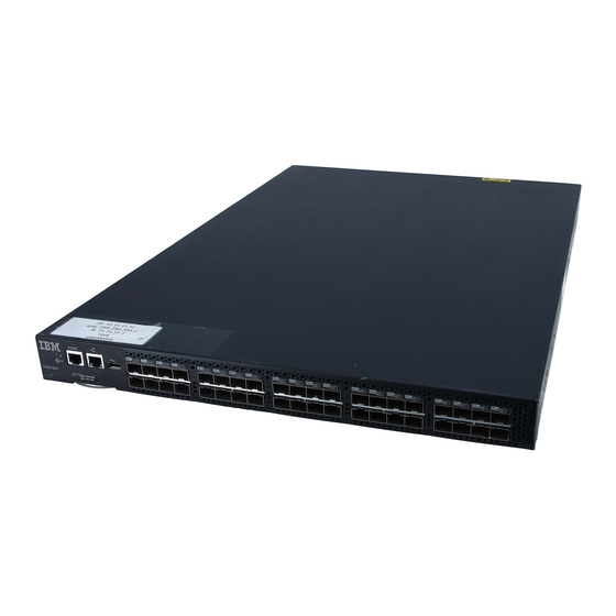
Supported connectivity Specific details on supported operating systems, servers, and devices, storage products attachability, SAN connectivity products, and configuration options can be found in the interoperability matrices at the following web site: www.ibm.com/ servers/storage/support/san. Port side of the switch Figure 1 shows the port side of the switch. The port side of the switch includes the system status LED, console port, Ethernet port and LEDs, USB port, and Fibre Channel ports and the corresponding port status LEDs.. -
Page 27: Port Numbering
Item number Description System RS232 console port (RJ-45) System Ethernet port (RJ-45) Ethernet port LEDs (green/amber) USB port Fibre Channel port status LED Fibre Channel ports (40) Port numbering The Fibre Channel ports on the switch are numbered from left to right, in eight-port groups from 0 to 39 as shown in Figure 2 9 10 11 16 17 18 19... -
Page 28: Nonport Side Of The Switch
The additional ports are ready to be unlocked in the switch firmware. The license might be part of the licensed paper pack supplied with switch software, or you can purchase the license separately from IBM, who will provide you with a key to unlock SAN40B-4 Installation, Service, and User’s Guide... -
Page 29: Isl Trunking Groups
Typically the switch is shipped with a paper pack that specifies the transaction key to use with the Software License Keys link. Use this transaction key at the following Web site: http://www.ibm.com/servers/ storage/support/san. - Page 30 FC Router (FCR) connection when connected to another 8 Gbps capable port v FICON w/ CUP–designed to provide in-band management of the supported SAN b-type switch, router, and supported IBM System z and zSeries servers. To enable in-band management on multiple switches and directors, each switch, router, or director must be configured with the appropriate FICON CUP feature.
-
Page 31: Chapter 2. Installing And Configuring The Switch
– Four rubber feet, required for setting up the switch as a stand-alone unit – SFP transceivers (quantity depending upon features ordered) – IBM System Storage SAN40B-4 Installation, Service, and User’s Guide (this document) – IBM System Storage SAN40B-4 Quick Start Guide –... -
Page 32: Electrical Considerations
The switch can be installed either as a free-standing unit, or installed in an EIA cabinet, using an optional slide-rail rack mount kit. When mounting into a slide-rail rack, you can mount the chassis to slide from either the port side or the nonport side. -
Page 33: Installing The Switch Into An Eia Cabinet
2. Apply the adhesive rubber feet. Applying the rubber feet onto the switch helps prevent the switch from sliding off the supporting surface. a. Clean the indentations at each corner of the bottom of the switch to ensure that they are free of dust or other debris that might lessen the adhesion of the feet. -
Page 34: Installation Instructions
Attention: Use the exact screws specified in the procedure for use with the switch chassis. Using screws longer than 3/16 in. can damage the switch. The different types of screws are listed in Table 3 on page 11. Note: Make sure that you tighten all screws used in this procedure. Installation instructions To install the switch in a slide-rail rack that meets EIA standards, use the following procedure. -
Page 35: Separating The Inner And Outer Rails
Table 3. Parts supplied with the rack-mount kit Item Description Quantity Rack mount slide (inner and outer slide) Right rack mount bracket (optional bracket for front of switch) Left rack mount bracket (optional bracket for front of switch) Rack mounting bracket (3-hole) Nut clip, M5 Screw, 8-32 x 3/16 in., zinc Screw, M5 x 12... -
Page 36: Mounting The Moving Portion Of The Slide And Mounting Brackets To The Switch
a. Position the flat side of the inner rail along one side of the switch. Align the holes in the rail with the threaded holes in the side of the switch chassis. The chamfered end of the inner rail should face toward the rear of the switch (away from the ports) as shown in Figure 6. -
Page 37: Mounting The Fixed Portion Of The Rail And The Locking Brackets To The Rack
1) Washer, flat No. 8 10 2) Washer, lock No. 8 11 3) Nut, hex, 8-32 12 d. Repeat steps 5a on page 12 through 5c on page 12 for the three remaining rail ends. SJ000048 Figure 7. Mounting the fixed portion of the rail and the locking brackets to the rack 6. -
Page 38: Recommendations For Cable Management
SJ000049 Figure 8. Inserting slides into the rack rails b. Check the alignment of the slides by sliding the switch in and out of the rack. Any difficulty moving the switch indicates lateral stress or misalignment. If this situation occurs, adjust the slide positions until the movement is smooth. -
Page 39: Configuring The Switch
Cables can be organized and managed in a variety of ways: for example, using cable channels on the sides of the cabinet or patch panels to minimize cable management. Following is a list of recommendations: v Plan for rack space required for cable management before installing the switch. v Leave at least 1 meter (3.28 ft) of slack for each port cable. -
Page 40: Creating A Serial Connection
3. After POST is complete, verify that the switch power and status LEDs on the left of the port side of the switch are green. Creating a serial connection You will perform all basic configuration tasks in this guide using a serial connection. To create a serial connection to the switch, complete the following steps: 1. -
Page 41: Setting The Date And Time
3. Complete the rest of the network information as prompted. Ethernet Subnetmask: [255.255.255.0] Ethernet IP Address: [192.168.74.102] Ethernet Subnetmask: [255.255.255.0] 4. Enter off to Disable DHCP when prompted. DHCP [OFF]: off Setting the date and time The switch maintains the current date and time inside a battery-backed real-time clock (RTC) circuit. -
Page 42: Synchronizing Local Time Using Ntp
v You can view the time zone settings. However, only those with administrative permissions can set the time zones. v The tsTimeZone setting automatically adjusts for Daylight Savings Time. v Changing the time zone on a switch updates the local time zone setup and is reflected in local time calculations. - Page 43 All switches in the fabric maintain the current clock server value in non-volatile memory. By default, this value is the local clock server <LOCL> of the principal or primary FCS switch. Changes to the clock server value on the principal or primary FCS switch are propagated to all switches in the fabric.
- Page 44 SAN40B-4 Installation, Service, and User’s Guide...
-
Page 45: Chapter 3. Operating The Switch
Ethernet status LEDs–Two LEDs to indicate speed and link status v Port status LEDs–40 LEDs (green/amber) to indicate status for each port v One power supply status LED on each power supply, to the left of the ON/OFF rocker switch © Copyright IBM Corp. 2008... -
Page 46: Led Locations
LED locations Figure 9 shows the location of individual LEDs on the port side of the switch. Figure 9. Detailed view, location of LEDs on the port side of the switch Item LED names and descriptions System status LED (top) and System power (bottom) Ethernet link status (left), Ethernet link speed (right) LEDs... -
Page 47: Led Patterns
System is off or there Verify the system is is an internal power on. If the system is supply failure. on, the unit is faulty. Contact IBM Support. Steady green Switch is on and No action is required. power supplies are functioning properly. -
Page 48: Ethernet Led Patterns
(flashing in management half-second intervals) interface and the error log for details on the cause of status. Contact IBM Support if required. Steady amber (for Port is receiving light No action required. more than five or signal carrier at 4 seconds) Gbps;... -
Page 49: Post And Boot Specifications
Table 7. Ethernet LED patterns (continued) Recommended LED name LED color Status of hardware action Ethernet link LED No light There is no link. Verify the Ethernet (left) cable is connected correctly. Steady amber There is a link. No action is required. Flashing amber/no There is link activity No action required. -
Page 50: Interpreting Post Results
Enter. If the prompt still does not display, open another Telnet session or access the switch through another management tool. If this is not successful, the switch did not successfully complete POST; contact IBM Service for repair. 3. Review the switch system log for errors. Any errors detected during POST are written to the system log, which is accessible through the errShow command. -
Page 51: Sfp Installation And Bail Closing
Note: Each SFP has a 10-pad gold-plated PCB-edge connector on the bottom. The correct position to insert an SFP into the upper row of ports is with the gold edge down. The correct position to insert an SFP into the lower row of ports is with the gold edge up. -
Page 52: Removing Sfp Modules
Non-bailed SFPs can be damaged by the removal process and are not recommended. Refer to the interoperability matrix at the following web site: www.ibm.com/servers/storage/support/san for a list of supported SFPs and devices. 5. Repeat this procedure for the remaining ports, as required. -
Page 53: Removing An Sfp
scale: 1/8" = 1" ra ck fo r 4 in le ng sc re xi m g to nt in m ou Figure 12. Removing an SFP Item Description Switch chassis Cable release Bail Cabled Fibre Channel ports Testing a port, SFP, and fiber cable The PortLoopbackTest command is used to verify the functional operation of the switch by sending frames from the port "N"... -
Page 54: Diagnostic Tests
With this command, only one frame is transmitted and received at a time. No external cable is required to run this test. The port LEDs flicker rapidly (green) while the test is running. The test performs the following operations: 1. Sets all ports for parallel loopback. 2. -
Page 55: Customer Field Replaceable Units (Crus/Frus)
Attention: Diagnostic tests can temporarily lock the transmit and receive speed of the links during diagnostic testing. For information about specific diagnostic tests, refer to the Fabric OS Administrator’s Guide. Customer field replaceable units (CRUs/FRUs) In addition to the SFPs, the only customer field replaceable units (CRUs/FRUs) are the integrated power supply fan assemblies. -
Page 56: Time Required
v In Advanced Web Tools, check the Fan Status icon background color. It will be either yellow or red if the fan has failed. When the fan is functioning correctly, the background color is green. v Type the fanShow command at the command prompt to display fan status as shown below: switch:admin>... -
Page 57: Managing The Switch
Figure 14. Installing a replacement power supply fan assembly b. Gently push the power supply fan assembly into the chassis until it is firmly in place. Attention: Do not force the installation. If the fan assembly does not slide in easily, ensure that it is correctly oriented before continuing. c. - Page 58 Table 9. Management options for the switch (continued) Management tool Out-of-band In-band support support Management Server Ethernet or serial Native in-band For information, see the Fabric OS Administrator’s Guide and the Fabric OS connection interface (over Command Reference Manual. HBA only) EFCM (optional purchase) Ethernet or serial IP over Fibre...
-
Page 59: Appendix. Product Specifications
Adequate supply circuit, line fusing, and wire size, as specified by the electrical rating on the switch nameplate v Correctly wired primary outlet, protected by a circuit breaker and grounded in accordance with local electrical codes © Copyright IBM Corp. 2008... -
Page 60: Environmental Requirements
Table 11. Facility requirements (continued) Type Requirements Thermal v Air flows from the non-port side to the port side. A minimum air flow of 47 cubic feet/minute (79.8 cubic meters/hour) available in the immediate vicinity of the switch. v Ambient air temperature not exceeding 40°... -
Page 61: Memory Specifications
Table 12. Environmental requirements (continued) Condition Acceptable range during operation Acceptable range during non-operation Air flow High speed, 13,000 RPM, 29 cubic None required feet/minute Low speed, 7000 RPM, 22 cubic feet/minute Memory specifications The switch memory specifications are shown in Table 13. Table 13. -
Page 62: Fibre Channel Port Specifications
Fibre Channel port specifications The Fibre Channel ports in the switch are compatible with SWL, LWL, and ELWL SFPs. The strength of the signal is determined by the type of SFP in use. The ports are capable of operating at 1, 2, 4 and 8 Gbps, and are able to autosense the highest speed capable for all attached devices. -
Page 63: Supported Sfps And Hbas
Use only SFPs that are tested and supported. For the most up to date list of supported SFPs and HBAs for the switch, refer to the product interoperability matrix at the IBM SAN Support web pages at: http://www.ibm.com/servers/storage/support/ System specifications Table 17 lists the system specifications for the switch. - Page 64 SAN40B-4 Installation, Service, and User’s Guide...
-
Page 65: Notices
The materials at those web sites are not part of the materials for this IBM product and use of those web sites is at your own risk. - Page 66 IBM has not tested those products and cannot confirm the accuracy of performance, compatibility or any other claims related to non-IBM products. Questions on the capabilities of non-IBM products should be addressed to the suppliers of those products.
-
Page 67: Trademarks
IBM, the IBM logo, and ibm.com are trademarks or registered trademarks of International Business Machines Corporation in the United States, other countries, or both. A complete and current list of other IBM trademarks is available on the Web at http://www.ibm.com/legal/copytrade.shtml Brocade and SilkWorm are trademarks of Brocade Communications Systems, Inc.,... -
Page 68: Electronic Emission Notices
Properly shielded and grounded cables and connectors must be used in order to meet FCC emission limits. IBM is not responsible for any radio or television interference caused by using other than recommended cables and connectors or by unauthorized changes or modifications to this equipment. -
Page 69: Germany Electromagnetic Compatibility Directive
EU-Mitgliedsstaaten und hält die Grenzwerte der EN 55022 Klasse A ein. Um dieses sicherzustellen, sind die Geräte wie in den Handbüchern beschrieben zu installieren und zu betreiben. Des Weiteren dürfen auch nur von der IBM empfohlene Kabel angeschlossen werden. IBM übernimmt keine Verantwortung für die Einhaltung der Schutzanforderungen, wenn das Produkt ohne Zustimmung der IBM verändert bzw. -
Page 70: People's Republic Of China Class A Electronic Emission Statement
People’s Republic of China Class A Electronic Emission Statement Japan VCCI Class A ITE Electronic Emission Statement Korea Class A Electronic Emission Statement SAN40B-4 Installation, Service, and User’s Guide... -
Page 71: Index
Dynamic Path Selection (DPS) 1 cabinet 8 Ethernet port 1 electrical 8 EZSwitchSetup wizard 1 environmental 8 intelligent management 1 rack 8 Inter-Switch-Link trunking 1 creating a serial connection 16 LEDs 1 CRUs 31 © Copyright IBM Corp. 2008... - Page 72 features (continued) NPIV access gateway 1 trunking groups 5 optional 5 items included 7 RJ45 Ethernet management port 1 USB port 1 fiber cable testing 29 labels, safety xiii Fibre Channel port specifications 38 activity 21 field replaceable unit (FRU) 4, 31 descriptions 2 form, reader comment xxi Ethernet status 21...
- Page 73 41 product disposal xvi IBM 41 product recycling xvi patents 41 product specifications 35 safety ix data transmission ranges 37 types ix environmental requirements 36 notices ,danger ix...
- Page 74 safety notices ix switch (continued) serial connection nonport side 4 creating 16 parts supplied with the rack-mount kit 10 UNIX 16 physical dimensions 35 Windows 16 port side 2 serial port power 15 specifications 38 powering on and off 21 setting product specifications date 17...
- Page 75 When you send comments to IBM, you grant IBM a nonexclusive right to use or distribute your comments in any way it believes appropriate without incurring any obligation to you. IBM or any other organizations will only use the personal information that you supply to contact you about the issues that you state on this form.
- Page 76 Readers’ Comments — We’d Like to Hear from You Cut or Fold Along Line GA32-0581-00 Fold and Tape Please do not staple Fold and Tape _ _ _ _ _ _ _ _ _ _ _ _ _ _ _ _ _ _ _ _ _ _ _ _ _ _ _ _ _ _ _ _ _ _ _ _ _ _ _ _ _ _ _ _ _ _ _ _ _ _ _ _ _ _ _ _ _ _ _ _ _ _ _ _ _ _ _ _ _ _ _ _ _ _ _ _ _ _ _ _ _ _ _ _ _ _ _ _ _ NO POSTAGE NECESSARY IF MAILED IN THE...
- Page 78 Part Number: 45W0859 Printed in USA GA32-0581-00...
Need help?
Do you have a question about the SAN40B-4 - System Storage Switch and is the answer not in the manual?
Questions and answers