Table of Contents
Advertisement
IBM TotalStorage SAN16B-2
Installation, Service, and User's Guide
Service information: 2005 / B16, 16B
Read Before Using
This product contains software that is licensed under written license agreements. Your use of such software is subject to
the license agreements under which they are provided.
GC26-7753-00
Advertisement
Table of Contents

Related Manuals for IBM SAN16B-2 - TotalStorage Express Model Switch


Summary of Contents for IBM SAN16B-2 - TotalStorage Express Model Switch
- Page 1 IBM TotalStorage SAN16B-2 Installation, Service, and User’s Guide Service information: 2005 / B16, 16B Read Before Using This product contains software that is licensed under written license agreements. Your use of such software is subject to the license agreements under which they are provided.
- Page 3 IBM TotalStorage SAN16B-2 Installation, Service, and User’s Guide Service information: 2005 / B16, 16B GC26-7753-00...
- Page 4 Order publications through your IBM representative or the IBM branch office serving your locality. © Copyright International Business Machines Corporation 2005. All rights reserved.
-
Page 5: Table Of Contents
Brocade documents ..... . . xvii IBM and Brocade product matrix ....xvii Getting help . - Page 6 Recommendations for cable management ....16 Items required for installation ....16 Configuring the SAN16B-2 .
-
Page 7: Figures
24. Types of plugs ....... . 43 © Copyright IBM Corp. 2005... - Page 8 SAN16B-2 Installation, Service, and User’s Guide...
-
Page 9: Tables
Tables 1. Brocade and IBM product and model number matrix ....xviii 2. Facility requirements ......8 3. - Page 10 viii SAN16B-2 Installation, Service, and User’s Guide...
-
Page 11: Safety And Environmental Notices
(D004), at the end of each notice. Use this ID to locate the translation of these danger and caution notices in the IBM eServer Safety Notices (G229–9054) publication, which is on the CD-ROM that accompanies this product. See the following examples of danger and caution notices for the location of the ID number. - Page 12 A comprehensive danger notice provides instructions on how to avoid shock hazards when servicing equipment. Unless instructed otherwise, follow the procedures in the following danger notice. DANGER Electrical voltage and current from power, telephone, and communication cables are hazardous. To avoid a shock hazard: v Do not connect or disconnect any cables or perform installation, maintenance, or reconfiguration of this product during an electrical storm.
-
Page 13: Labels
Labels As an added precaution, safety labels are often installed directly on products or product components to warn of potential hazards. The actual product safety labels may differ from these sample safety labels: DANGER Hazardous voltage, current, or energy levels are present inside any component that has this label attached. -
Page 14: Attention Notices
Attention notices An attention notice indicates the possibility of damage to a program, device, or system, or to data. An exclamation point symbol may accompany an attention notice, but is not required. A sample attention notice follows: Attention: Do not bend a fibre cable to a radius less than 5 cm (2 in.); you can damage the cable. -
Page 15: Rack Safety
Rack safety Rack installation DANGER v Always lower the leveling pads on the rack cabinet. v Always install stabilizer brackets on the rack cabinet. v To avoid hazardous conditions due to uneven mechanical loading, always install the heaviest devices in the bottom of the rack cabinet. -
Page 16: Rack Relocation (19" Rack)
Rack relocation (19″ rack) CAUTION: Removing components from the upper positions in the rack cabinet improves rack stability during relocation. Follow these general guidelines whenever you relocate a populated rack cabinet within a room or building: v Reduce the weight of the rack cabinet by removing equipment starting at the top of the rack cabinet. -
Page 17: Environmental Notices
This unit must be recycled or discarded according to applicable local and national regulations. IBM encourages owners of information technology (IT) equipment to responsibly recycle their equipment when it is no longer needed. IBM offers a variety of product return programs and services in several countries to assist equipment owners in recycling their IT products. -
Page 18: Battery Return Program
In the United States, IBM has established a return process for reuse, recycling, or proper disposal of used IBM sealed lead acid, nickel cadmium, nickel metal hydride, and other battery packs from IBM equipment. For information on proper disposal of these batteries, contact IBM at 1-800-426-4333. -
Page 19: About This Document
Brocade switches. Table 1 on page xviii provides a product matrix for you to use to correlate the Brocade model numbers to the IBM product names and machine types and model numbers. Note that a number of xvii ©... -
Page 20: Getting Help
Getting help For the latest version of your product documentation, visit the web at http://www.elink.ibmlink.ibm.com/public/applications/publications/cgibin/pbi.cgi. For more information about IBM SAN products, see the following Web site: http://www.ibm.com/servers/storage/san/ For support information for this product and other SAN products, see the following Web site: http://www.ibm.com/servers/storage/support/san... - Page 21 Department GZW 9000 South Rita Road Tucson, Arizona 85744-0001 U.S.A. When you send information to IBM, you grant IBM a nonexclusive right to use or distribute the information in any way it believes appropriate without incurring any obligation to you.
- Page 22 SAN16B-2 Installation, Service, and User’s Guide...
-
Page 23: Chapter 1. Introducing The San16B-2 Switch
Chapter 1. Introducing the SAN16B-2 switch The IBM TotalStorage SAN16B-2 fabric switch provides a 16–port addition to the IBM TotalStorage SAN b-type 4 Gbps switch family. This family of products provide enhancements to storage networking with improved affordability, higher throughput, and increased port density. -
Page 24: Supported Connectivity
IBM TotalStorage Enterprise Storage Server (ESS) v IBM TotalStorage SAN Volume Controller v IBM TotalStorage 3580, 3588, 3590 and 3592 Tape Drives v IBM TotalStorage 3494, 3582, 3583, and 3584 Tape Libraries v IBM TotalStorage 3581 Tape Autoloader v IBM TotalStorage 3584 High Availability Frame Model HA1... -
Page 25: Non-Port Side Of The San16B-2 Switch
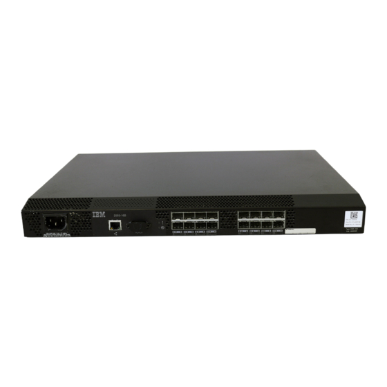
scale: 5/16" = 1" IOIOI Figure 1. Port side of the SANB16-2 switch AC power receptacle Ethernet port Serial port Fibre Channel ports (16) Non-port side of the SAN16B-2 switch The non-port side of the switch is used solely for air flow and for serial number labels. -
Page 26: Advanced Security
Advanced Security Activation is designed to enables policy-based security mechanisms integrated within Fabric Operating System V2.6, and later. To enable advanced security capabilities, all switches within the IBM SAN Switch Fabric must be configured with their respective Fabric operating system version (2.6 or later) before activating the Advanced Security feature license key. -
Page 27: Trunking Groups
Trunking Group 1 Trunking Group 3 Trunking Group 2 Trunking Group 4 Figure 2. Trunking groups Trunking group Port numers Group 1 Ports 0–3 Group 2 Ports 4–7 Group 3 Ports 8–11 Group 4 Ports 12–15 Note: For more information about trunking, refer to the Brocade Fabric OS Administrator’s Guide. - Page 28 SAN16B-2 Installation, Service, and User’s Guide...
-
Page 29: Chapter 2. Installing And Configuring The San16B-2
– Four rubber mounting feet, required for setting up the switch as a stand-alone unit – One slide-rail rack mount kit, with instructions – SFP transceivers (quantity depending upon features ordered) – SAN16B-2 Installation, Service, and User’s Guide (this document). – IBM documentation CD © Copyright IBM Corp. 2005... -
Page 30: Installation And Safety Considerations
Installation and safety considerations Use this section to prepare your site for a safe and successful installation. Attention: Although the switch has been designed for customer installation and replacement procedures, you must first ensure that the rack into which the switch is to be installed is also customer accessible. -
Page 31: Electrical Requirements
1. Unpack the switch and verify that all items listed in “Items included with the switch” on page 7 are present and undamaged. Note: If any items are damaged or missing, contact the IBM Quality Hotline toll-free at 1-800-442-6773 within the United States and Canada, or direct dial 770-858-8459 in other locations. -
Page 32: Installing A San16B-2 Into An Eia Cabinet
Installing a SAN16B-2 into an EIA cabinet Attention: Refer to “Rack safety” on page xiii for danger and caution notices related to rack and cabinet installations. You can install the rack mount kit in either of two ways: v To allow the port side of the switch to slide out of the exhaust-air side of the cabinet. -
Page 33: Rack Assembly
Outer Slide EIA Rack Rail Inner Slide Detail A Front of Switch Detail A SJ000153 Figure 3. Rack assembly 1. Unpack the rack-mount kit and verify that all ordered items and parts are present and undamaged. See Table 4 for a list of parts and the quantities supplied. -
Page 34: Separating The Inner And Outer Rails
2. Separate the inner and outer slides. a. Open one of the slides until the lock engages. b. Press the lock release lever ( 1 in Figure 4) and remove the inner rail from the outer rail. SJ000046 Figure 4. Separating the inner and outer rails. c. -
Page 35: Mounting The Moving Portion Of The Slide And Mounting Brackets To The Switch
Front SJ000047 Figure 5. Mounting the moving portion of the slide and mounting brackets to the switch c. Repeat step 3a on page 12 and step 3b on page 12 for the second inner rail on the other side of the switch chassis. 4. -
Page 36: Mounting The Fixed Portion Of The Rail And The Locking Ears To The Rack
SJ000048 Figure 6. Mounting the fixed portion of the rail and the locking ears to the rack 6. Install the outer (larger) slides in the rack, as shown in Figure 6. a. At the desired height, install the five M5 nut clips 5 . Put three M5 nut clips in the front of the rack and two in the back. -
Page 37: Inserting Slides Into The Rack Rails
SJ000049 Figure 7. Inserting slides into the rack rails b. Check the alignment of the slides by sliding the switch in and out of the rack. Any difficulty moving the switch indicates lateral stress or misalignment. If this situation occurs, adjust the slide positions until the movement is smooth. -
Page 38: Cabling And Configuring The San16B-2
Cabling and configuring the SAN16B-2 You must configure the switch to ensure correct operation within a network and fabric. For instructions about how to configure the switch to operate in a fabric that contains switches from other vendors, refer to the Brocade Fabric OS Administrator’s Guide. -
Page 39: San16B-2 Port Side Details
4. “Creating an Ethernet connection and logging in” on page 19 5. “Modifying the domain ID (optional)” on page 19 6. “Installing the SFP transceivers” on page 19 7. “Connecting the cables” on page 20 Creating a serial connection Before you can begin configuring the switch, you must create a connection by way of the serial port. -
Page 40: Setting The Ip Address
Powering up the switch and logging in After you create the serial connection using the steps in “Creating a serial connection” on page 17, provide power to the switch by completing the steps below. Note: Power is supplied to the switch as soon as the power supply is connected to a power source, you should then see POST messages. -
Page 41: Installing The Sfp Transceivers
Note: Any time the serial port is not in use, install the protective plug to keep foreign material out of the port. Creating an Ethernet connection and logging in Create an Ethernet connection to the switch by performing the following steps: 1. -
Page 42: Verifying The Configuration
2. Position a transceiver so that it is oriented correctly and insert it into a port until the latching mechanism clicks. The transceivers are keyed to ensure correct orientation. If a transceiver does not install easily, ensure that it is correctly oriented. -
Page 43: Chapter 3. Operating The San16B-2
The pairs of port LEDs are located in the array in the same relative positions as the ports. The port number of the associated Fibre Channel port appears between the Port Status and Port Speed LEDs. © Copyright IBM Corp. 2005... -
Page 44: Led Patterns And Recommended Actions
Figure 9 shows the location of the LEDs on the port side of the switch. See “LED patterns and recommended actions” for details about how to interpret the activity of these LEDs, and possible actions to take. scale: 5/1 6" = 1" IOIOI IOIOI Figure 9. - Page 45 Switch is off or power supply has Verify that the system is on and has failed. completed booting. If the system is on, the unit is faulty. Contact IBM Support. Steady green Switch is on and power supply is No action required.
-
Page 46: Port Led Patterns During Normal Operation
Port LED patterns Each port has two LEDs: a port speed and a port status indicator. These LEDs are located below both rows of ports, and each set is labeled with the port number. Table 7 shows the LED location, color, and meaning for these port LEDs. Table 7. -
Page 47: Post And Boot Specifications
Table 8. Ethernet LED patterns LED name, location LED color Status of hardware Recommended action Ethernet link Amber Link is valid. No action required. Blinking amber Traffic. Ethernet Speed No light Port speed is 10 Mb/sec No action required. Steady green Port speed is 100 Mb/sec. -
Page 48: Interpreting Post Results
Enter. If the switch prompt still does not display, open another Telnet session or access the switch through another management tool. If this is not successful, the switch did not successfully complete POST. Contact IBM Service for repair. 3. Review the switch system log for errors. Any errors detected during POST are written to the system log, which is accessible through the errShow command. -
Page 49: Chapter 4. Monitoring And Maintaining The Sanb16-2
This includes tests of internal connections and circuitry, fixed media, and the SFPs and cables in use. The tests are implemented by command, either through a Telnet session or through a terminal set up for a serial © Copyright IBM Corp. 2005... -
Page 50: Installing, Removing, And Testing Sfps
connection to the switch. Some tests require the ports to be connected by external cables, to allow diagnostics to verify the serializer/deserializer interface, SFP, and cable. All diagnostic tests are run at link speeds of 1, 2, and 4 Gbit/sec, depending on the speed of the link being tested. -
Page 51: Installing An Sfp
Installing an SFP If your switch did not come with installed SFPs, or you are replacing older ones, follow the instructions below to install your SFPs. Note: SFPs are keyed so that they can be inserted only in the correct orientation. The ports in the top row the switch are oriented in one direction, and the lower row of ports are oriented in the opposite direction. -
Page 52: Installing A Plastic Tab Type Sfp
Figure 14. Installing a plastic tab type SFP Figure 15. Installing a wire bale type SFP Switch chassis Wire bale (in open, unlocked position) 5. For SFPs with wire bales, close the bale to lock it in place (see as shown in 2 in Figure 15. -
Page 53: Locking Wire Bale Sfp In Place
scale: 1/2" = 1" I O I Figure 16. Locking wire bale SFP in place Switch chassis Wire bale (in closed, locked position) 6. Repeat this procedure for the remaining SFPs and ports, as required. For the top row of ports, SFPs will be oriented as shown in Figure 14 on page 30 and Figure 15 on page 30. -
Page 54: Removing Sfp Modules
2. Holding the cable by its connector, align the cable end with the SFP module, and push it into the SFP (see Figure 18) until the connector clicks in place . Figure 18. Inserting a fiber-optic cable into an SFP module Removing SFP modules In some cases you might need to remove an SFP module, either because it is no longer needed or because you must replace it. -
Page 55: Removing A Fiber-Optic Cable
Figure 20. Removing a fiber-optic cable 3. Replace the protective caps on the cable ends. 4. If you are leaving the SFP in place, replace the protective cap on the SFP. Removing a plastic tab type SFP Follow the steps below to remove a plastic tab type SFP. 1. -
Page 56: Removing An Sfp Module, Plastic Tab Type
Figure 22. Removing an SFP module, plastic tab type 3. Replace the protective cover on the SFP module. 4. Place the SFP module into a static-protective package. 5. Replace the protective cover on the switch port. 6. Repeat this procedure for any additional SFPs, as required. Removing a wire bale type SFP Follow the steps below to remove a wire bale type SFP. -
Page 57: Unlocking The Sfp Module Latch, Wire Bale Type
Open Bale Bale Figure 23. Unlocking the SFP module latch, wire bale type 2. Grasping it by the bale, gently but firmly pull the SFP out of the port (see 2 in Figure 23). 3. Replace the protective cover on the SFP module. 4. - Page 58 SAN16B-2 Installation, Service, and User’s Guide...
-
Page 59: Appendix A. Product Specifications
You can use the serial port to connect to a computer workstation to configure the switch IP address without connecting to the fabric. The serial port's parameters are 9600 baud, 8 data bits, no parity, 1 stop bit, and no flow control. © Copyright IBM Corp. 2005... -
Page 60: Power Supply Specifications
The port requires a straight (extension) serial cable with a female 9–pin subminiature-D connector. Only pins 2, 3, and 5 are supported. Power supply specifications The power supply is universal and capable of functioning worldwide without using voltage jumpers or switches. It meets IEC 61000-4-5 surge voltage requirements and is autoranging in terms of accommodating input voltages and line frequencies. -
Page 61: Weight And Physical Dimensions
Weight and physical dimensions Table 12 lists the weight and physical dimensions of the SAN16B-2. Table 12. Switch specifications Dimension Value Height 1U = 4.29 cm (1.69 in.) Width 42.85 cm (16.87 in.) Depth 30.734 cm (12.10 in.) Weight 4.0 kg (8.8 lb) Memory specifications The switch memory specifications are listed in Table 13. - Page 62 SAN16B-2 Installation, Service, and User’s Guide...
-
Page 63: Appendix B. Power Cord Information
IBM. Figure 24 on page 43 shows the plugs associated with each power cord. These feature codes and part numbers apply to products purchased through IBM or IBM resellers. For products purchased through the Web at www.ibm.com, the power cord part numbers are different. -
Page 64: Types Of Plugs
PN 02K0546 Note: Part number 6952300 is the default power cord for the countries or regions listed. If you do not specify a power cord when you place your order, IBM provides this power cord. Types of plugs Figure 24 on page 43 shows the plugs for the power cords in Table 15 on page 41. -
Page 65: Notices
Consult your local IBM representative for information on the products and services currently available in your area. Any reference to an IBM product, program, or service is not intended to state or imply that only that IBM product, program, or service may be used. Any functionally equivalent product, program, or service that does not infringe on any IBM intellectual property right may be used instead. - Page 66 The materials at those web sites are not part of the materials for this IBM product and use of those web sites is at your own risk.
-
Page 67: Trademarks
IBM is not responsible for any radio or television interference caused by unauthorized changes or modifications to this equipment. Unauthorized changes or modifications could void the user’s authority to operate the equipment. -
Page 68: Avis De Conformité À La Réglementation D'industrie Canada
IBM cannot accept responsibility for any failure to satisfy the protection requirements resulting from a non-recommended modification of the product, including the fitting of non-IBM option cards. This product has been tested and found to comply with the limits for Class A Information Technology Equipment according to European Standard EN 55022. -
Page 69: People's Republic Of China Class A Electronic Emission Statement
People’s Republic of China Class A Electronic Emission Statement Japan VCCI Class A ITE Electronic Emission Statement Korea Class A Electronic Emission Statement Notices... - Page 70 SAN16B-2 Installation, Service, and User’s Guide...
-
Page 71: Glossary
It also provides additional definitions of technical terms and abbreviations. If you do not find the alias AL_PA. An arbitrated loop physical address term you are looking for, see the IBM Terminology (AL_PA) value recognized by a loop port (L_port) in located at http://www.ibm.com/ibm/terminology/ addition to the AL_PA assigned to the port. - Page 72 asynchronous transfer mode (ATM). A method of blade. A component that provides application-specific transmission in which the sending and receiving of data services and components. A blade is typically a hot is controlled by control characters such as a start bit swappable hardware device.
- Page 73 Challenge Handshake Authentication Protocol Common Information Model (CIM). An (CHAP). (1) An authentication protocol that protects implementation-neutral, object-oriented schema for against eavesdropping by encrypting the user name and describing network management information. The password. (2) Allows remote servers and clients to Distributed Management Task Force (DMTF) develops securely exchange authentication credentials.
- Page 74 DB-9 connector. A 9–pin version of the RS–232C port EIA rack. A storage rack that meets the standards set interface. by the Electronics Industries Alliance (EIA). dc. Direct current. electromagnetic compatibility (EMC). The design and test of products to meet legal and corporate defined zone configuration.
- Page 75 ports (N_ports). Composed of one or more related FC-AL-3. The Fibre Channel Arbitrated Loop standard sequences, and can work in either one or both defined by ANSI. Defined on top of the FC-PH directions. standards. expansion port (E_port). A port is designated an FCC.
- Page 76 Fibre Channel transport. A protocol service that supports communication between Fibre Channel service providers. See also Fibre Channel service protocol. gateway. Hardware that connects incompatible networks by providing the necessary translation for both field replaceable unit (FRU). An assembly that is hardware and software.
- Page 77 host bus adapter (HBA). The interface card between is called a trunking group; each port employed in a a server or workstation bus and the Fibre Channel trunking group is called a trunking port. See also master network. port. hot-pluggable. A field replaceable unit (FRU) that can isolated E_port.
- Page 78 local area network (LAN). A network that connects LPSM. See loop port state machine. several devices into a limited area (such as a single LSAN. Logical storage area network. An LSAN building or campus) and that can be connected to a enables device and storage connectivity that spans two larger network.
- Page 79 node port (N_port). A port on a node that can path selection. The selection of a transmission path connect to a Fibre Channel port or to another N_Port in through the fabric. Switches use the Fibre Channel a point-to-point connection. shortest path first (FSPF) protocol.
- Page 80 primitive signal. A part of an ordered set that indicates events. See also ordered set. RAID. See redundant array of independent disks. principal switch. The switch that assumes the responsibility to assign domain IDs. The role of principal RAM. See random access memory. switch is negotiated after a “build fabric”...
- Page 81 ROM. See read only memory. Gbps link speeds. Can also refer to the type of gigabit interface converter (GBIC) or small form-factor route. As applies to a fabric, the communication path pluggable (SFP). See also long wavelength. between two switches. Can also apply to the specific path taken by an individual frame, from source to SID.
- Page 82 switch. Hardware that routes frames according to Tx. Transmitted. Fibre Channel protocol and is controlled by software. switch name. The arbitrary name assigned to a switch. U. Unit of measure for rack-mounted equipment. switch port. A port on a switch. Switch ports can be UDP.
- Page 83 wide area network (WAN). A network that provides communication services to a geographic area larger than that served by a local area network or a metropolitan network, and that can use or provide public communications facilities. workstation. A computer used to access and manage the fabric.
- Page 84 SAN16B-2 Installation, Service, and User’s Guide...
-
Page 85: Index
20 Ethernet connection 19 Boot 25 Ethernet LED patterns 24 Boot steps 25 Brocade documents xvii IBM product and model number matrix xviii Fabric Watch 3 Brocade documents xvii facility requirements 8 feature activation additional port 3 Full Fabric 3... - Page 86 SANB16-2 27 notices 43 management features 27 trademarks 45 management options 27 IBM product and model number matrix xviii memory specifications 39 installation minimum bend radius instructions 10 fiber-optic cables 20 rack xiii modifying the domain ID 19...
- Page 87 product (continued) SAN16B-2 switch introduction 1 introduction 1 recycling xv SANB16-2 specifications 37 maintaining 27 product disposal xv management features 27 product documents xvii management options 27 product recycling xv monitoring 27 product specifications 37 product specifications data transmission ranges 37 See product specifications Fibre Channel ports 37 serial connection 17...
- Page 88 usage restrictions xii verify configuration 20 warning cable xvi warning, cable xvi Web sites xviii WEEE directive xv weight 39 who should read this document xvii SAN16B-2 Installation, Service, and User’s Guide...
- Page 89 Thank you for your responses. May we contact you? h Yes h No When you send comments to IBM, you grant IBM a nonexclusive right to use or distribute your comments in any way it believes appropriate without incurring any obligation to you. Name...
- Page 90 Readers’ Comments — We’d Like to Hear from You Cut or Fold Along Line GC26-7753-00 Fold and Tape Please do not staple Fold and Tape _ _ _ _ _ _ _ _ _ _ _ _ _ _ _ _ _ _ _ _ _ _ _ _ _ _ _ _ _ _ _ _ _ _ _ _ _ _ _ _ _ _ _ _ _ _ _ _ _ _ _ _ _ _ _ _ _ _ _ _ _ _ _ _ _ _ _ _ _ _ _ _ _ _ _ _ _ _ _ _ _ _ _ _ _ _ _ _ _ NO POSTAGE NECESSARY IF MAILED IN THE...
- Page 92 Part Number: 22R5515 Printed in USA GC26-7753-00...
Need help?
Do you have a question about the SAN16B-2 - TotalStorage Express Model Switch and is the answer not in the manual?
Questions and answers