Table of Contents
Advertisement
Advertisement
Table of Contents
Troubleshooting

Related Manuals for Omron Z302-E1-03


Summary of Contents for Omron Z302-E1-03
- Page 1 Vision Sensor User's Manual Cat. No. Z302-E1-03...
-
Page 2: Application Considerations
APPLICATION CONSIDERATIONS (Please Read) Introduction User's Manual Installation and Connections Taking Images Setting Up Inspections Testing and Saving Settings Operation Convenient Functions Communications with External Devices Troubleshooting Appendices Vision Sensor... - Page 3 LOSS OF PROFITS OR COMMERCIAL LOSS IN ANY WAY CONNECTED WITH THE PRODUCTS, WHETHER SUCH CLAIM IS BASED ON CONTRACT, WARRANTY, NEGLIGENCE, OR STRICT LIABILITY. In no event shall responsibility of OMRON for any act exceed the individual price of the product on which liability is asserted.
- Page 4 Performance data given in this document is provided as a guide for the user in determining suitability and does not constitute a warranty. It may represent the result of OMRON’s test conditions, and the users must correlate it to actual application requirements. Actual performance is subject to the OMRON Warranty and Limitations of Liability.
-
Page 5: Meanings Of Signal Words
Meanings of Signal Words The following signal words are used in this manual. Indicates a potentially hazardous situation which, if not avoided, will result in minor or moderate injury, or may result in serious injury or death. Additionally there may be significant property damage. -
Page 6: Precautions For Safe Use
Precautions for Safe Use The following points are important to ensure safety, so make sure that they are strictly observed. 1. Installation Environment • Do not use the product in environments where it can be exposed to inflammable/explosive gas. • To secure the safety of operation and maintenance, do not install the product close to high-voltage devices and power devices. - Page 7 5. Other • Do not use this product in safety circuits associated with nuclear power and human life. • Do not disassemble, repair, modify, deform by pressure, or incinerate this product. • Dispose of this product as industrial waste. • Connect the special products (Sensor, Touch Finder, Cables). The product might break down or malfunction if you use a part not included in the special products.
-
Page 8: Precautions For Correct Use
Precautions for Correct Use Observe the following precautions to prevent failure to operate, malfunctions, or undesirable effects on product performance. 1. Installation Site Do not install this product in locations subjected to the following conditions: • Ambient temperature outside the rating •... - Page 9 5. Maintenance and Inspection Do not use thinner, benzene, acetone or kerosene to clean the Sensor and Touch Finder. If large dust particles adhere to the Camera, use a blower brush (used to clean camera lenses) to blow them off. Do not use breath from your mouth to blow the dust off.
-
Page 10: Table Of Contents
Table of Contents 1. Introduction 1-1 FQ-series Vision Sensors........14 1-2 Measurement Process . - Page 11 5. Testing and Saving Settings 5-1 Performing Test Measurements....... . . 86 5-2 Shortening the Measurement Takt Time .
- Page 12 10. Appendices 10-1 Menu Tables..........172 10-2 External Reference Parameters .
- Page 13 FQ User’s Manual...
-
Page 14: Introduction
Introduction 1-1 FQ-series Vision Sensors ........14 1-2 Measurement Process . -
Page 15: Fq-Series Vision Sensors
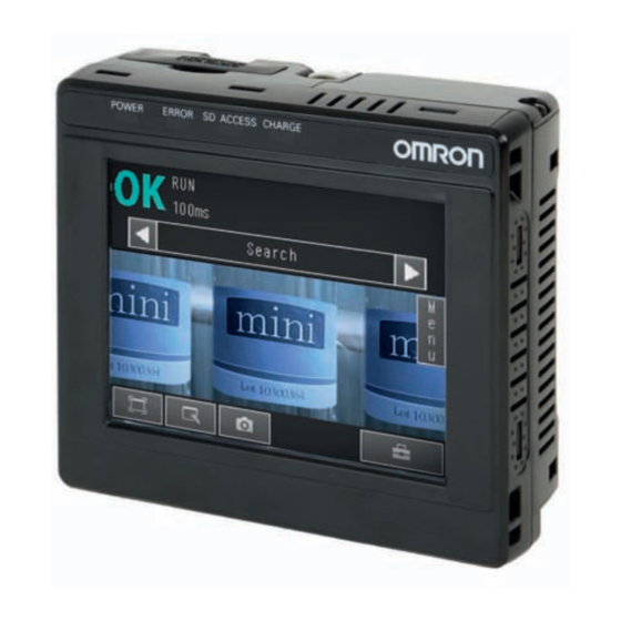
1-1 FQ-series Vision Sensors FQ-series Vision Sensors are real-color Vision Sensors with integrated processing. Once configured, they are used stand-alone for quality inspection of presence, position, and other product characteristics. To set up or monitor the sensors, either the touch screen based console 'Touch Finder' or a 'PC Tool' can be used. Setup, Image Confirmation, and Logging Tools Touch Finder FQ Vision Sensor... -
Page 16: Measurement Process
1-2 Measurement Process This section describes the basic flow of the measurement process. • The measurement is started by inputting a trigger signal from an external device. Trigger input • Images are taken according to the trigger. Take image • The image is measured to see if it matches the configured settings. •... -
Page 17: Startup Display And Display Elements
1-3 Startup Display and Display Elements Startup Display The Sensor is automatically detected by the Touch Finder when power supply to the Sensor and Touch Finder is turned ON. The Auto Connect Display will appear if the Sensor can- not be detected. Check that cables are connected cor- rectly to the Sensor and Touch Finder, and then press [Auto connect]. -
Page 18: Display Elements
Display Elements This Sensor has a Setup Mode and a Run Mode. Refer to the following information for menu items. p. 172 Setup Mode In Setup Mode, you can set the image conditions, judgement parameters, and I/O settings for the Sensor. The name of the Sensor being set up is displayed. -
Page 19: Basic Operational Flow
1-4 Basic Operational Flow The following flow shows the basic operation of FQ-series Vision Sensors. Section 2 Installation Connections and Wiring and Connections Section 1 Starting the Sensor 1-3 Startup Display and Display Elements Image Setup Section 3 Taking ([Image] Tab Page) Images Inspection Setup Section 4 Setting Up... -
Page 20: Installation And Connections
Installation and Connections 2-1 System Configuration ........20 2-2 Part Names and Functions . -
Page 21: System Configuration
2-1 System Configuration Parallel Interface Connection Trigger Sensor FQ Vision Sensor Setup Tool Touch Finder or PC Tool FQ Ethernet Cable I/O Cable 24-VDC power supply 24-VDC power supply Connecting to Ethernet PLC to control Sensor Setup Tool Switching Hub Touch Finder or PC Tool Standard RJ45 Ethernet Cable Standard RJ45... -
Page 22: Part Names And Functions
2-2 Part Names and Functions FQ Vision Sensor Name Description Lighting LEDs for illumination Camera lens This lens can be focused. I/O Cable connector An I/O Cable is used to connect the Sensor to the power supply and exter- nal I/O. Ethernet cable connector An Ethernet cable is used to connect the Sensor to external devices such as PLCs, the Touch Finder, or computers. - Page 23 Touch Finder (11) (12) (10) Name Description Operation POWER Lights green when the Touch Finder is turned ON. indicators ERROR Lights red when an error occurs. 9-1 Error Table p. 168. SD ACCESS Lights yellow when an SD card is inserted. Flashes yellow when the SD card is being accessed.
-
Page 24: Installation
2-3 Installation Installing the Sensor Installation Procedure Align the tabs on one side of the Mounting Bracket with the slot on the Sensor. Mounting The FQ-XL Mounting Bracket can be attached to the back, Bracket side, or front of the Sensor. Press the Mounting Bracket onto the Sensor until the oth- er tabs click into place. -
Page 25: Installation Precautions
Important • There is a certain amount of deviation among Sensors in the center of the optical axis. For this reason, when install- ing the Sensor, check the center of the image and the field of view on the LCD monitor of the Touch Finder and in the PC Tool. - Page 26 Mounting to DIN Track Installation Procedure Press the slider on the Touch Finder to the top. Hook the clip at the top of the Touch Finder on to the DIN Track. Press the Touch Finder onto the DIN Track until the bottom clip clicks into place.
- Page 27 Press the slider up on the Touch Finder. Create holes in the panel for mounting. Refer to the following page for hole dimensions. p. 195 Connect the cable to the Touch Finder. Mount the Touch Finder with the Panel Mount Adapter from the front of the panel.
- Page 28 Connect the Neck Strap or Hand Strap to the Mini-strap. Mini-strap Neck Strap or Hand Strap FQ User’s Manual Installation...
-
Page 29: Wiring
2-4 Wiring Wiring the Sensor Connect the I/O Cable to the I/O Cable connector located at the bottom of the Sensor. Brown Power supply Blue Black OUT0 (OR) Orange OUT1 (BUSY) OUT2 (ERROR) Light blue Pink TRIG Gray FQ-WD0@@ Green I/O Cable White Purple... - Page 30 I/O Signal Circuit Diagrams Brown Power supply (24 VDC) Brown Power supply (24 VDC) Pink TRIG Load Black OUT0 (OR) Gray Orange Green OUT1 (BUSY) Light blue OUT2 (ERROR) White Purple 24 VDC Blue Yellow GND (0V) Pink TRIG 24 VDC Gray Light blue Green...
-
Page 31: Power Supply Wiring
Wiring the Touch Finder Power Supply Wiring Connecting the Power Supply Loosen the two terminal screws using a Phillips screwdriver. Attach crimp terminals to the power lines. Secure the positive and negative lines as indicated 24 VDC using M3 screws. −... -
Page 32: Charging The Battery
Charging the Battery This section describes how to charge and install the FQ-D31 Battery and provides applicable precautions. Charge the Battery while it is attached to the Touch Finder. Use the AC adapter to charge the battery. Mounting the Battery in the Touch Finder Remove the screw from the battery cover on the top of the Touch Finder, slide the cover in the direction of the arrow, and open the battery cover. - Page 33 Important • If the Touch Finder (FQ-D31) will be installed permanently or semi-permanently, remove the Battery (FQ-BAT1). If the rated temperature is exceeded with the Battery inserted, the protective circuit may activate and stop the Touch Finder. • The battery complies with the following recycling regulation. Japan Taiwan Li-ion00...
-
Page 34: Setting Up Ethernet
Set the IP address and subnet mask according to the network where the external devices, such as PLCs, are connected. Note If you connect OMRON CS/CJ-series PLCs to the Ethernet, the following default IP addresses are assigned to the PLCs. • IP address: 192.168.250.node_address... - Page 35 Right-click the [Local Area Connection] Icon and select [Properties]. On the [General] Tab Page, double-click Internet Proto- col (TCP/IC). Select the Use the following IP address Option and en- ter the following IP address and subnet mask. • IP address: 10.5.5.101 •...
-
Page 36: Taking Images
Taking Images 3-1 Selecting a Sensor for Configuration......36 3-2 Adjusting Image Quality ........37 3-3 Adjusting the Object Position . -
Page 37: Selecting A Sensor For Configuration
3-1 Selecting a Sensor for Configuration If multiple Sensors are connected to a single Touch Finder or computer, you can select the Sensor that you want to set up. Press [Run]. This will enable setting the current Sensor into RUN Mode before selecting another Sensor. -
Page 38: Adjusting Image Quality
3-2 Adjusting Image Quality Adjusting the Focus [Image] − [Camera setup] Display the Camera Setup Display. The focus can be seen as a numerical value. The higher the value, the better the focus. Focus Level Manually adjust the focus using the focus adjust- Focus adjustment screw ment screw on the Sensor while checking the image Turn clockwise to focus on closer objects. -
Page 39: Adjusting The Brightness
Adjusting the Brightness To achieve stable measurements, the brightness of the camera image must be adjusted so that the characteristic to be measured is clearly visible. Dark Bright Brightness of image [Image] − [Camera setup] ] − [Brightness] on the right side of the dis- Press [ play. - Page 40 Taking Clear Images of Moving Objects For quick moving objects, the effect of blurring can be reduced by decreasing the exposure time. Slow Fast Moving speed Exposure time 1/30,000 1/250 [Image] – [Camera setup] – [ ] – [Brightness] Adjusting the Brightness: p. 38 Important The image becomes darker the smaller the exposure time.
- Page 41 Observe the following precautions. • Use the HDR function only for objects that are not moving to avoid image blurring. Several images are taken with different shutter speeds and combined. If the object moves while the image is being taken, the image will become blurred. •...
- Page 42 Using the top section as a pivot point, pull down the filter so that it attaches to the Sensor. Adjusting the Colors of the Image (White Balance) If external lighting is used, the image may appear as having different colors than the actual object. If this is the case, adjust the white balance.
-
Page 43: Adjusting The Object Position
3-3 Adjusting the Object Position If objects are moving, the position in the image of the characteristic that is to be measured will vary according to the timing of the trigger signal. The FQ Vision Sensor offers two different ways to adjust this position variation. - Page 44 Press [Teach]. Drag the rectangle to move it. Adjust the image so that the measurement object is in the center. Press [ ] – [Model region]. Move the rectangle so that the characteristic part for position compensation is inside it. Press [OK].
- Page 45 Measures to Stabilize Position Correction • Low Mark Contrast and Inconsistent Correlations Areas with high contrast are registered as model registration sections. The adjustment procedure is the same as for the search function. Or, adjust the brightness to increase the contrast of the mark. Making dark images brighter: p.
- Page 46 [Image] − [Trigger setup] − [Trigger delay] A TRIG signal is input. Images are input continuously. Select the image with the measurement object in the center using [ ] and [ Press the image. Press [OK]. Note The delay time can be set using the adjustment bar or by directly entering a value. Move the bar to the left or right.
-
Page 47: Preventing Mutual Interference Of Multiple Sensors
3-4 Preventing Mutual Interference of Multiple Sensors When the same trigger signal is input to multiple Sensors, the lighting from one Sensor may affect the measurements of the other Sensors. This is called mutual interference. This kind of interference can be prevented offsetting the image input timing of each Sensor from when the trigger signal is received. -
Page 48: Setting Up Inspections
Setting Up Inspections 4-1 Inspection Item Selection Guide ......48 4-2 Setup Procedure for Inspection Items ......49 4-3 Configuring Inspection Items . -
Page 49: Inspection Item Selection Guide
4-1 Inspection Item Selection Guide The FQ Vision Sensor uses inspection items to judge measurement objects. There are five different measurement objects. Select the best inspection items for the characteristics of the measurement object that are being judged. Inspection Example Inspection Refer- items used... -
Page 50: Setup Procedure For Inspection Items
4-2 Setup Procedure for Inspection Items The basic steps for setting up inspection items are shown below. Configuring Inspection Items Step 1 Teaching Step 2 Setting Judgement Parameters Step 3 If measurements are unstable Setting Detailed Items Step 4 Re-teaching Step 5 Note •... -
Page 51: Configuring Inspection Items
4-3 Configuring Inspection Items Adding New Inspection Items Press [Inspect] − [Inspection]. Press an unused inspection item number. Press [Add item.] on the menu. Select an inspection item, such as [Search]. When registering multiple inspection items, press the inspection item number after 1.--- and set it in the same way. - Page 52 Modifying Existing Inspection Items Press the number of the inspection item to be set. Press [Modify] on the menu. Deleting Inspection Items Press the number of the inspection item to be delet- Press [Delete] on the menu. Note Executing Similar Measurements in Different Places →...
-
Page 53: Inspecting With The Search Inspection Item
4-4 Inspecting with the Search Inspection Item Search Inspection Item This inspection item is used to perform inspections for shapes or for presence. The image pattern that is to be measured is registered in advance and measurements are performed to see if the pattern is present or if the shape is different. - Page 54 Step 2 Teaching Teaching means to store the region and partial image as reference data for the measurement. − [Add item.] − [Search] − [Settings] Tab Page − [Inspection] [Inspect] Press [Teach]. Place the object that is to be used as the measure- Drag a corner to Drag the rectangle size the rectangle.
- Page 55 Unstable Search Results Inclined Measurement Objects Adjust the [Angle range] parameter to increase the range in which a search is made for the model. The Search inspection item judges whether an image is OK or NG according to the correlation with a previously registered image pattern.
- Page 56 Editing the Model and Measurement Regions This section describes how to edit the following regions. Model registration region Measurement region (region that is searched for the model) Important If the model region is changed, perform teaching again. p. 53 Changing the Model Registration Region to a Shape Other Than a Rectangle One rectangular region is registered as the default model registration region.
- Page 57 Masking Parts of the Model The model registration region can be formed freely by combining enabled and disabled regions. Example: Figure 1: Enabled range Figure 2: Disabled range The gray section is the model region. Figure 3: Enabled range − [Search] − [Modify] − [Settings] Tab Page − [Teach] − [ ] − [Model −...
- Page 58 Changing the Measurement Region The region within which the model is searched can be changed. In the default settings, the whole display is set as the measurement region. − [Inspection] − − − − [Inspect] [Search] [Modify] [Settings] Tab Page [Teach] ] −...
- Page 59 Errors Errors in Teaching A teaching error message will appear if the contrast of the image within the model registration region is too low. Select a region with a larger contrast between light and dark areas compared to the region that was registered as the model and re-register it as the model.
-
Page 60: Inspecting With The Edge Position Inspection Item
4-5 Inspecting with the Edge Position Inspection Item Edge Position This inspection item is used to inspect positions. For example, it can be used to see if a label is attached at the correct position or if a product is set in the correct position. Places where the color changes greatly are called edges. - Page 61 Step 2 Teaching Teaching means to store the region and the edge position in the region as reference data for the measurement. − [Add item.] − [Edge Position] − [Settings] Tab Page − [Inspection] [Inspect] Press [Teach]. Place the object that is to be used as the measure- The arrow in the middle shows the direction for detecting an edge.
- Page 62 Unstable Edge Position Results There Is an Edge But It Cannot Be Detected − [Edge Position] − [Modify] − [Details] Tab Page − [Inspection] [Inspect] Parameter Setting Description Edge level Range: 0 to 100 Set the color change level to detect as an edge. Default: 50 The edge point is found based on a threshold that is set for a color change.
- Page 63 Screen Display When the Edge Level and Noise Level Are Changing A bar showing the threshold level moves up and down on the graphic as the edge level/noise level value changes. A cross-key cursor will also appear at the detected edge position. Edge level Noise level Undesired Edge Position Is Automatically Detected When Teaching...
- Page 64 • Measurement Data That Can Be Used for External Outputs and Calculations The following values can be used as measurement data and output to external devices via the Ethernet or used in calculations. Expression text string Data name Description Data range −2: No judgement (not measured), Judgement This is the judgement result.
-
Page 65: Inspecting With The Edge Width Inspection Item
4-6 Inspecting with the Edge Width Inspection Item Edge Width Inspection Item This inspection item is used to measure dimensions. Places where the color changes greatly are called edges. The distance between two edges is called the edge width. Sample Settings Sample Measurement Edges are searched from two directions and the... - Page 66 Step 2 Teaching Teaching means to store the region and the edge width in the region as reference data for the measurement. − [Add item.] − [Edge Width] − [Settings] Tab Page − [Inspection] [Inspect] Press [Teach]. Place the object that is to be used as the measure- The middle arrow is the direction for ment reference in front of the camera.
- Page 67 Increasing Edge Width Processing Speed Make the measurement region smaller to reduce the processing time. Changing the measurement region: p. 57 Measurement Data That Can Be Used for External Outputs and Calculations The following values can be output to external devices or used in calculations as measurement data. Expression text string Data name Description...
- Page 68 Edge Not Found The measured edge width will be 0. Perform the following. • If a color was specified, make sure the color of the measurement object has not changed from the specified color. • Set the color again if necessary. •...
-
Page 69: Inspecting With The Area Inspection Item
4-7 Inspecting with the Area Inspection Item Area Inspection Item This inspection item is used to measure sizes. It measures the amount of a color within the measurement region. The size is calculated as a number of pixels and it is called the area. Sample Settings Sample Measurement Judges according to the... - Page 70 Step 2 Teaching Teaching means to store the region and the color area in the region as reference data for the measurement. − [Add item.] − [Area] − [Settings] Tab Page − [Inspection] [Inspect] Press [Teach]. Drag the rectangle Drag a corner to to move it.
- Page 71 Unstable Area Results The Desired Color Cannot Be Detected Add a specific color or enlarge the color range. Extraction Is Automatically Performed for an Undesired Color When Teaching Manually set the color for which to measure the area. − [Inspection] − −...
- Page 72 Increasing Processing Speed for Area Make the measurement region smaller to reduce the processing time. Changing the measurement region: p. 57 Measurement Data That Can Be Used for External Outputs and Calculations The following values can be used as measurement data and output to external devices via the Ethernet or used in calculations.
-
Page 73: Inspecting With Color Data Inspection Item
4-8 Inspecting with Color Data Inspection Item Color Data Inspection Item This inspection item is used to perform inspections for foreign matter with a different color or for presence. The region is set for a portion of the image with the color that is to be measured. This region is called the measurement region. - Page 74 Step 2 Teaching Teaching means to store the region and the average color in the region as reference data for the measurement. − [Add item.] − [Color Data] − [Settings] Tab Page − [Inspection] [Inspect] Press [Teach]. Drag the rectangle to move it. Drag a corner to Place the object that is to be used as the measure- size the rectangle.
- Page 75 Measurement Data That Can Be Used for External Outputs and Calculations The following values can be used as measurement data and output to external devices via the Ethernet or used in calculations. Expression text string Data name Description Data range −2: No judgement (not measured), Judgement This is the judgement result.
-
Page 76: Calculations And Judgements Using Inspection Item Data
4-9 Calculations and Judgements Using Inspection Item Data You can set inspection item judgement results and measurement data with the Calculation menu command to use them in basic arithmetic operations and functions. The judgement results of the calculations are reflected in the overall judgement. - Page 77 Outputting the Calculation Results The overall judgement (JG) of the calculations are reflected in the overall judgement of the inspection item. The calculation results (D0 to 31) can be output as Ethernet outputs or it can be output by using logging. Individual Inspection items* Overall judgement...
- Page 78 Examples for Calculation Finding the Distance between Two Measured Points This example finds edge position 2 by detecting the two edge positions of inspection item 0 and inspection item 1, and calculates the distance between the two points. Calculate this distance. Region 0 Region 1 Edge position...
- Page 79 Press [Modify] on the menu. Note Performing Similar Calculations At Different Locations • [Rename] The name of the calculation can be changed. (16 characters max.) • [Copy] Previously registered calculation expressions can be copied. Set the expression by selecting items from the [Da- ta], [Const.], and [Math.] Tab Pages.
-
Page 80: Function List
Example: Adding the judgement result of inspection items 0 and 1. Judgement result for inspection item 1 Mathematical operator Judgement result for inspection item 0 Function List The following functions can be used in calculations. Function Description Finds the sine. The result is a value between −1 and 1. The angle in the expression is in degrees. - Page 81 Function Description ANGL Finds the angle of the straight line joining two points (the center of gravity and center of the model). The angle against the horizontal is found. The result is a value between −180 and 180. ANGL(Y_component,X_component) Example: Finding the angle of the straight line joining the centers of region 0 and region 1 ANGL(R1.Y-R0.Y,R1.X-R0.X) (Horizontal) First point...
- Page 82 Setting Judgement Parameters for Expressions Press [Judgement] on the [Settings] Tab Page. Press an expression between 0 to 31 and set the cor- responding judgement parameters using the slider. Press the [OK] Button. FQ User’s Manual Calculations and Judgements Using Inspection Item Data...
- Page 83 Inspection Item Data That Can Be Used in Expressions Inspection item Data name Expression text Data range Default string −2: No judgement (not measured) −2 Position compensation Judgement 0: Judgement is OK −1: Judgement is NG −13: Teaching not performed error −14: Figure not registered error −15: Out of range error −99999.9999 to 99999.9999...
- Page 84 Inspection item Data name Expression text Data range Default string −2: No judgement (not measured) −2 Area Judgement 0: Judgement is OK −1: Judgement is NG −13: Teaching not performed error −14: Figure not registered error −15: Out of range error Area 0 to 999999999.9999 −99999.9999 to 99999.9999...
- Page 85 Data name Expression text string Description Data 23 This is the result of expression 23. Data 24 This is the result of expression 24. Data 25 This is the result of expression 25. Data 26 This is the result of expression 26. Data 27 This is the result of expression 27.
-
Page 86: Testing And Saving Settings
Testing and Saving Settings 5-1 Performing Test Measurements.............86 5-2 Shortening the Measurement Takt Time ..........88 5-3 Adjusting the Judgement Parameters...........89 5-4 Checking a List of All Inspection Item Results ........91 5-5 Saving Data to the Sensor..............92... -
Page 87: Performing Test Measurements
5-1 Performing Test Measurements After completing the settings in the [Image], [Inspect], and [In/Out] Tab Pages, move to the [Test] Tab Page. The displayed image is measured automatically. This is called a test measurement. A test measurement is used to verify that the settings that have been made will produce stable results and, if necessary, to fine-tune the settings. - Page 88 Select [Log] or [File]. Images in the Sensor's built-in memory: Press Log. Images on the SD card: Press File. The display switches to the saved image and mea- surements are taken again. Saving images: p. 122 FQ User’s Manual Performing Test Measurements...
-
Page 89: Shortening The Measurement Takt Time
5-2 Shortening the Measurement Takt Time Checking the Measurement Takt Time The measurement time of this Sensor can be checked from the Setup or Run Mode display. Measurement time The measurement time is the time taken from when a trigger is input until when all measurement processes are executed. -
Page 90: Adjusting The Judgement Parameters
5-3 Adjusting the Judgement Parameters Adjusting Judgement Parameters While Looking at Measurement Results If correct judgements are not possible, you can move directly from the Setup Mode display to the judgement parameters display to make adjustments. [Test] – [Continuous test] – (Either display) ] −... - Page 91 Note You can select one of the following three patterns as the judgement method. − [Select the method.] on the right side of the display 1) Threshold (minimum): The lower limit of the variations between OK object is used as the judgement condition.
-
Page 92: Checking A List Of All Inspection Item Results
5-4 Checking a List of All Inspection Item Results Individual judgement results for all inspection items can be checked in a list. The individual inspection items can be selected to change the judgement parameters. [Test] − [Continuous test] Press [All results/region] to display the list. Note Judgement parameters can also be changed from this display. -
Page 93: Saving Data To The Sensor
5-5 Saving Data to the Sensor Until you have saved your settings explicitly to the memory in the FQ Vision Sensor, the settings are only stored temporarily. They will be lost if the power is turned OFF. Execute [Save data] after you have finished making your settings. - Page 94 Operation 6-1 Starting Operation......... 94 6-2 Configuring the Run Mode Display .
-
Page 95: Starting Operation
6-1 Starting Operation When test measurements and adjustments in Setup Mode have been finished, the display moves to Run Mode and actual measurements begin. In Run Mode, the Sensor operates stand-alone and outputs the measurement judgement results on the I/O lines accordingly to the settings. If the Touch Finder or the PC Tool is connected via network to the Sensor, the operation of the Sensor can be monitored in the following ways. - Page 96 Note • Returning to Setup Mode Press and press [Sensor settings]. • Signal Status When Moving to Run Mode When moving to Run Mode, the signal will change as shown below and data can be input from and output to an external device.
-
Page 97: Configuring The Run Mode Display
6-2 Configuring the Run Mode Display There are six types of displays that can be used, as shown below. Select the display as desired. Checking the Judgement Results of Inspection Items Checking the Overall Judgement Result History Graphics Graphics + Details Statistical data The image and region currently being In addition to [Graphics] display, indi-... - Page 98 Specifying the Startup Run Mode Display The display that appears when power supply is turned ON can be set. The default setting is [Graphics]. (Setup Mode or Run Mode) − [TF settings] − [Startup display] − [Display pattern] Note You can set the scene to be displayed when the power supply is turned ON. Setting the Startup Scene: p.
-
Page 99: Checking The Trend Of Measurement Results With Graphs
6-3 Checking the Trend of Measurement Results with Graphs Measurement result histories can be checked using the trend monitor and histograms. Trend Monitor Changes in the measurement values of the selected inspection item against time can be observed from the graph. - Page 100 Note • Trend monitor data is held until the power supply is turned OFF. • You can select whether to display all data on the trend monitor or only data for which the overall judgement is NG. Logging settings are applied to the trend monitor as well. However, they are not applied to trend monitor when it is displayed in Setup Mode.
- Page 101 Note • Histogram data is held until the power supply is turned OFF. • You can select whether to display all data in the histogram or only data for which the overall judgement is NG. Logging settings are applied to the histogram as well. However, they are not applied to histograms displayed in Setup Mode.
-
Page 102: Adjusting Judgement Parameters During Operation
6-4 Adjusting Judgement Parameters during Operation This Sensor enables judgement parameters to be adjusted while measurements are being performed. Downtime can be eliminated with this feature because the production line does not have to be stopped while making adjustments. Preparations This function is switched OFF as a default to prevent it from inadvertently working during operation. - Page 103 MEMO Adjusting Judgement Parameters during Operation FQ User’s Manual...
-
Page 104: Convenient Functions
Convenient Functions 7-1 Changing the Scene to Change the Line Process ......104 7-2 Display Functions .................106 7-3 Monitoring the Signal I/O Status............109 7-4 Logging Measurement Data and Image Data ........110 7-5 Saving Sensor Settings ................117 7-6 SD Card Operations ................118 7-7 Convenient Functions for Operation...........120 7-8 Convenient Functions for Setup............122 7-9 Functions Related to the System ............123... -
Page 105: Changing The Scene To Change The Line Process
7-1 Changing the Scene to Change the Line Process What Are Scenes? With an FQ Vision Sensor, the inspection items that can be processed at the same time are registered as scenes. A command input from an external device or a touch panel operation can be used to select a certain scene. - Page 106 Creating New Scenes The default scene number is 0. To create another scene, use the following procedure to switch the scene and then make the settings. (Setup Mode) − [Select scene] Press the number of the scene to change to and then press [Select].
-
Page 107: Display Functions
7-2 Display Functions The procedures given in this section can be used to make the Sensor easier to use and the display easier to see. Image Zoom The display can be zoomed in or out to make the image easier to see. (Setup Mode or Run Mode) Enlarges the display. - Page 108 Displaying a Saved Image You can display an image that was saved in internal memory in the Sensor or in an SD card. This can be done to configure inspection items or to check measurements using saved images. (Setup Mode) Press Images in the Sensor’s built-in memory: Press [Log].
- Page 109 Note If an operation to change the display is performed (e.g., if the display pattern is changed or the inspection item is changed) when displaying images for NG results is set, the display will change to refreshing the most recent mea- surement results and the most recent NG display will disappear.
-
Page 110: Monitoring The Signal I/O Status
7-3 Monitoring the Signal I/O Status You can check if the I/O connections are working normally. [In/Out] − [I/O monitor] − [I/O Monitor] The I/O status of the external devices will be dis- Input Signals (TRIG and IN0 to IN5) played. -
Page 111: Logging Measurement Data And Image Data
7-4 Logging Measurement Data and Image Data There are two ways to log data. Data can be temporarily saved in memory inside the Sensor (called recent results logging) or large amounts of data can be saved in SD cards or other external media (called file logging). The amounts of data that can be logged are given in the following table. - Page 112 *2: Files are stored in the following folder when the PC Tool is used. \My Documents\OMRON FQ\ SDCard • File format Image logging: Image data is saved in a special format for OMRON Vision Sensors. (The file name extension is IFZ.) Data logging: Measurement data is saved in the following CSV format.
- Page 113 *1: The date is given in the following format: 2010/6/1 (for June 1, 2010). The time is given in the following format: 12:01:20 (for 12:01 and 20 sec- onds pm). Changing the File Format The output CSV file format can be changed according to the external device. Item Symbol Field separator...
- Page 114 Checking Recent Measurement Trends (Recent Results Logging) The most recent measurement results can be logged inside the Sensor. Even if data is not logged in external memory, such as an SD card, trends in measurement results can be easily checked on the Touch Finder. However, if the power supply is turned OFF or the scene is changed, this data will be lost.
- Page 115 Setting the Data To Be Logged Use the following procedure to set the statistical data, image data, and measurement data that will be logged. [In/Out] − [Log setting] Press the data for which to change the logging pa- rameters. Change the logging parameter and then press [Back]. Item Description Statistical Data...
- Page 116 The data is saved in the following CSV format. Number of measurements, number of OKs, number of NGs, OK rate, NG rate (delimiter) Logging image: Image data is saved in a special format for OMRON Vision Sensors. (The file name extension is IFZ.) Logging data: Measurement data is saved in the following CSV format.
- Page 117 Changing the File Format The output CSV file format can be changed as shown below according to the external device. Changing the File Format: p. 112 Logging Measurement Data and Image Data FQ User’s Manual...
-
Page 118: Saving Sensor Settings
All settings in the Touch Finder are backed up. name extension is MSD.) For the PC Tool, data will be saved in the following folder: \\..\My Documents\OMRON FQ Restoring Data to the Sensor from External Memory (Setup Mode) − [Load from file] Press the data to be restored. -
Page 119: Sd Card Operations
Statistical data and measurement data (The file name extension is CSV.) \CAPTURE Captured images (The file name extension is BMP.) *1: For the PC Tool, data will be saved in the following folder: \\..\My Documents\OMRON FQ Note The PC Tool does not support SD card operations. - Page 120 Removing an SD Card from the Touch Finder Open the cover to the SD card slot on the top of the Touch Finder. Press in on the SD card until you hear a click. Pull out the SD card. Close the cover to the SD card slot. •...
-
Page 121: Convenient Functions For Operation
• This password restricts only the operation to switch from Run Mode to Setup Mode. It does not restrict other operations. • If you forget the password, contact your OMRON representative for the procedure to clear the password. • The password is deleted when the Sensor is initialized. - Page 122 2010_03_10-22_10_21_350.BMP Important Make sure an SD card is inserted in the Touch Finder before capturing display images. Note For the PC Tool, data will be saved in the following folder: \\..\My Documents\OMRON FQ FQ User’s Manual Convenient Functions for Operation...
-
Page 123: Convenient Functions For Setup
7-8 Convenient Functions for Setup This section describes the functions that can be used when setting inspection items. Making Settings with Stored Images With an FQ Vision Sensor, judgement parameters can be set by using the following images. • Images saved in internal Sensor memory •... -
Page 124: Functions Related To The System
7-9 Functions Related to the System This section describes system settings. Turning OFF the Integrated Sensor Lighting The internal light can be turned OFF to use external illumination. [Image] − [Camera setup] − [ ] − [Lighting control] Press [OFF]. Switching the Display Language Any of the following languages can be selected for display on the Touch Panel or PC Tool. - Page 125 Checking Versions • Checking the Sensor Version (Setup Mode) − [Sensor settings] − [Information] • Checking the Touch Finder Version (Setup Mode or Run Mode) − [TF settings] − [Information] Checking the Touch Finder Battery Level (Setup Mode or Run Mode) − [TF settings] − [Battery level] Important •...
-
Page 126: Communications With External Devices
Communications with External Devices 8-1 Controlling/Outputting in Parallel......126 8-2 Outputting/Controlling with Ethernet......142... -
Page 127: Controlling/Outputting In Parallel
8-1 Controlling/Outputting in Parallel Operation with Default Configuration This section describes the basic connections and signal flow with external devices. With the default settings, the Sensor operates in the following manner. Trigger Sensor External device FQ Vision Sensor (3) Judgement (1) Measurement trigger input results output... - Page 128 Configuring the Operation The following settings can be selected depending on the system configuration and application. Type of change Change Reference Changing the type of measurement trigger Performing continuous measurements p. 129 Changing the output method of the judgement results Obtaining individual judgement results p.
- Page 129 Timing Chart ON for 1 ms min. TRIG signal BUSY signal ON while measurements are being processed (depends on BUSY output conditions) OR signal Turned ON when overall judgement is NG. (Output polarity: ON for NG) 1. Turn ON the TRIG signal while the BUSY signal is OFF. 2.
- Page 130 • I/O Signal Allocations Signal Address Output signals OUT0 (OR signal) CIO 0.00 OUT1 (BUSY signal) CIO 0.01 Input signals TRIG CIO 1.00 Important The BUSY signal will remain ON while the measurement is being executed. Performing Continuous Measurements Continuous measurements are performed while the continuous measurement command is input from an external device.
- Page 131 Timing Chart IN0 to IN4 signals Allow 5 ms min. and then turn ON IN5. are OFF IN5 signal End continuous measurements Start continuous measurements BUSY signal ON while measurements are Turned ON when overall judgement is NG. being processed (depends on (Output polarity: ON for NG) BUSY output conditions) OR signal...
- Page 132 • I/O Signal Allocations Signal Address Output signals OUT1 (BUSY signal) CIO 0.01 Input signals CIO 1.08 CIO 1.09 CIO 1.10 CIO 1.11 CIO 1.12 CIO 1.15 Setting the Outputs Using the Overall Judgement Result When the results of the inspection items are judged, if even one individual judgement result is NG, the OR output signal is turned ON.
- Page 133 Timing Chart The OR signal that is output is held until the next overall judgement is output. ON for 1 ms min. TRIG signal BUSY signal ON while measurements are being processed (depends on BUSY output conditions) Turned ON when overall OR signal judgement is NG.
- Page 134 Timing Chart Output OR0 to OR31 signals are held until the next judgement output. ON for 1 ms min. TRIG signal BUSY signal ON while measurements are being processed (depends on BUSY output conditions) Example: Turned ON when individual OR0 signal judgement is NG.
- Page 135 Adjusting the Judgement Output Timing The output timing of the OR signal or OR0 to OR31 signals can be selected from two modes depending on the external device. Selecting the OFF Timing • Level output (default) The status of the output OR signal is held until the next OR signal is output. TRIG signal ON for 1 ms min.
- Page 136 Settings [In/Out] − [I/O setting] − [I/O terminals] − [Output] Press [Output mode] and press [Level output] or [One-shot output]. Press [Output delay] and set the one-shot output de- lay. Press [OK]. Press [Output time] and set the one-shot output time. Press [OK].
- Page 137 Changing the Judgement Output ON Conditions The ON condition for the OR signal or the OR0 to OR31 signals can be set to be output when the judgement results are OK or when they are NG. The default setting is when they are NG. Settings [In/Out] −...
- Page 138 Controlling the Sensor from an External Device The following Sensor functions can be controlled with command inputs from an external device without connecting the Touch Finder. Function Description Reference Switching the scene This command changes the scene when the line process changes. p.
- Page 139 Settings [In/Out] − [I/O setting] − [I/O terminals] − [Input] − [Input mode] The scene numbers that can be used depend on the input mode. [Standard mode] (default): Scene 0 to 31 [Expanded mode]: Scene 0 to 15 Sample Ladder Program This sample program is used to change the scene when the input mode is set to Expanded Mode.
- Page 140 Registering the Measurement Reference Again The model and reference color can be re-registered with commands from an external device, such as a PLC, based on the image that was just input when the line process was changed. Inspection item Re-registered data Search Model data Color data...
- Page 141 Sample Ladder Program This sample program is used to input IN5 to re-register a model. W0.00 When the mode re-register bit (W0.00) turns ON, IN3 is turned ON. #800 Model re-register bit W0.00 TMHH 0000 Model If the BUSY signal is OFF 5 ms after IN3 turns re-register bit ON, the command input for registering the mode again (IN5) is turned ON.
- Page 142 Turning the ERROR Signal OFF The ERROR signal turns ON when an error occurs. After removing the cause of the error, turn the ERROR signal OFF using one of the following methods. Method 1: Input an error clear command from an external device such as a PLC. Method 2: Input a measurement trigger again.
-
Page 143: Outputting/Controlling With Ethernet
8-2 Outputting/Controlling with Ethernet Data can be input and output to external devices via Ethernet. The two methods are described below. • No-protocol Data Output Data that is already specified for output is automatically output from the Sensor to Ethernet when an overall judgement result is output. - Page 144 Connections Connect the Switching Hub and PLC using an FQ-WN@@ Special Ethernet Cable. PLC to control Sensor Setup Tool Touch Finder or PC Tool Switching Hub Standard RJ45 Ethernet Cable Standard RJ45 Ethernet Cable FQ Sensor Special Ethernet Cable Important When connecting more than one Sensor, set the IP addresses so that the same IP address is not used for more than one Sensor.
- Page 145 Setting the Data to Output via Ethernet Allocate the data to output via Ethernet according to the output method for the Ethernet as shown below. • No-protocol Command/Response Method When executing one-shot measurements and continuous measurements with commands (MEASURE or M, MESAURE/C or M/C), set the data to output via Ethernet as a response.
- Page 146 Note Measurement data of inspection items for which logging is not supported can be logged by using the Ethernet output settings. Set the measurement data of inspection items for which logging is not supported as calculation parameters using the Calculation menu command, and use them as the calculation results. Allocate the results to Ethernet out- puts.
- Page 147 Note The field separator is not output unless the data continues. The following range of values can be output. −999,999,999.9999 ≤ Measured value ≤ 999,999,999.9999 If the measured value is lower than −999,999,999.9999, then −999,999,999.9999 is output. If the measured value is higher than 999,999,999.9999, then 999,999,999.9999 is output. The following values are output if JG (Judge) is set.
- Page 148 Controlling the Sensor from an External Device (Procedure for No-protocol Command/Response Communications) Command Format This section describes the command format for no-protocol communications. Commands defined in the command list can be used. Set commands and parameters in ASCII. If the command has an argument parameter, set the parameter after inserting a space (0×20). If it has multiple parameters, insert a space before each parameter.
- Page 149 Command List The following table lists the no-protocol commands. Commands that can be used in no-protocol Ethernet communications are listed below. Type of command Command Abbreviation Function Reference Scene control com- SCENE Acquires the current scene p. 149 mands number. SCENE Scene_number S Scene_number Changes the scene number...
-
Page 150: Command
Command Details Scene Control Commands ● SCENE or S Acquire Scene Number This command acquires the scene number currently being used. <Command Format> Delimiter Delimiter <Response Format> When the Command Is Processed Normally Delimiter Scene number (2 digits max.) Delimiter When the Command Is Not Processed Normally Delimiter <Parameter Descriptions>... -
Page 151: Changes The Scene Number
Change Scene Number This command changes the scene number to use. <Command Format> Delimiter Delimiter Scene number Scene number (2 digits max.) (2 digits max.) <Response Format> When the Command Is Processed Normally Delimiter When the Command Is Not Processed Normally Delimiter <Parameter Descriptions>... -
Page 152: Measurement Control
Measurement Control and Measurement Acquisition Commands ● MEASURE or M Execute Measurement This command executes one measurement. If Ethernet output is not set, only the measurement is performed. If Ethernet output is set, the measurement is performed and the result is returned as response data. <Command Format>... -
Page 153: Measure
Start Continuous Measurements This command starts continuous measurements. If Ethernet output is not set, only continuous measurement is performed. If Ethernet output is set, continuous measurement is performed and the results corresponding to the number of measurements made are returned as response data. <Command Format>... -
Page 154: Ends Continuous Measure
End Continuous Measurements The command ends continuous measurements. <Command Format> Delimiter Delimiter <Response Format> When the Command Is Processed Normally Delimiter When the Command Is Not Processed Normally Measurement Data returned result for the number of continuous measurements Measurement made. result Delimiter Note... -
Page 155: Data Acquisition/Setting
Data Acquisition/Setting Commands ● POSITIONDATA or PD Acquire Position Compensation Data The command acquires position compensation parameters and measurement values. <Command Format> Command External reference data (3 digits max.) Delimiter Space (0×20) Delimiter Command External reference data (3 digits max.) Space (0×20) <Response Format>... -
Page 156: Set_Value
Sets the Position Compensation Data. The command sets position compensation parameters and measurement values. <Command Format> External reference data Command (3 digits max.) Set value Space Space Delimiter (0×20) (0×20) Delimiter External Set value Command reference data (3 digits max.) Space Space (0×20) -
Page 157: External_Reference_Data_Nu
● ITEMDATA or ID Acquire Inspection Item Data This command acquires the parameters and measurement values of the specified inspection item. <Command Format> External reference data number Inspection item number (3 digits max.) (2 digits max.) Command Delimiter Space Space (0×20) (0×20) Delimiter... -
Page 158: Id Inspection_Item_Number
Set Inspection Item Data This command sets the parameters and measurement values of the specified inspection item. <Command Format> External reference Inspection data number item number (3 digits max.) Set value Command (2 digits max.) Setting Space Space Space Delimiter (0×20) (0×20) (0×20) -
Page 159: Re-Registers The Models For
● MODEL Re-register Models This command re-registers the models for registered Search and Color Data inspection items. <Command Format> Command Delimiter <Response Format> When the Command Is Processed Normally Delimiter When the Command Is Not Processed Normally Delimiter Outputting/Controlling with Ethernet FQ User’s Manual... -
Page 160: Acquires The Version Informa
● VERGET Acquire Software Version This command acquires the version information of the Sensor software. <Command Format> Command Parameter S CR Space Delimiter (0×20) <Response Format> When the Command Is Processed Normally Software version Date Space Delimiter (0×20) Delimiter When the Command Is Not Processed Normally Delimiter <Parameter Descriptions>... -
Page 161: Acquires The Sensor Model
Acquire Sensor Model This command acquires the Sensor model. <Command Format> Command Parameter H CR Space Delimiter (0×20) <Response Format> When the Command Is Processed Normally Model F CR Delimiter Delimiter When the Command Is Not Processed Normally Delimiter <Parameter Descriptions> Model Returns the model. -
Page 162: Acquires The Latest Error Code
● ERRGET Acquire Error Information This command acquires the latest error code from the Sensor. <Command Format> Command Delimiter <Response Format> When the Command Is Processed Normally Model 0 CR Delimiter Delimiter When the Command Is Not Processed Normally Delimiter <Parameter Descriptions>... -
Page 163: Clears The Measurement Val
● CLRMEAS Clear Measurement Values This command clears the measurement values. <Command Format> Command Delimiter <Response Format> When the Command Is Processed Normally Delimiter When the Command Is Not Processed Normally Delimiter Outputting/Controlling with Ethernet FQ User’s Manual... -
Page 164: Clears The Error Output Status
● CLRERR Clear Errors This command clears the error output status (error output and error indicator). <Command Format> Command Delimiter <Response Format> When the Command Is Processed Normally Delimiter When the Command Is Not Processed Normally Delimiter FQ User’s Manual Outputting/Controlling with Ethernet... -
Page 165: Restarts The Sensor
● RESET Restarts the Sensor. This command restarts the Sensor. <Command Format> Command Delimiter <Response Format> When the Command Is Processed Normally If process is completed normally, the Sensor is restarted. There is therefore no response. When the Command Is Not Processed Normally Delimiter Outputting/Controlling with Ethernet FQ User’s Manual... - Page 166 Communications Example An example of the communications log when a computer is connected and communications is performed with a no-protocol command from a terminal application is shown below. Example 1: Changing Scenes (Scene number 1 is specified.) Space Example 2: Acquiring inspection item data (Acquires the judgement result for a search registered to inspection item 10.) ITEMDATA 100 Space...
- Page 167 Outputting/Controlling with Ethernet FQ User’s Manual...
-
Page 168: Troubleshooting
Troubleshooting 9-1 Error Table .....................168 9-2 Basic Troubleshooting .................170... -
Page 169: Error Table
9-1 Error Table Error History Up to 10 errors will be stored in the error history in the Sensor or Touch Finder. This section describes the causes of and measures for errors that are stored in the error history. Errors Stored in the Error History Error in error history Cause Points to check... -
Page 170: Error Messages
Follow the instructions that are given in the error message. If the following messages appear, the hardware may be faulty. Contact your OMRON representative. • System error. • Application system error. Please reboot. -
Page 171: Basic Troubleshooting
9-2 Basic Troubleshooting Problem Measures to perform Reference The Sensor or Touch Finder will not start. Check the power supply capacity to see if it is sufficient. The Sensor cannot be detected. Check the Ethernet cable to see if it is connected correctly. Check the Ethernet settings to see if they are correct between the p. -
Page 172: Appendices
Appendices 10-1 Menu Tables..................172 10-2 External Reference Parameters ............183 10-3 Specifications and Dimensions............188 10-4 Updating the Software................199 10-5 LED Safety ...................200 10-6 Requirements from Regulations and Standards......201... -
Page 173: Menu Tables
10-1 Menu Tables Image Tab Page Setting range Refer- Menu command Description Data ence The value shown here is used as a refer- p. 37 Focus ence when adjusting the focus with the focus adjustment screw. Brightness Adjusts the brightness of the image. AUTO or 1 to 100 Scene p. - Page 174 Description Setting range Data Refer- Menu command ence Model region Used to specify the region of the image to Scene p. 55 register as the model with a combination of figures. Rectangle, Ellipse, Wide circle, or Polygon Scene p. 55 Delete Scene Copy...
- Page 175 Description Setting range Data Refer- Menu command ence Used to specify the parameters for an OK 0 to 100 Scene Judgement judgement for individual judgements. (Defaults: Upper limit: 100, Lower limit: Corre. (for p. 53 The range for the reference value to judge Search) OK is specified.
- Page 176 In/Out Tab Page Description Setting range Data Refer- Menu command ence Statistical data Sets whether to record the number of ON (default) or OFF System p. 114 measurements and the number of NG overall judgements. Image logging Sets the parameter to log measurement All, Only NG, or None (default) System p.
- Page 177 Description Setting range Data Refer- Menu command ence Output data set Data 0 to data 31 p. 144 Settings Sets data to output to selected data Text strings of the set inspection items number. and expressions. Rename Changes the name of the selected data The name can be changed to a name number.
- Page 178 Test Tab Page Menu command Description Setting range Data Refer- ence Continuous test Used to check the individual judgement p. 86 results for the inspection items and to adjust the judgement parameters. Graphic Displays the input image. Graphics + Details Displays the inspection item individual judgement results and measurement val- ues.
-
Page 179: Setup Mode
Tool Setup Mode Description Setting range Data Refer- Menu command ence p. 104 Select scene Select Switches to a registered scene. Rename Used to delete, copy, or change the 15 alphanumeric characters name of a scene. Copy Clear Scene data Saves scene data with an SCN file name p. - Page 180 Description Setting range Data Refer- Menu command ence Startup set- Startup Sets whether the startup scene number ON or OFF (Scene number when set- System p. 105 tings mode is set manually. tings were saved is startup scene num- ber.) Startup Set the scene number to use at startup.
- Page 181 Description Setting range Data Refer- Menu command ence SD card SD card Displays the capacity and remaining p. 119 informa- memory in the SD card. tion Format Formats an SD card. p. 119 Startup Display Sets the display to use in Run Mode. Graphic, Graphics + Details, All results/ System p.
- Page 182 Run Mode Menu command Description Setting range Data Refer- ence Graphic Displays the input image. p. 96 Graphics + Details Displays the inspection item individual judgement results and measurement val- ues. Statistical data Displays the total number of measure- ments and the total number of NG overall judgements and the NG ratio from when the power supply was turned ON.
- Page 183 Common Menu Commands Menu command Description Setting range Data Refer- ence Only-image Button Hides text and displays only the image. p. 108 Zoom-in Enlarges the image display. p. 106 Button Dis- Zoom-out Reduces the image display. play Button Button Fits the image to the display size. Button Display Changes the image display method.
-
Page 184: External Reference Parameters
10-2 External Reference Parameters Position compensation External Data name Setting/Acquisi- Data range Default Expression Logged data/ reference tion text string Judgement number parameter −2: No judgement (not measured), −2 Judgement Acquisition only 0: Judgement is OK, −1: Judgement is NG, −13: Teaching not performed error, −14: Figure not registered error, −15: Out of range error... - Page 185 External Data name Setting/Acquisi- Data range Default Expression Logged data/ reference tion text string Judgement number parameter −180 to 180 Reference angle Acquisition only Correlation upper Setting/Acquisi- 0 to 100 Adjust judge- limit tion ment Correlation lower Setting/Acquisi- 0 to 100 limit tion 0: no rotation, 1: ±5, 2: ±10, 3: ±15,...
- Page 186 Edge width External Data name Setting/Acquisi- Data range Default Expression Logged data/ reference tion text string Judgement number parameter −2: No judgement (not measured), −2 Judgement Acquisition only 0: Judgement is OK, −1: Judgement is NG, −13: Teaching not performed error, −14: Figure not registered error, −15: Out of range error Edge width...
- Page 187 Area External Data name Setting/Acquisi- Data range Default Expres- Logged data/ reference tion sion text Judgement number string parameter −2: No judgement (not measured), −2 Judgement Acquisition only 0: Judgement is OK, −1: Judgement is NG, −13: Teaching not performed error, −14: Figure not registered error, −15: Out of range error Area...
- Page 188 Color data External Data name Setting/Acquisi- Data range Default Expression Logged data/ reference tion text string Judgement number parameter −2: No judgement (not measured), −2 Judgement Acquisition only 0: Judgement is OK, −1: Judgement is NG, −13: Teaching not performed error, −14: Figure not registered error, −15: Out of range error R average...
-
Page 189: Specifications And Dimensions
10-3 Specifications and Dimensions Sensor Specifications Item Single-function models Standard models Model FQ-S10@@@@ FQ-S20@@@@ FQ-S15@@@@ FQ-S25@@@@ Field of view Refer to Table 1. Installation distance Refer to Table 1. Main functions Inspection items Search, area, color data, edge position, and edge width Number of simulta- neous measure- ments... - Page 190 Item Single-function models Standard models I/O specifications Input signals 7 signals • Single measurement input (TRIG) • Control command input (IN0 to IN5) Output signals 3 signals • Control output (BUSY) • Overall judgement output (OR) • Error output (ERROR) Note: The three output signals can be allocated for the judgements of individual inspec- tion items.
- Page 191 Table 1 Single-function models Standard models Field of view Installation dis- Num- Weight (H×V) *1 tance ber of LEDs 7.5 × 4.7 to 13 × FQ-S10010F FQ-S15010F FQ-S20010F FQ-S25010F 38 to 60 mm 200 g 8.2 mm max. 13 × 8.2 to 53 × 33 FQ-S10050F FQ-S15050F FQ-S20050F...
- Page 192 Dimensions FQ-S10010F/-S10050F FQ-S15010F/-S15050F FQ-S20010F/-S20050F FQ-S25010F/-S25050F (Unit: mm) The mounting bracket can be attached to any side. Optical axis 4-M4 Depth: 6 1/4-20UNC Depth: 6 (57) Mounting hole dimensions Two, 4.5 dia. 20±0.1 Tightening torque: 1.2 N·m FQ-S10100F/-S10100N/-S20100N FQ-S15100F/-S15100N/-S25100N FQ-S20100F FQ-S25100F (Unit: mm) Optical axis...
-
Page 193: Specifications
Touch Finder Specifications Item Model with DC power supply Model with AC/DC/battery power supply FQ-D30 FQ-D31 Number of connectable Sensors 8 max. Main Types of measurement dis- Last result display, last NG display, trend monitor, histograms func- plays tions Types of display images Through, frozen, zoom-in, and zoom-out images Data logging Measurement results, measured images... - Page 194 Item Model with DC power supply Model with AC/DC/battery power supply FQ-D30 FQ-D31 Environ- Ambient temperature range Operating: 0 to 50°C Operating: 0 to 50°C when mounted to DIN Storage: −25 to 65°C mental Track or panel immu- (with no icing or condensation) 0 to 40°C when operated on a Battery Storage: −25 to 65°C nity...
- Page 195 Dimensions • FQ-D30/-D31 (Unit: mm) 44.5 13.5 *1: Provided on the FQ-D31 only. Specifications and Dimensions FQ User’s Manual...
- Page 196 • Panel Mounting Adapter (FQ-XPM) (Unit: mm) (36.9) 31.6 (8.1) • Panel cutout dimensions 111±1 FQ User’s Manual Specifications and Dimensions...
- Page 197 System Requirements for PC Tool for FQ The system requirements for the PC Tool are given in the following table. Item Requirement • Microsoft Windows XP Home Edition/Professional SP2 or higher Microsoft Windows 7 Home Premium or higher Hardware • CPU: Core 2 Duo 1.06 GHz or the equivalent or higher •...
- Page 198 • AC Adapter Item Model FQ-AC1 FQ-AC2 FQ-AC3 FQ-AC4 FQ-AC5 FQ-AC6 Plug type Certified standards UL/CSA CCC mark Input voltage 100 to 240 VAC (90 to 264 VAC) Input current 0.4 A max., 100 VAC, 50 Hz when connected to maximum load Input frequency 47 to 63 Hz Output voltage...
- Page 199 FQ-WD010/WD020 (Unit: mm) (39.8) (100) 5000 (100) *1: The cable length is given in the following table. Model FQ-WD010 10 m FQ-WD020 20 m • FQ Ethernet Cable FQ-WN002/WN010/WN020 (Unit: mm) (44.7) (54.7) (100) *1: The cable lengths are given in the following table. Model FQ-WN002 FQ-WN010...
-
Page 200: Updating The Software
10-4 Updating the Software The most recent version of the software and PC Tool can be downloaded from the following website for OMRON members. Refer to the Member Registration Sheet that is enclosed with the Sensor. http://www.omron-cxone.com/vision_sys After you download the software, use the following procedure to update. -
Page 201: Led Safety
10-5 LED Safety For LED devices, class classification to indicate dangerous level and safety standards are stipulated in respective countries. Take necessary safety preventive measures according to the standards. Warning Label Warning labels are supplied as accessories with products that comply with the Class 2 Laser Product Classification. -
Page 202: Requirements From Regulations And Standards
10-6 Requirements from Regulations and Standards Summary of Requirements to Manufactures For Europe EN 60825-1 “Safety of Laser Products, Equipment Classification, Requirements and User’s Guide” Summary of Manufacturer’s Requirements Classification Requirements subclause Class 1 Class 1M Class 2 Class 2M Class 3R Class 3B Class 4... - Page 203 Classification Requirements subclause Class 1 Class 1M Class 2 Class 2M Class 3R Class 3B Class 4 LED label Make required word substitutions for LED products User information Operation manuals must contain instructions for safe use. Additional requirement apply for Class 1M and Class 2M Purchasing and ser- Promotion brochures must specify product classification;...
-
Page 204: Summary Of Requirements To User
Summary of Requirements to User For Europe EN 60825-1 Requirements Classification subclause Class 1 Class 1M Class 2 Class 2M Class 3R Class 3B Class 4 Not required for visible Laser safety Not required but recommended for applications that emission Required officer involve direct viewing of the laser beam... -
Page 205: Definitions Of Laser Classification
Definitions of Laser Classification For Europe Laser Product Classifications Class Description Class 1 Laser that are safe under reasonably foreseeable conditions of operation, including the use of optical instruments for intrabeam viewing. Class 1M Laser emitting in the wavelength range from 302.5 nm to 4000 nm which are safe under reasonably foreseeable conditions of operation, but may be hazardous if the user employs optics within the beam. - Page 206 FQ User’s Manual Requirements from Regulations and Standards...
-
Page 207: Index
Index Definitions of Laser Classification deleting log AC Adapter deviation area AC power supply connector deviation position Touch Finder display elements adjusting parameters display language Adjustment mode in Run display patterns adjustment during operation All color image all color images Binary image all regions Measurement image... - Page 208 display range class language number of data LCD backlight level output lighting I/O Cable control connector live images I/O Cables loading data from files I/O monitor logging 110, 111 image data deleting log logging recent results image input selecting data to be logged increasing speed settings partial input...
- Page 209 output time Sensor information outputs Sensor monitor BUSY Sensor system data ERROR saving Sensors OUT0 renaming OUT1 single-function models OUT2 specifications overall judgements standard models switching Set color Panel Mounting Adapter 25, 195 Set color. password Setup Mode PC Tool 20, 196 returning to Setup Mode startup display...
- Page 210 white balance width amount wiring Sensor Touch Finder zooming FQ User’s Manual Index...
- Page 211 Index FQ User’s Manual...
-
Page 212: Version Upgrade Information
Version Upgrade Information The following describes the content of the version upgrade. Version 1.00 → Version 1.10 Changes Reference Functionality added to enable connecting multiple Sensors to one Touch Finder or PC Tool p. 20, p.36 Functionality added to display all Sensors on the RUN mode display. p.96 Functionality added to automatically change to the display for any Sensor with an NG result. -
Page 213: Revision History
Revision History A manual revision code appears as a suffix to the catalog number at the bottom of the front and back covers of this manual. Cat. No. Z302-E1-03 Revision code Revision code Date Revised contents July 2010 Original production September 2010 Additions for version upgrade (version 1.10). - Page 214 IL 60173-5302 U.S.A. Carl-Benz-Str. 4, D-71154 Nufringen, Germany Tel: (49) 7032-811-0/Fax: (49) 7032-811-199 Tel: (1) 847-843-7900/Fax: (1) 847-843-7787 © OMRON Corporation 2010 All Rights Reserved. OMRON (CHINA) CO., LTD. OMRON ASIA PACIFIC PTE. LTD. In the interest of product improvement, Room 2211, Bank of China Tower, No.
Need help?
Do you have a question about the Z302-E1-03 and is the answer not in the manual?
Questions and answers