
Subscribe to Our Youtube Channel
Related Manuals for Omron SYSDRIVE RX Series


Summary of Contents for Omron SYSDRIVE RX Series
- Page 1 Cat. No. I560-E1-03 USER’S MANUAL SYSDRIVE RX SERIES High-function General-purpose Inverter...
- Page 3 Introduction Introduction Thank you for choosing the general-purpose Inverter 3G3RX Series. This User's Manual (hereinafter called "this manual") describes the parameter setting methods required for installation/ wiring and operation of the 3G3RX model, as well as troubleshooting and inspection methods. This manual should be delivered to the actual end user of the product.
- Page 4 PRODUCTS, WHETHER SUCH CLAIM IS BASED ON CONTRACT, WARRANTY, NEGLIGENCE, OR STRICT LIABILITY. In no event shall the responsibility of OMRON for any act exceed the individual price of the product on which liability is asserted. IN NO EVENT SHALL OMRON BE RESPONSIBLE FOR WARRANTY, REPAIR, OR OTHER CLAIMS...
- Page 5 Application Considerations SUITABILITY FOR USE OMRON shall not be responsible for conformity with any standards, codes, or regulations that apply to the combination of products in the customer's application or use of the products. At the customer's request, OMRON will provide applicable third party certification documents identifying ratings and limitations of use that apply to the products.
-
Page 6: Dimensions And Weights
Performance data given in this manual is provided as a guide for the user in determining suitability and does not constitute a warranty. It may represent the result of OMRON's test conditions, and the users must correlate it to actual application requirements. Actual performance is subject to the OMRON Warranty and Limitations of Liability. -
Page 7: Safety Precautions
Safety Precautions Safety Precautions Indications and Meanings of Safety Information In this user's manual, the following precautions and signal words are used to provide information to ensure the safe use of the 3G3RX Inverter. The information provided here is vital to safety. Strictly observe the precautions provided. Meanings of Signal Words Indicates an imminently hazardous situation which, if not avoided, WARNING... - Page 8 Safety Precautions CAUTION Do not connect resistors to the terminals (+1, P/+2, N/-) directly. Doing so might result in a small- scale fire, heat generation or damage to the unit. Install a stop motion device to ensure safety. Not doing so might result in a minor injury. (A holding brake is not a stop motion device designed to ensure safety.) Be sure to use a specified type of braking resistor/regenerative braking unit.
-
Page 9: Precautions For Safe Use
Precautions for Safe Use Precautions for Safe Use Installation and Storage Do not store or use the product in the following places. •Locations subject to direct sunlight. •Locations subject to ambient temperature exceeding the specifications. •Locations subject to relative humidity exceeding the specifications. •Locations subject to condensation due to severe temperature fluctuations. -
Page 10: Precautions For Correct Use
Precautions for Correct Use Precautions for Correct Use Installation •Mount the product vertically on a wall with the product's longer sides upright. The material of the wall has to be noninflammable such as a metal plate. Main Circuit Power Supply •Confirm that the rated input voltage of the Inverter is the same as AC power supply voltage. - Page 11 Precautions for Correct Use Warning Labels Warning labels are located on the Inverter as shown in the following illustration. Be sure to follow the instructions. Warning Description...
-
Page 12: Checking The Accessories
On delivery, be sure to check that the delivered product is the Inverter 3G3RX model that you ordered. Should you find any problems with the product, immediately contact your nearest local sales representative or OMRON sales office. Checking the Nameplate Inverter model... -
Page 13: Revision History
Revision History Revision History A manual revision code appears as a suffix to the catalog number located at the lower left of the front and back covers. I560-E1-03 Cat. No. Revision code Revision code Revision date Changes and revision pages December 2007 First printing New Inverters with different capacities added (3G3RX-... -
Page 14: About This Manual
About This Manual About This Manual This User's Manual is compiled chapter by chapter for user's convenience as follows. Understanding the following configuration ensures more effective use of the product. Overview Chapter 1 Overview Describes features and names of parts. Provides external dimensions, installation dimensions, peripheral device Chapter 2 Design design/selection instructions, and other information necessary for... -
Page 15: Table Of Contents
Contents Introduction....................1 Read and Understand this Manual ............2 Safety Precautions ..................5 Precautions for Safe Use.................7 Precautions for Correct Use ..............8 Checking Before Unpacking ..............10 Revision History..................11 About This Manual...................12 Chapter 1 Overview Functions ....................1-1 Appearance and Names of Parts.............1-4 Chapter 2 Design Installation....................2-1 Wiring.......................2-6 Chapter 3 Operation... - Page 16 Contents Dimensional Drawing ................7-6 Options....................7-14 Appendix Appendix-1 Parameter List................App-1 Appendix-2 Product Life Curve ..............App-41 Appendix-3 Life Alarm Output ..............App-42 Index...
-
Page 17: Chapter 1 Overview
Chapter 1 Overview 1-1 Functions ............1-1 1-2 Appearance and Names of Parts ....1-4... -
Page 18: Functions
1-1 Functions 1Overview 1-1 Functions 3G3RX Inverter Models Rated voltage Enclosure rating Max. applicable motor capacity Model 0.4 kW 3G3RX-A2004 0.75 kW 3G3RX-A2007 1.5 kW 3G3RX-A2015 2.2 kW 3G3RX-A2022 3.7 kW 3G3RX-A2037 5.5 kW 3G3RX-A2055 7.5 kW 3G3RX-A2075 3-phase 200 V AC 11 kW 3G3RX-A2110 15 kW... - Page 19 1-1 Functions International Standards Models (EC Directives and UL/cUL Standards) The 3G3 X Inverter meets the EC Directives and UL/cUL standard requirements for worldwide use. Classification Applicable standard EC Directives EMC Directive EN61800-3: 2004 Low-voltage Directive EN61800-5-1: 2003 UL/cUL Standards UL508C Human-/Environment-friendly, High-performance, General-purpose Inverters Suitable for Various Advanced Applications...
- Page 20 1-1 Functions High-torque Multi-operation The 3G3RX Series enables balanced torque control for the whole system, in proportion to multiple motor loads. Deceleration Stop During Power Failure During a power failure or momentary power interruption, the 3G3RX Series can decelerate and stop a motor by using the motor braking energy.
-
Page 21: Appearance And Names Of Parts
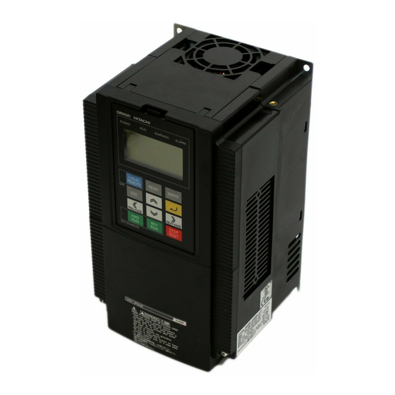
1-2 Appearance and Names of Parts 1-2 Appearance and Names of Parts When the product is unpacked, it appears as below. (Example of 3G3RX-A2150/A4150 to A2220/ A4220) Front cover Digital Operator Spacer cover Terminal block cover Open the terminal block cover and you can connect cables to the main circuit terminal block, as well as the control circuit terminal block. -
Page 23: Chapter 2 Design
Chapter 2 Design 2-1 Installation ............2-1 2-2 Wiring ..............2-6... -
Page 24: Installation
2-1 Installation 2Design 2-1 Installation WARNING Turn off the power supply and implement wiring correctly. Not doing so may result in a serious injury due to an electric shock. Wiring work must be carried out only by qualified personnel. Not doing so may result in a serious injury due to an electric shock. -
Page 25: Safety Information
2-1 Installation Safety Information Installation and Storage Do not store or use the product in the following places. •Locations subject to direct sunlight. •Locations subject to ambient temperature exceeding the specifications. •Locations subject to relative humidity exceeding the specifications. •Locations subject to condensation due to severe temperature fluctuations. •Locations subject to corrosive or flammable gases. -
Page 26: Installation Environment
2-1 Installation Installation Environment •Increased ambient temperatures will shorten the life of the Inverter. •Keep the Inverter away from heating elements (such as a braking resistor, DC reactor, etc.). If the Inverter is installed in an enclosure, keep the ambient temperature within the range of the specifications, taking dimensions and ventilation into consideration. - Page 27 2-1 Installation •To raise the carrier frequency, reduce the output current (or derate the rated current) as shown in the graph below. Voltage 200-V class 400-V class Derating at fc = 15 kHz Capacity Max. fc (kHz) Derating at fc = 15 kHz Max.
-
Page 28: Backing Plate
2-1 Installation Backing Plate Inverter with 22 kW or Lower Capacity When running cables, cut the points between the backing plate and unnecessary portions with nippers or a wire cutter, and remove. Connecting points Unnecessary portion Inverter with 30 kW or Higher Capacity For Connection Without Cable Conduit Make a cut in the rubber bushing of the backing plate with nippers or a wire cutter, and insert a ca- ble. -
Page 29: Wiring
2-2 Wiring 2-2 Wiring Standard Connection Diagram Braking resistor DC reactor (optional) (optional) P/+2 R/L1 U/T1 V/T2 S/L2 T/L3 W/T3 3-phase 200 V AC 3-phase 400 V AC Short-circuit wire To wire the control circuit power supply and main circuit power supply separately, be sure to Relay output *1 remove the J51 connector... -
Page 30: Main Circuit Terminals
2-2 Wiring Main Circuit Terminals Terminal symbol Terminal name Description R/L1, S/L2, Main power supply input Connect the input power supply. T/L3 terminal U/T1,V/T2, Inverter output terminal Connect to the 3-phase motor. W/T3 +1, P/+2 External DC reactor Remove the short-circuit bar between terminals "+1" and terminal "P/+2", and connect the optional power factor improvement DC reactor. - Page 31 2-2 Wiring Terminal Terminal name Description Specifications symbol Multi-function analog This terminal outputs a signal selected from Allowable max. current: output the "0 to 10 V DC Voltage Output" monitor 2 mA (Voltage) items: Output frequency, Output current, Output torque (with/without sign), Output voltage, Input power, Electronic thermal load rate, LAD frequency, Motor temperature, and Fin temperature.
- Page 32 2-2 Wiring Terminal Terminal name Description Specifications symbol Forward rotation When the FW signal is ON, the motor runs [Contact input ON command terminal forward. When it is OFF, the motor decelerates condition] and stops. Voltage between each input terminal and the PSC terminal: 18 V DC or more...
- Page 33 2-2 Wiring Terminal Terminal name Description Specifications symbol Relay output Select the desired functions from among 45 Contact max. functions, and allocate them. SPDT contact capacity output. MA-MC By factory default, the relay output (MA, MB) 250 V AC, 2 A contact selection (C036) is set at NC contact (Resistance) between MA-MC, and NO contact between MB-...
- Page 34 2-2 Wiring * If multi-function input terminal S3 has not been connected or disconnected, or if the signal logic is not matched, the Inverter activates an emergency shutoff trip [E37. *]. After checking the cable connection and the signal logic, input the reset signal (RS). Emergency shutoff trip [ E37.
-
Page 35: Wiring The Main Circuit Terminals
2-2 Wiring *5. Once slide switch SW1 is set to [ON], allocation of multi-function input terminals S1 and S3 will not be restored, even if SW1 is reset to [OFF] afterward. Re-allocate the terminal function. Slide switch SW1 Slide lever (factory default: OFF) Wiring the Main Circuit Terminals Main Power Supply Input Terminals (R/L1, S/L2, T/L3) •... - Page 36 2-2 Wiring • In the following cases, the internal converter module may be damaged. Use caution to avoid them: Imbalance of power supply voltage is 3% or more. Power supply capacity is ten times or more than the Inverter capacity, and also 500 kVA or more. Rapid change in power supply voltage.
- Page 37 2-2 Wiring Ground Terminal (G • To prevent electric shock, be sure to ground the Inverter and the motor. • According to the Electric Apparatus Engineering Regulations, the 200-V class Inverter should be connected to the grounding electrodes under type-D grounding conditions (conventional type 3 grounding: ground resistance 100 Ω...
- Page 38 2-2 Wiring Arrangement of Main Circuit Terminals The terminal arrangement on the Inverter main circuit terminal block is shown below. Terminal arrangement Applicable model R/L1 S/L2 T/L3 U/T1 V/T2 W/T3 P/+2 CHARGE LED indicator When not using the DC reactor, keep the +1-P/+2 short-circuit bar +1-P/+2 short-circuit bar attached.
- Page 39 2-2 Wiring Terminal arrangement Applicable model CHARGE LED indicator 3G3RX-A2150 to A2185 3G3RX-A4150 to A4220 R/L1 S/L2 T/L3 P/+2 U/T1 V/T2 W/T3 Ro,To: M4 Ground terminal: M6 Others: M6 +1-P/+2 short-circuit bar When not using the DC Ground terminal with short-circuit reactor, keep the +1-P/+2 bar (shaded area) for EMC filter short-circuit bar attached.
- Page 40 2-2 Wiring Terminal arrangement Applicable model CHARGE LED indicator R/L1 S/L2 T/L3 P/+2 U/T1 V/T2 W/T3 +1-P/+2 short-circuit bar Ground terminal with 3G3RX-A2450 short-circuit bar (shaded area) When not using the DC 3G3RX-A4450 for EMC filter function switching reactor, keep the +1-P/+2 3G3RX-A4550 short-circuit bar attached.
- Page 41 2-2 Wiring Terminal arrangement Applicable model Ro To CHARGE LED indicator 3G3RX-A4750 3G3RX-A4900 3G3RX-A411K R/L1 S/L2 T/L3 P/+2 U/T1 V/T2 W/T3 3G3RX-A413K Ro,To: M4 Ground terminal: M8 +1-P/+2 short-circuit bar Others: M10 When not using the DC reactor, keep the +1-P/+2 short-circuit bar attached.
- Page 42 2-2 Wiring Recommended Cable Size, Wiring Device and Crimp Terminal For Inverter wiring, crimp terminal and terminal screw tightening torque, refer to the table below. Power cable Applicable External Motor Applicable Ground Terminal Tightening device braking resistor Crimp output Inverter R, S, T, U, V, cable screw...
- Page 43 2-2 Wiring Power cable Applicable External Motor Applicable Ground Terminal Tightening device braking resistor Crimp output Inverter R, S, T, U, V, cable screw torque between +1 terminal Earth leakage (kW) model W, +1, P/+2, size N•m and RB (mm breaker (ELB) 3G3RX- 1.25...
- Page 44 2-2 Wiring Connection for Separating Inverter Control Circuit Power Supply from Main Power Supply If the Inverter protection circuit is activated to turn off the magnetic contactor of the Inverter input power supply, the power to the Inverter control circuit is also turned off, and the alarm signal cannot be kept on.
-
Page 45: Wiring Control Circuit Terminals
2-2 Wiring Wiring Control Circuit Terminals • Terminals FC and SC are insulated from each other via the input and output signal common terminals. Do not short-circuit or ground these common terminals. Do not ground these common terminals via external equipment. (Check the external equipment ground conditions.) •... - Page 46 2-2 Wiring Selecting the Sequence Input Method (Sink/Source Logic) When external power supply is used When the Inverter's internal interface power supply is (Remove the short-circuit bar from the control used terminal block.) Short-circuit 24 V DC 24 V DC DC24V Output unit etc.
-
Page 47: Conforming To Ec Directives
Concept of Conformity EMC Directive OMRON products are the electrical devices incorporated and used in various machines or manufacturing equipment. For this reason, we make efforts to conform our products to their related EMC standards so that the machines or equipment which have incorporated our products should easily conform to the EMC standards. -
Page 49: Operation Method
Chapter 3 Operation 3-1 Operation Method ..........3-3 3-2 Test Run Procedure ......... 3-5 3-3 Test Run Operation .......... 3-6 3-4 Part Names and Descriptions of the Digital Operator ............3-9 3-5 Keys..............3-12 3-6 Parameter Transition ........3-13 3-7 Parameter List ..........3-19... -
Page 50: Operation And Adjustment
3Operation WARNING Do not change wiring and slide switches (SW1), put on or take off Digital Operator and optional devices, replace cooling fans while the input power is being supplied. Doing so may result in a serious injury due to an electric shock. Do not remove the terminal block cover during the power supply and 10 minutes after the power shutoff. - Page 51 Precautions for Use Error Retry Function •Do not come close to the machine when using the error retry function because the machine may abruptly start when stopped by an alarm. •Be sure to confirm the RUN signal is turned off before resetting the alarm because the machine may abruptly start.
-
Page 52: Operation Method
3-1 Operation Method 3-1 Operation Method This Inverter has the following operation methods that are selected by the RUN command/ frequency reference settings. The features and the requirements for each operation method are also given below: To enter the RUN command/frequency reference via the Digital Operator Operates the Inverter via the key sequence of the standard or optional Digital Operator. - Page 53 3-1 Operation Method To enter the RUN command/frequency reference in a combination of directives from the Digital Operator and the control circuit terminal block The RUN command/frequency reference sources can be selected individually from the Digital Operator as well as the control circuit terminal block.
-
Page 54: Test Run Procedure
3-2 Test Run Procedure 3-2 Test Run Procedure Reference Item Description page Installation and Mounting Install the Inverter according to the installation conditions. • Make sure that the installation conditions are met. Wiring and Connection Connect to the power supply and peripheral devices. •... -
Page 55: Test Run Operation
3-3 Test Run Operation 3-3 Test Run Operation Power On Checkpoints Before Turning On the Power •Make sure that an appropriate power supply voltage is supplied and that the power input terminals (R/L1, S/L2, and T/L3) are wired correctly. 3G3RX- A2 : 3-phase 200 to 240 V AC 3G3RX- A4 : 3-phase 380 to 480 V AC •Make sure that the motor output terminals (U/T1, V/T2, and W/T3) are connected to the motor correctly. -
Page 56: Parameter Initialization
3-3 Test Run Operation Parameter Initialization •Initialize the parameters using the following procedure. •To initialize the parameters, set parameter b084 to "02". Key sequence Display example Description k0.0 Power On Press the Mode key once, and then press the Decrement key three bk-k-k- times to display "b---". -
Page 57: Actual Load Operation
3-3 Test Run Operation No-load Operation •Start the no-load motor (i.e., not connected to the mechanical system) using the Digital Operator. Forward/Reverse Rotation via the Digital Operator Key sequence Display example Description Press and hold the Mode key for 3 seconds or more to display "d001", and then press again. -
Page 58: Part Names And Descriptions Of The Digital Operator
3-4 Part Names and Descriptions of the Digital Operator 3-4 Part Names and Descriptions of the Digital Operator Part Names and Descriptions Data display RUN command LED indicator Operation keys Name Function POWER LED indicator Lit when the power is supplied to the control circuit. ALARM LED indicator Lit when an Inverter error occurs. - Page 59 3-4 Part Names and Descriptions of the Digital Operator Name Function Increment key Changes the mode. Also, increases the set value of each function. Decrement key Changes the mode. Also, decreases the set value of each function. Display System and Key Sequence of Each Code •...
- Page 60 3-4 Part Names and Descriptions of the Digital Operator Operation Example for Basic Display (factory default: "b037 = 04") • Displays the limited basic parameters. Monitor mode : All Basic function mode : 4 parameters Extended function mode : 24 parameters •...
-
Page 61: Keys
3-5 Keys 3-5 Keys Name Description Switches between the command setting and the data setting, and between the function mode and the extended function mode. With this key, you can always change the display as follows: [Supplemental Information] To jump to "d001" from any function mode, hold down the Mode key for 3 seconds. -
Page 62: Parameter Transition
3-6 Parameter Transition 3-6 Parameter Transition Operation and sequence of code display Operation and sequence of monitor/data display Press the Increment/Decrement key to scroll through codes in the code display and to increase/decrease the number in the data display. Press either key until you see the desired code or data. For fast-forwarding, press and hold either key. Monitor Mode Press the Mode key in the code display to display its monitor value. - Page 63 3-6 Parameter Transition Operation Example for Complete Display (Default: "b037 = 00") Displays all parameters. Operation and sequence Operation and sequence of Operation and sequence of Operation and sequence of of code display monitor/data display code display monitor/data display (Monitor/Function modes) (Monitor/Function modes) (Extended function mode) (Extended function mode)
- Page 64 3-6 Parameter Transition Display System and Key Sequence of Extended Function Mode U The extended function mode U is the parameter to optionally register (or automatically record) other extended function codes, and differs in operation from other extended function modes. Operation and sequence Operation and sequence of Operation and sequence of...
- Page 65 3-6 Parameter Transition Direct Code Specification and Selection • The codes can be specified or selected by directly entering each digit of the codes or data, as well as by scrolling the codes of the monitor, basic function, and extended function modes. •...
- Page 66 3-6 Parameter Transition 3. Change the 3rd digit of the extended function code. • "0" of the 3rd digit blinks. • Press the Enter key to fix "0" of the 3rd digit as you need not change it. ak0k0k1 Press ("0"...
- Page 67 3-6 Parameter Transition 5. Change the 1st digit of the extended function code. • "1" of the 1st digit blinks. ak0k2k1 Press ("A029" is displayed). (8 times) (2 times) • "9" of the 1st digit blinks. ak0k2k9 Press ("9" is entered.) 6.
-
Page 68: Parameter List
3-7 Parameter List 3-7 Parameter List Monitor Mode (d •The default setting displays "d001" at power-on. To select the optional display, change the setting in "b038". Changes during Parameter Default operation Function name Monitor or data range Unit Page setting Normal b031 = 10 Output frequency ⎯... - Page 69 3-7 Parameter List Changes during Parameter Default operation Function name Monitor or data range Unit Page setting Normal b031 = 10 Input power ⎯ ⎯ ⎯ d014 0.0 to 999.9 monitor 0.0 to 999.9 Integrated power 1000. to 9999. ⎯ ⎯...
- Page 70 3-7 Parameter List Changes during Parameter Default operation Function name Monitor or data range Unit Page setting Normal b031 = 10 Regenerative ⎯ ⎯ ⎯ d103 braking load rate 0.0 to 100.0 monitor Electronic thermal ⎯ ⎯ ⎯ d104 0.0 to 100.0 monitor Basic Function Mode (F Changes during...
-
Page 71: Extended Function Mode
3-7 Parameter List Extended Function Mode Changes during Parameter Default operation Function name Monitor or data range Unit Page setting Normal b031 = 10 00: Digital Operator (FREQ adjuster) (Enabled when 3G3AX-OP01 is used.) 01: Terminal 02: Digital Operator (F001) Frequency reference 03: ModBus communication 4-10... - Page 72 3-7 Parameter List Changes during Parameter Default operation Function name Monitor or data range Unit Page setting Normal b031 = 10 00: Switches between FV/FI via terminal AT 01: Switches between FV/FE via terminal AT 02: Switches between FV/FREQ adjuster via terminal AT (Enabled only when 3G3AX-OP01 is used)
- Page 73 3-7 Parameter List Changes during Parameter Default operation Function name Monitor or data range Unit Page setting Normal b031 = 10 Multi-step speed 00: Binary: 16-step selection with 4 terminals ⎯ A019 4-16 selection 01: Bit: 8-step selection with 7 terminals Multi-step speed A020 0.0/Starting frequency to Max.
- Page 74 3-7 Parameter List Changes during Parameter Default operation Function name Monitor or data range Unit Page setting Normal b031 = 10 A038 Jogging frequency 0.00/Starting frequency to 9.99 6.00 00: Free running on jogging stop/ Disabled in operation 01: Deceleration stop on jogging stop/ Disabled in operation 02: DC injection braking on jogging stop/ 4-18...
- Page 75 3-7 Parameter List Changes during Parameter Default operation Function name Monitor or data range Unit Page setting Normal b031 = 10 Automatic torque A046 boost voltage 0. to 255. 100. compensation gain ⎯ * 2nd automatic A246 torque boost voltage 0.
- Page 76 3-7 Parameter List Changes during Parameter Default operation Function name Monitor or data range Unit Page setting Normal b031 = 10 A063 Jump frequency 1 0.00 Jump frequency A064 0.50 width 1 A065 Jump frequency 2 0.00 Jump frequency: 0.0 to 400.0 Jump frequency Jump frequency width: 0.0 to 10.0 A066...
- Page 77 3-7 Parameter List Changes during Parameter Default operation Function name Monitor or data range Unit Page setting Normal b031 = 10 00: Normal operation ⎯ A085 RUN mode selection 01: Energy-saving operation 02: Automatic operation 4-36 Energy-saving ⎯ A086 response/accuracy 0.0 to 100.0 50.0 adjustment...
- Page 78 3-7 Parameter List Changes during Parameter Default operation Function name Monitor or data range Unit Page setting Normal b031 = 10 A101 FI start frequency 0.00 0.00 to 99.99 100.0 to 400.0 A102 FI end frequency 0.00 A103 FI start ratio 0.
- Page 79 3-7 Parameter List Changes during Parameter Default operation Function name Monitor or data range Unit Page setting Normal b031 = 10 EL-S-curve ratio 1 A150 0. to 50. during acceleration EL-S-curve ratio 2 A151 0. to 50. during acceleration 4-39 EL-S-curve ratio 1 A152 0.
- Page 80 3-7 Parameter List Changes during Parameter Default operation Function name Monitor or data range Unit Page setting Normal b031 = 10 Electronic thermal b012 level * 2nd electronic Rated b212 0.20 × Rated current to 1.00 × Rated current thermal level current * 3rd electronic b312...
- Page 81 3-7 Parameter List Changes during Parameter Default operation Function name Monitor or data range Unit Page setting Normal b031 = 10 00: Disabled 01: Enabled in acceleration/constant speed operation Overload limit ⎯ b021 02: Enabled in constant speed operation selection 03: Enabled in acceleration/constant speed operation (Accelerates during regeneration)
- Page 82 3-7 Parameter List Changes during Parameter Default operation Function name Monitor or data range Unit Page setting Normal b031 = 10 00: Data other than b031 cannot be changed when terminal SFT is ON. 01: Data other than b031 and the specified frequency parameter cannot be changed when terminal SFT is ON.
- Page 83 3-7 Parameter List Changes during Parameter Default operation Function name Monitor or data range Unit Page setting Normal b031 = 10 00: Four-quadrant separate setting 01: Terminal switch 4-57 b040 Torque limit selection 02: Analog input -⎯ 4-59 03: Option 1 04: Option 2 Torque limit 1 0.
- Page 84 3-7 Parameter List Changes during Parameter Default operation Function name Monitor or data range Unit Page setting Normal b031 = 10 Reverse rotation 00: Disabled ⎯ b046 4-59 prevention selection 01: Enabled Selection of non-stop 00: Disabled function at 01: Enabled (deceleration stop) ⎯...
- Page 85 3-7 Parameter List Changes during Parameter Default operation Function name Monitor or data range Unit Page setting Normal b031 = 10 Set an upper limit level. Window comparator Setting range: 0 to 100 b060 100. FV upper limit level Lower limit: Lower limit level + Hysteresis width ×...
- Page 86 3-7 Parameter List Changes during Parameter Default operation Function name Monitor or data range Unit Page setting Normal b031 = 10 Integrated power Cleared with the Enter key after changing to ⎯ b078 clear Integrated power ⎯ b079 1. to 1000. display gain b082 Starting frequency...
- Page 87 3-7 Parameter List Changes during Parameter Default operation Function name Monitor or data range Unit Page setting Normal b031 = 10 b100 Free V/f frequency 1 0. to Free V/f frequency 2 b101 Free V/f voltage 1 0.0 to 800.0 b102 Free V/f frequency 2 0.
- Page 88 3-7 Parameter List Changes during Parameter Default operation Function name Monitor or data range Unit Page setting Normal b031 = 10 Brake control 00: Disabled ⎯ b120 selection 01: Enabled Brake wait time for b121 0.00 to 5.00 0.00 release Brake wait time for b122 0.00 to 5.00...
- Page 89 3-7 Parameter List Changes during Parameter Default operation Function name Monitor or data range Unit Page setting Normal b031 = 10 01: RV (reverse) 02: CF1 (multi-step speed setting binary 1) 03: CF2 (multi-step speed setting binary 2) Multi-function input 1 04: CF3 (multi-step speed setting binary 3) C001 selection...
- Page 90 3-7 Parameter List Changes during Parameter Default operation Function name Monitor or data range Unit Page setting Normal b031 = 10 Multi-function input 1 C011 operation selection Multi-function input 2 C012 operation selection Multi-function input 3 C013 operation selection Multi-function input 4 C014 operation selection Multi-function input 5...
- Page 91 3-7 Parameter List Changes during Parameter Default operation Function name Monitor or data range Unit Page setting Normal b031 = 10 00: RUN (signal during RUN) 01: FA1 (constant speed arrival signal) 02: FA2 (over set frequency arrival signal) Multi-function output 03: OL (overload warning) C021 terminal...
- Page 92 3-7 Parameter List Changes during Parameter Default operation Function name Monitor or data range Unit Page setting Normal b031 = 10 00: Output frequency 01: Output current 02: Output torque 03: Digital output frequency 04: Output voltage 05: Input voltage 4-106 ⎯...
- Page 93 3-7 Parameter List Changes during Parameter Default operation Function name Monitor or data range Unit Page setting Normal b031 = 10 Multi-function output C031 terminal P1 contact selection Multi-function output C032 terminal P2 contact selection Multi-function output C033 terminal P3 contact 00: NO contact at MA;...
- Page 94 3-7 Parameter List Changes during Parameter Default operation Function name Monitor or data range Unit Page setting Normal b031 = 10 Overtorque level C055 (Forward power 100. running) Overtorque level C056 (Reverse 100. regeneration) 0. to 200. (0.4 to 55 kW) 4-97 0.
- Page 95 3-7 Parameter List Changes during Parameter Default operation Function name Monitor or data range Unit Page setting Normal b031 = 10 02: Loop-back test Communication 03: 2400 bps ⎯ C071 speed selection 04: 4800 bps (Baud rate selection) 05: 9600 bps 06: 19200 bps Communication ⎯...
- Page 96 3-7 Parameter List Changes during Parameter Default operation Function name Monitor or data range Unit Page setting Normal b031 = 10 00: Do not store the frequency data ⎯ C101 UP/DWN selection 4-88 01: Store the frequency data 00: Trip reset at power-on 01: Trip reset when the power is OFF 4-85 ⎯...
- Page 97 3-7 Parameter List Changes during Parameter Default operation Function name Monitor or data range Unit Page setting Normal b031 = 10 C130 Output P1 ON delay 0.0 to 100.0 C131 Output P1 OFF delay 0.0 to 100.0 C132 Output P2 ON delay 0.0 to 100.0 C133 Output P2 OFF delay 0.0 to 100.0 C134 Output P3 ON delay...
- Page 98 3-7 Parameter List Changes during Parameter Default operation Function name Monitor or data range Unit Page setting Normal b031 = 10 Logic output signal 4 Same as options for C021 to C026 C152 selection 2 (excluding LOG1 to LOG6) 00: AND Logic output signal 4 C153 01: OR...
- Page 99 3-7 Parameter List Changes during Parameter Default operation Function name Monitor or data range Unit Page setting Normal b031 = 10 00: Disabled ⎯ H001 Auto-tuning selection 01: Not rotate 4-109 02: Rotate Motor parameter 00: Standard motor parameter H002 4-109 selection 01: Auto-tuning parameter...
- Page 100 3-7 Parameter List Changes during Parameter Default operation Function name Monitor or data range Unit Page setting Normal b031 = 10 Stabilization H006 100. parameter * 2nd stabilization ⎯ H206 0. to 255. 100. 4-117 parameter * 3rd stabilization H306 100.
- Page 101 3-7 Parameter List Changes during Parameter Default operation Function name Monitor or data range Unit Page setting Normal b031 = 10 Depends Motor parameter R1 on the H030 (auto-tuning data) motor capacity. 0.001 to 9.999 Ω 10.00 to 65.53 Depends * 2nd motor on the H230...
- Page 102 3-7 Parameter List Changes during Parameter Default operation Function name Monitor or data range Unit Page setting Normal b031 = 10 H050 PI proportional gain 100.0 0.0 to 999.9 ⎯ * 2nd PI proportional 1000. H250 100.0 gain H051 PI integral gain 100.0 0.0 to 999.9 4-87...
- Page 103 3-7 Parameter List Changes during Parameter Default operation Function name Monitor or data range Unit Page setting Normal b031 = 10 Operation selection 00: Trip ⎯ P001 at option 1 error 01: Continues operation 4-108 Operation selection 00: Trip ⎯ P002 at option 2 error 01: Continues operation...
- Page 104 3-7 Parameter List Changes during Parameter Default operation Function name Monitor or data range Unit Page setting Normal b031 = 10 Position ready range 0. to 9999. 4-122 P017 Pulse setting 1000(10000) 4-129 Position ready delay 4-122 P018 0.00 to 9.99 0.00 time setting 4-129...
- Page 105 3-7 Parameter List Changes during Parameter Default operation Function name Monitor or data range Unit Page setting Normal b031 = 10 00: None ⎯ P036 Torque bias mode 01: Digital Operator 02: Terminal FE 4-121 -200. to +200. (0.4 to 55 kW) P037 Torque bias value 4-122...
- Page 106 3-7 Parameter List Changes during Parameter Default operation Function name Monitor or data range Unit Page setting Normal b031 = 10 Position range specification (reverse side) to Multi-step position P060 Position range specification (forward command 0 side)(Displays MSB 4 digits including "-") Position range specification (reverse side) to Multi-step position P061...
- Page 107 3-7 Parameter List Changes during Parameter Default operation Function name Monitor or data range Unit Page setting Normal b031 = 10 Low-speed zero P070 0.00 to 10.00 0.00 return frequency High-speed zero 0.00 to 99.99 P071 0.00 return frequency 100.0 to Maximum frequency 4-131 Position range 0 to 268435455 (at P012 = 02)
- Page 109 Chapter 4 Functions 4-1 Monitor Mode............ 4-1 4-2 Function Mode..........4-8 4-3 Functions When Option PG Board (3G3AX-PG01) Is Used ..............4-118 4-4 Communication Function........ 4-139...
-
Page 110: Monitor Mode
4-1 Monitor Mode 4Functions 4-1 Monitor Mode Output Frequency Monitor [d001] Displays the output frequency of the Inverter. During stop, "0.00" is displayed. The data LED indicator "Hz" lights up while the d001 setting is displayed. (Display) 0.00 to 99.99 : Displays in increments of 0.01 Hz. - Page 111 4-1 Monitor Mode Multi-function Input Monitor [d005] •The LED lighting position indicates the input status of the multi-function input terminals. •The item that the built-in CPU recognizes to be "significant" is indicated as being ON. This does not depend on the NO/NC contact setting. (Example) FW, Multi-function input terminals S7, S2, S1: ON Multi-function input terminals S8, S6, S5, S4, S3: OFF...
- Page 112 4-1 Monitor Mode Note: When the frequency reference is set using the Digital Operator, the output frequency can be changed with the Increment/Decrement key during operation only. The frequency setting changed with this monitor will be reflected in frequency reference F001. Pressing the Enter key overwrites the currently selected frequency reference.
- Page 113 4-1 Monitor Mode Output Voltage Monitor [d013] Displays the output voltage of the Inverter. The data LED indicator "V" lights up while the d013 setting is displayed. (Display) 0.0 to 600.0: Displays in increments of 0.1 V. Input Power Monitor [d014] Displays the input power (instantaneous value) of the Inverter.
- Page 114 4-1 Monitor Mode Power ON Time Monitor [d017] Displays the total power ON time of the Inverter. (Display) 0. to 9999. : Displays in increments of 1 hour. 1000 to 9999 : Displays in increments of 10 hours. 100 to ⎡999 : Displays in increments of 1000 hours.
- Page 115 4-1 Monitor Mode Position Command Monitor (Absolute Position Control Mode) [d029] You can monitor a position command in absolute position control mode. Note: This monitor is enabled only when V2 control mode selection P012 is set to "02" or "03" in sensor vector control mode.
- Page 116 4-1 Monitor Mode Warning Monitor [d090] •If the set data is inconsistent with other data, a warning code is displayed. •While this warning remains in effect, the PROGRAM LED indicator (PRG) stays lit until forced to rewrite or correct the data. •For details on the Warning display, refer to "5-2 Warning Function".
-
Page 117: Function Mode
4-2 Function Mode 4-2 Function Mode <Group F: Basic Function Parameters> Output Frequency Setting/Monitor •Set the Inverter output frequency. •With frequency reference selection A001 set to 02, you can set the output frequency with F001. For other methods, refer to the [A001] section in "Frequency Reference Selection" (page 4-10). (If A001 is set other than to "02", F001 functions as the frequency reference monitor.) •If a frequency is set in F001, the same value is automatically set in multi-step speed reference 0 (A020). - Page 118 4-2 Function Mode Parameter No. Function name Data Default setting Unit 00: Input via the Digital Operator Acceleration/deceleration ⎯ P031 01: Input via option 1 time input type 02: Input via option 2 Related functions A004, A204, A304, P031, C001 to C008 * To switch to 2nd/3rd acceleration time 1 or 2nd/3rd deceleration time 1, allocate 08 (SET)/17 (SET3) to the desired multi-function input and then turn it on.
-
Page 119: Frequency Reference Selection
4-2 Function Mode Operator Rotation Direction Selection •Select the rotation direction applied to the RUN command via the Digital Operator. •This is disabled at terminals. Parameter No. Function name Data Default setting Unit Operator rotation direction 00: Forward ⎯ F004 selection 01: Reverse <Group A: Standard Function Parameters>... -
Page 120: Run Command Selection
4-2 Function Mode RUN Command Selection Select the method for using the RUN/STOP command. Parameter No. Function name Data Default setting Unit 01: Terminal 02: Digital Operator (F001) RUN command ⎯ A002 03: ModBus communication selection 04: Option 1 05: Option 2 Related functions F004, C001 to C008, C019 Data... -
Page 121: Maximum Frequency
4-2 Function Mode Maximum Frequency •Set the maximum value of the output frequency. •The value set here is the maximum value (e.g.,10 V in the range from 0 to 10 V) of the external analog input (frequency reference). •The maximum Inverter output voltage from base to maximum frequencies is the voltage set in AVR voltage selection A082. - Page 122 4-2 Function Mode Parameter No. Function name Data Default setting Unit 00: FE only 01: Auxiliary frequency reference of FV and FI (not reversible) ⎯ A006 FE selection 02: Auxiliary frequency reference of FV and FI (reversible) 03: FE disabled Related functions A005, A006, C001 to C008 •The frequency reference and reversibility depend on whether "16"...
- Page 123 4-2 Function Mode (Example 1) Not reversible (Example 2) Reversible Main frequency Main frequency reference reference FI or FV terminal O FI or FV terminal O Auxiliary Auxiliary frequency frequency reference reference FE terminal FE terminal Real frequency Real frequency Forward Forward reference...
- Page 124 4-2 Function Mode (Example 1) A015/A105: 00 (Example 2) A015/A105: 01 Max. Max. frequency frequency A012/A102 A012/A102 A011/A101 A011/A101 A013/A103 A014/A104 100% A013/A103 A014/A104 100% Analog input Analog input (10 V/20 mA) (0/OI) (10 V/20 mA) (0/OI) (0 V/0 mA) (0 V/0 mA) Adjusting the FE-FC Terminal Default...
- Page 125 4-2 Function Mode FV, FE, FI Sampling •You can set the built-in filter applied to frequency setting signals of the external voltage/current input. Parameter No. Function name Data Default setting Unit A016 FV, FE, FI sampling 1. to 30./31. Time Related functions A011 to A016, C001 to C008 •Helps remove noise in the frequency setting circuit.
-
Page 126: Binary Operation
4-2 Function Mode Binary Operation •By allocating 02 to 05 (CF1 to CF4) to any of multi-function inputs 1 to 8 (C001 to C008), you can select from multi-step speeds 0 to 15. •Use A021 to A035 (multi-step speeds 1 to 15) to set frequencies for speeds 1 to 15. •When the Digital Operator is selected as the frequency reference, speed 0 is set with A020/A220/ A320 or F001 (refer to page 4-8). -
Page 127: Bit Operation
4-2 Function Mode Bit Operation •By allocating 32 to 38 (SF1 to SF7) to any of multi-function inputs selection 1 to 8 (C001 to C008), you can select from multi-step speeds 0 to 7. •For SF1 to SF7 frequency settings, set multi-step speeds 1 to 7 (A021 to A027). Frequency from the Multi-step speeds Digital Operator or... -
Page 128: Torque Boost
4-2 Function Mode Jogging Stop Selection Note: To perform the jogging operation, turn on the JG terminal before the FW or RV terminal. (Do the same if the RUN command source is set to the Digital Operator.) (Example 1) (Example 2) Deceleration Normal Jogging operation... -
Page 129: Manual Torque Boost
4-2 Function Mode Parameter No. Function name Data Default setting Unit Automatic torque boost A046 voltage compensation gain 0. to 255. 100. 2nd automatic torque boost A246 voltage compensation gain Automatic torque boost A047 slip compensation gain 0. to 255. 100. -
Page 130: Automatic Torque Boost
4-2 Function Mode Automatic Torque Boost •If the automatic torque boost is selected in the torque boost selection (A041/A241: 01), it operates to adjust the output frequency and voltage automatically, depending on the load level. (In actual control, the automatic torque boost is used along with the manual torque boost.) •To select the automatic torque boost, set motor capacity selection H003/H203 and motor pole number selection H004/H204 correctly according to your motor. -
Page 131: Constant Torque Characteristics (Vc)
4-2 Function Mode Constant Torque Characteristics (VC) Output voltage is proportional to output frequency. While proportional from 0 Hz to base frequency, the output voltage is constant from base to maximum frequencies. Output voltage (100%) Output frequency (Hz) Base frequency Max. - Page 132 4-2 Function Mode •If the free V/f setting is enabled, the functions of torque boost A041/A241, base frequency A003/ A203/A303, and maximum frequency A004/A204/A304 are disabled. (Free V/f frequency 7 is regarded as the maximum frequency.) Parameter No. Function name Data Description Default setting...
-
Page 133: Output Voltage Gain
4-2 Function Mode Output Voltage Gain •Changes the Inverter output voltage, based on the voltage selected in AVR voltage selection A082 as 100%. •You can avoid motor hunting by reducing the output voltage gain. Parameter No. Function name Data Default setting Unit A045 Output voltage gain... -
Page 134: External Dc Injection Braking
4-2 Function Mode Parameter No. Function name Data Default setting Unit 0.5 to 15.0 (0.4 to 55 kW) DC injection braking A059 carrier frequency 0.5 to 10.0 (75 to 132 kW) Related functions C001 to C008 DC Injection Braking Carrier Frequency You can set a DC injection braking carrier frequency in A059. - Page 135 4-2 Function Mode (a) Edge operation (A056: 00) (b) Level operation (A056: 01) (Example 2-a) (Example 2-b) Output Output frequency frequency A055 (Example 3-a) (Example 3-b) Free running Output Output Free running frequency frequency A053 A053 A055 Internal DC Injection Braking (A051: 01) •DC injection braking is applied without terminal operation at start/stop of the Inverter.
- Page 136 4-2 Function Mode (a) Edge operation (b) Level operation (i) During startup (example 4-a) (ii) During startup (example 4-b) Output frequency Output frequency A057 A057 A058 A058 (ii) During stop (example 5-a) (ii) During stop (example 5-b) Free running Free running Output frequency Output frequency A053...
-
Page 137: Frequency Limit
4-2 Function Mode •If the RUN command is turned on with the frequency reference established (or a value larger than the A052 setting is input), the initial operation is set to normal output. (Example 7-a) (Example 7-b) command command A052 A052 Frequency Frequency... - Page 138 4-2 Function Mode •Make sure that the upper and lower limiter settings do not exceed the maximum frequency (A004/ A204/A304). •Make sure that the output frequency (F001) and multi-step speeds 1 to 15 (A021 to A035) are not lower than the lower limit setting and not higher than the upper limit setting. •Neither limit works if set to 0 Hz.
-
Page 139: Frequency Jump Function
4-2 Function Mode Frequency Jump Function •The frequency jump function helps avoid resonant points of loaded machines. Parameter No. Function name Data Default setting Unit A063 Jump frequency 1 A065 Jump frequency 2 0.0 to 400.0 A067 Jump frequency 3 A064 Jump frequency width 1 A066... -
Page 140: Pid Function
4-2 Function Mode PID Function •This function enables process control of such elements as flow rate, air volume, and pressure. Parameter No. Function name Data Default setting Unit 00: Disabled ⎯ A071 PID selection 01: Enabled 02: Reverse output enabled ⎯... - Page 141 4-2 Function Mode PID Operation P Operation •Operation where the control volume is proportional to the target value Step transition Ramp transition Target value Large Large A072 A072 Control volume Small Small I Operation •Operation where the control volume increases linearly according to time Target value Small Small...
- Page 142 4-2 Function Mode <ASCII (C078 = 00)> Transfer data using "command 01". To transfer feedback data, set the most significant byte of frequency data to "1". (Example) To send 5 Hz: → "000500" Transmission data is "set value × 100" and expressed in 6 bytes →...
- Page 143 4-2 Function Mode PID Output Limit Function •This function limits PID output within a variable range relative to the target value. •To use this function, set PID output limit function A078. The output frequency will be limited within a range of "target value ± (A078)", with the maximum frequency defined as 100%. •With A078 set to 0.0, this function is disabled.
-
Page 144: Avr Function
4-2 Function Mode C052 (OFF level) PID feedback C053 (ON level) Time PID Feedback Value Monitor •You can monitor the PID feedback value. •The monitor value is displayed as the product of the feedback value and PID scale A075. "Monitor display" = "Feedback value (%)" × "A075 setting" PID Integral Reset •Clears the integral value of PID operation. -
Page 145: Automatic Energy-Saving Operation Function
4-2 Function Mode Automatic Energy-saving Operation Function •This function automatically minimizes the Inverter output power during constant speed operation, and is suitable for load with reduced torque characteristics (e.g. fan, pump). Parameter No. Function name Data Default setting Unit 00: Normal operation ⎯... - Page 146 4-2 Function Mode Note 3: Acceleration/deceleration time varies depending on fluctuations in current value, even with the same motor. Note 4: The automatic optimum acceleration/deceleration setting is enabled only during V/f control. When sensorless vector control is selected, the Inverter performs normal operation. Note 5: If the jogging operation is performed when the automatic operation is selected, the Inverter performs automatic acceleration, which is different from normal jogging operation.
-
Page 147: Acceleration/Deceleration Pattern
4-2 Function Mode •Select an acceleration/deceleration time switching method from the following three: Switching via a multi-function input Automatic switching at a specified frequency Automatic switching only when switching between forward/reverse If the 3rd control function is selected, however, switching by the 2-step acceleration/deceleration frequency is disabled. - Page 148 4-2 Function Mode Parameter No. Function name Data Default setting Unit A131 Acceleration curve parameter 01 (small curve) to ⎯ 10 (large curve) A132 Deceleration curve parameter EL-S-curve ratio 1 during A150 acceleration 0 to 50 EL-S-curve ratio 2 during A151 acceleration EL-S-curve ratio 1 during...
- Page 149 4-2 Function Mode Pattern Curve Parameter (Curve Factor) •Determine a curve factor with reference to the figures below. Output frequency (Hz) Output frequency (Hz) Output frequency (Hz) Target Target Target frequency frequency frequency (100%) (100%) (100%) 99.6 96.9 10 02 93.8 82.4 87.5...
-
Page 150: Frequency Addition Function
4-2 Function Mode Operation Frequency Function •Two systems of frequency reference operation results are available for the frequency reference and PID feedback value. Parameter No. Function name Data Default setting Unit 00: Digital Operator (F001) (A020/A220/A320) Operation frequency ⎯ A141 01: Digital Operator (FREQ adjuster) input A setting (Enabled when 3G3AX-OP01 is... - Page 151 4-2 Function Mode <Group B: Detailed Function Parameters> Momentary Power Interruption/Trip Retry (Restart) Restart During Momentary Power Interruption •You can set whether the Inverter trips or retries (restarts) when a momentary power interruption or undervoltage occurs. •If the retry function is selected in retry selection b001, the Inverter retries for the number of times set in b005 (for momentary power interruption) or b009 (for undervoltage), and trips on the next time.
- Page 152 4-2 Function Mode Parameter No. Function name Data Default setting Unit Overvoltage/ 1 to 3 b010 overcurrent retry Select the number of retry times in the event of Time time overvoltage/overcurrent 0.3 to 100. b011 Trip retry wait time Time before restart 0.20 ×...
- Page 153 4-2 Function Mode (Example 4) Motor frequency (rpm) < b007 (Example 3) Motor frequency (rpm) > b007 Power supply Power supply Inverter output Inverter output Free running Free running b007 b007 Motor frequency Motor frequency (rpm) (rpm) Frequency matching start 0-Hz start Alarm Output for Momentary Power Interruption/Undervoltage During Stop •Use b004 to select whether to enable an alarm output in case of momentary power interruption or...
- Page 154 4-2 Function Mode (Example 8) b004: 00 Inverter is stopped Inverter is running Power supply Power supply RUN command RUN command Inverter output Inverter output Alarm Alarm Signal during momentary Signal during momentary power interruption (IP) power interruption (IP) Inverter is stopped Inverter is running (Example 9) b004: 01 Power supply...
-
Page 155: Electronic Thermal Function
4-2 Function Mode •The Digital Operator displays until restart, after output is shut off. okokoko b028 Output current Decelerates according to b029 Inverter output frequency Frequency selected in b030 Motor rotation speed b003 Input Power Supply Phase Loss Protection Function Selection •This function outputs an alarm when the Inverter's input power supply has phase loss. - Page 156 4-2 Function Mode Parameter No. Function name Data Default setting Unit Free setting, electronic thermal b015 frequency 1 Free setting, electronic thermal b017 0. to 400. frequency 2 Free setting, electronic thermal b019 frequency 3 Free setting, electronic thermal b016 current 1 Free setting, electronic thermal b018...
- Page 157 4-2 Function Mode Reduced Torque Characteristics Multiplied by the time limit characteristics set in b012/b212/b312 for each frequency. (Example) 3G3RX-A2150 (Rated current: 64 A), b012 = 64 Base frequency = 60 Hz Output frequency = 20 Hz Torque Trip time (s) x1.0 x0.8 x0.6...
-
Page 158: Thermal Warning
4-2 Function Mode Thermal Warning •This function outputs an alarm signal before electronic thermal overheat protection is activated. The warning level can be set in C061. •Allocate 13 (THM) to any of multi-function output terminals P1 to P5 (C021 to C025) or the relay output terminal (C026). - Page 159 4-2 Function Mode • If "sensorless vector control", "0-Hz sensorless vector control", or "sensor vector control" is selected as the control method (V/f characteristics) (refer to "Control Method (V/f Characteristics)" (page 4- 21)), and "03" is selected for b021/b024, the frequency increases when a current exceeding the overload limit level flows during regenerative operation.
-
Page 160: Overcurrent Suppression Function
4-2 Function Mode Overcurrent Suppression Function •This function suppresses overcurrent caused by a steep current rise in rapid acceleration. •You can set whether to enable or disable this function with b027. Parameter No. Function name Data Default setting Unit Overcurrent suppression 00: Disabled ⎯... -
Page 161: Rotation Direction Limit Selection
4-2 Function Mode RUN Time/Power ON Time Exceeded •If the total RUN time of the Inverter exceeds the time set in ON time setting b034, a RUN/Power ON 'time exceeded' (RNT/ONT) signal is output. Parameter No. Function name Data Default setting Unit 0.: Does not operate. -
Page 162: Reduced Voltage Startup Selection
4-2 Function Mode Reduced Voltage Startup Selection •Slowly increases voltage during motor startup. •To increase torque during startup, reduce the set value of reduced voltage startup selection b036. Note that if the value is too small, the motor starts in full-voltage starting mode, possibly resulting in an overcurrent trip. - Page 163 4-2 Function Mode Individual Display of Functions •If a specific function is not selected, its relevant parameter is not displayed. •For details on the display requirements, refer to the following table. Display requirements Parameters displayed when the requirements are met A005, A006, A011 to A016, A101, A102 A001 = 01 A111 to A114, C081 to C083, C121 to C123...
- Page 164 4-2 Function Mode Display requirements Parameters displayed when the requirements are met Any of C001 to C008 = 08, and A246, A247 A041 = 01 Any of C001 to C008 = 08, and A241, A242, A243 A244 = 00, 01 Any of C001 to C008 = 08, and H202, H205, H250, H251, H252 A244 = 03, 04...
-
Page 165: Basic Display
4-2 Function Mode Basic Display •Displays basic parameters. (Factory default) •Below are the parameters displayed when this function is enabled. Data Function name Data Function name d001 to d104 Monitor display A045 Output voltage gain F001 Output frequency setting/monitor A085 RUN mode selection F002 Acceleration time 1... -
Page 166: User Parameter Automatic Setting Function
4-2 Function Mode User Parameter Automatic Setting Function •When user parameter automatic setting function b039 is set to "01" (enabled), the parameters subjected to a data change are automatically stored in sequence (from U001 to U012). This data can be used as changed data. •The screen information is stored when the Enter key is pressed. - Page 167 4-2 Function Mode •You can select any of the following four torque limit functions from torque limit selection b040. <Four-quadrant separate setting mode> Sets torque limits 1 to 4 (b041 to b044) for four quadrants (forward power running, regeneration, reverse power running, and regeneration). <Terminal switching mode>...
-
Page 168: Reverse Rotation Prevention Function
4-2 Function Mode Reverse Rotation Prevention Function •This function is enabled when "03" (sensorless vector control), "04" (0-Hz sensorless vector control), or "05" (sensor vector control) is selected in control method A044/A244. •Because of the Inverter's control characteristics, the Inverter may output a rotation signal in the direction opposite to that of the RUN command (e.g. - Page 169 4-2 Function Mode Parameter No. Function name Data Default setting Unit 40: Torque limit enabled Multi-function inputs ⎯ ⎯ C001 to C008 41: Torque limit switching 1 1 to 8 selection 42: Torque limit switching 2 Momentary Power Interruption Non-stop Function •After the power is shut off during operation, this function decelerates the Inverter to a stop while keeping the voltage below the overvoltage level.
- Page 170 4-2 Function Mode Momentary Power Interruption Non-stop Deceleration Stop (b050 = 01) •After the power is shut off during operation, this function decelerates the Inverter to a stop while keeping the voltage below the momentary power interruption non-stop deceleration level (b052). •To use this function, remove the J51 connector cable connected between terminals Ro and To, and connect the cable from main terminal P to Ro, and from N to To.
- Page 171 4-2 Function Mode Momentary Power Interruption Non-stop DC Voltage Constant Control (b050 = 02: without recovery, b050 = 03: with recovery) •If a momentary power interruption or main circuit DC voltage drop occurs during operation, the Inverter decelerates while keeping the main circuit DC voltage at the value set in momentary power interruption non-stop target voltage (OV-LADSTOP level) b052.
- Page 172 4-2 Function Mode (Example 1) (Example 2) Main circuit DC voltage Main circuit P-N voltage Main circuit P-N voltage at power recovery Vpn (V) Vpn (V) b052 b052 Power recovery b051 b051 Main circuit DC voltage DC voltage kept constant DC voltage kept constant Time Time...
- Page 173 4-2 Function Mode Parameter No. Function name Data Default setting Unit b061 (FV) Set a lower limit level. Setting range: 0 to 100 Upper limit: Upper limit level - Hysteresis b064 (FI) width × 2 Window comparator FV/FI/FE lower limit level Set a lower limit level.
-
Page 174: Starting Frequency
4-2 Function Mode Starting Frequency •Set the frequency for starting Inverter output when the RUN signal is turned on. Parameter No. Function name Data Default setting Unit b082 Starting frequency 0.10 to 9.99 0.50 •Use mainly to adjust the starting torque. •With starting frequency b082 set high, the starting current increases, possibly causing the current to exceed the overload limit and overcurrent protection to work to trip the Inverter. - Page 175 4-2 Function Mode Voltage 200-V class 400-V class Derating at fc = 15 kHz Capacity Max. fc (kHz) Derating at fc = 15 kHz Max. fc (kHz) (75 to 132 kW is for 10 kHz) 5.5 kW 100% 100% 7.5 kW 100% 100% 11 kW...
- Page 176 4-2 Function Mode Initialization Method After setting the above parameter, use the following method to initialize. (1) Press the STOP/RESET key with the Mode and Decrement keys pressed simultaneously. • Release the STOP/RESET key when the display blinks. (The display changes as shown below.) 8k8k8k8 •...
-
Page 177: Stop Key Selection
4-2 Function Mode STOP Key Selection •When "control circuit terminal block" is selected for the RUN command, you can set whether the STOP/RESET key on the Digital Operator is used to activate the STOP command and trip reset operation. •This setting is enabled when any item other than "02" (Digital Operator) is selected in RUN command selection A002. - Page 178 4-2 Function Mode Free-run Stop Selection •Activating the free-run stop (FRS) function shuts off the Inverter output, letting the motor go into free-run status. Parameter No. Function name Data Default setting Unit 00: 0-Hz start (example 1) ⎯ b088 Free-run stop selection 01: Frequency matching start (example 2) 02: Frequency pull-in restart (example 3) b003...
- Page 179 4-2 Function Mode (Example 1) 0-Hz start (Example 2): Frequency matching start Free running 0-Hz start Free running Motor Motor b003 Frequency matching start • The Inverter starts running at 0 Hz regardless of the • When the FRS terminal is turned off and the retry wait motor rpm.
-
Page 180: Automatic Carrier Frequency Reduction Function
4-2 Function Mode Automatic Carrier Frequency Reduction Function •This function automatically reduces carrier frequency according to an increase in output current. •This function is enabled when automatic carrier frequency reduction selection b089 is set to "01". Parameter No. Function name Data Default setting Unit... -
Page 181: Regenerative Braking Function
4-2 Function Mode Regenerative Braking Function •This function applies to the Inverter models with a built-in regenerative braking circuit (3G3RX-A2220/A4220 or lower models). •With the built-in regenerative braking circuit, this function allows an external braking resistor to consume the motor's regeneration energy as heat. This function is useful for a system in which the motor works as a generator when it is rapidly decelerated. -
Page 182: Brake Control Function
4-2 Function Mode External Thermistor (TH) •This function enables thermal protection of the external equipment (e.g. motor) if its internal thermistor is connected to the Inverter. Parameter No. Function name Data Default setting Unit 00: Disabled 01: Enabled, Positive temperature ⎯... - Page 183 4-2 Function Mode (6) If the brake confirmation signal (BOK) is allocated to a multi-function input (when "44" is set in any of C001 to C008), the Inverter waits for the brake confirmation signal to be turned off for the period set in brake confirmation wait time b124 without decelerating, after the brake release signal is turned off.
- Page 184 4-2 Function Mode Parameters Required for Brake Control Function Parameter No. Function name Data Default setting Unit 00: Disabled ⎯ b120 Brake control selection 01: Enabled 0.00 to 5.00: Brake wait time for Set a time required for the output current to b121 0.00 release...
- Page 185 4-2 Function Mode Overvoltage Protection Function During Deceleration •This function helps avoid an overvoltage trip due to regenerative energy from the motor during deceleration. •You can set whether to enable or disable this function with overvoltage protection function selection during deceleration b130. •If overvoltage protection function selection b130 is set to "01"...
- Page 186 4-2 Function Mode Note 2: Even if this function is enabled, an overvoltage trip may occur depending on the deceleration rate and load condition. Note 3: When using this function, the Inverter may reduce frequency depending on the moment of inertia of motor load, and takes a long time to stop.
- Page 187 4-2 Function Mode Parameter Data Function name Reference item Page : Soft lock Soft lock 4-51 : Analog input switching External analog input 4-12 SET3 : 3rd control 2nd/3rd control function 4-80 : Reset Reset 4-85 : 3-wire start : 3-wire stop 3-wire input function 4-86 : 3-wire forward/reverse...
- Page 188 4-2 Function Mode Parameter Data Function name Reference item Page FOC : Preliminary excitation Preliminary excitation function 4-116 Not used Not used Not used Not used ⎯ Not used Not used Not used Not used AHD : Analog command held Analog command held 4-91 C001 to...
- Page 189 4-2 Function Mode 2nd/3rd Control Function •You can switch between three motors to control the Inverter by allocating 08 (SET)/17 (SET3) to any of multi-function inputs 1 to 8 (C001 to C008) and then turning on/off the SET/SET3 terminal. Parameter No. Function name Data Default setting...
- Page 190 4-2 Function Mode *1. When the emergency shutoff function is enabled (SW1 = ON), C001 and C003 are forced to change to "18" (RS) and "64" (EMR), respectively. (You cannot intentionally set "64".) If SW1 is turned on and then off, C003 is set to "no" (no allocation). The functions switchable via the SET/SET3 terminal are: F002/F202/F302 * : 1st/2nd/3rd...
-
Page 191: External Trip
4-2 Function Mode External Trip •This function trips the Inverter via an error (trip) signal from a peripheral system. To use this function, allocate "12" (EXT) to any of multi-function inputs 1 to 8 (C001 to C008). Data Symbol Function name Status Description Sets the motor to free-run status by shutting off output. -
Page 192: Commercial Switching
4-2 Function Mode •The following shows how the power recovery restart prevention function works. (Example 1) (Example 2) (Example 3) Power Power Power supply supply supply Alarm Alarm Alarm Output Output Output frequency frequency frequency Commercial Switching •You can use this function to drive a system with large moment of inertia during acceleration and deceleration by using the Inverter, and during constant speed by using a commercial power supply. - Page 193 4-2 Function Mode Examples of connections and timing of commercial switching operation THRY ELBC Motor Timing example of switching from Timing example of switching from Inverter to commercial power commercial power to Inverter Interlock time of MC2 and MC3 (0.5 to 1 s) Retry wait time b003 Inverter output 0.5 to 1 s...
- Page 194 4-2 Function Mode Reset •This function resets an Inverter trip. Parameter No. Function name Data Default setting Unit 0.3 to 100.: (Refer to "Momentary Power Interruption/ b003 Retry wait time Trip Retry (Restart)" (page 4-42).) Time from reset to restart Frequency matching 0.00 to 400.0: b007...
-
Page 195: Wire Input Function
4-2 Function Mode (Example 3) If "01" (frequency matching start) is selected in reset frequency matching selection C103, frequency matching start is also enabled when the power is turned on again. When C103 = 00 (0-Hz start), the retry wait time (b003) is ignored. Even if "frequency matching start" is selected, however, the Inverter may start at 0 Hz if: •... -
Page 196: Control Gain Switching Function
4-2 Function Mode Data Symbol Function name Status Description Available input terminals C001 to C008 Required settings A002 = 01 •Set RUN command selection A002 to 01 (control circuit terminal block). •The following operations become possible when 20 (STA), 21 (STP), and 22 (F/R) are allocated to any of multi-function inputs 1 to 8 (C001 to C008). - Page 197 4-2 Function Mode Parameter No. Function name Data Default setting Unit 0. to 9999. (ms): H073 Gain switching time 100. Taper time during gain switching •If control gain switching is selected in the multi-function input selection, turning off the signal selects the gain setting of H050, H250, H051, H251, H052, or H252.
- Page 198 4-2 Function Mode RUN command (FW, RV) Acceleration/Deceleration does not occur if the UP and DWN terminals turn on simultaneously. Output frequency Forced Operator Function •This function forcibly enables operation via the Digital Operator by turning on/off the multi-function terminal if the frequency reference/RUN command sources are not set to the Digital Operator. Data Symbol Function name...
- Page 199 4-2 Function Mode •If P/PI switching is selected in the multi-function input selection, proportional integral compensation is enabled while the signal is off; proportional compensation is enabled while the signal is on. If P/PI switching is not selected in multi-function inputs 1 to 8 (C001 to C008), proportional integral compensation is enabled.
-
Page 200: Analog Command Hold Function
4-2 Function Mode Analog Command Hold Function •While the AHD terminal is turned on, the Inverter keeps external analog input results on hold. Parameter No. Function name Data Default setting Unit Multi-function inputs ⎯ ⎯ C001 to C008 65: AHD (analog command held) 1 to 8 selection •While the AHD terminal is turned on, you can use the UP/DWN function based on the reference value of the analog signal kept on hold by this function. - Page 201 4-2 Function Mode Multi-function Output Terminal Selection •You can allocate the following functions to any of multi-function output terminals P1 to P5 (C021 to C025) or the alarm relay output terminal (C026). •Multi-function output terminals P1 to P5 provide open-collector output. The alarm relay output terminal provides relay output.
- Page 202 4-2 Function Mode Data Description Reference item Page LOG1: Logic operation output 1 LOG2: Logic operation output 2 LOG3: Logic operation output 3 Logic operation function 4-99 LOG4: Logic operation output 4 LOG5: Logic operation output 5 LOG6: Logic operation output 6 WAC: Capacitor life warning signal Capacitor life warning signal 4-100...
- Page 203 4-2 Function Mode Specifications of Multi-function Output Terminals P1 to P5 •Below are the specifications of multi-function output terminals P1 to P5. Inside the Inverter Power Output C031 to C035 set values Electrical characteristics supply status Between each terminal and PC Voltage drop 4 V max.
- Page 204 4-2 Function Mode Signal During RUN •While the Inverter is running, this signal is output via multi-function output terminals P1 to P5 or the relay output terminal. •Allocate "00" (RUN) to any of multi-function output terminals P1 to P5 (C021 to C025) or the relay output terminal (C026).
- Page 205 4-2 Function Mode Constant Speed Arrival Output (01: FA1) A signal is output when the output frequency has reached the level set in the frequency setting (F001, A020, A220, and A320) or multi-step speed (A021 to A035). : 1% of the max. frequency Set frequency : 2% of the max.
- Page 206 4-2 Function Mode Overtorque (OTQ) •This function outputs a signal when detecting a motor output torque estimated value exceeding a specified level. Parameter No. Function name Data Default setting Unit Multi-function output C021 to C025 terminal selection ⎯ 07: OTQ: Overtorque signal Relay output (MA, MB) C026 function selection...
- Page 207 4-2 Function Mode 0-Hz Detection Signal •This function outputs a detection signal when the Inverter's output frequency falls below the 0-Hz detection value set in 0-Hz detection level C063. Parameter No. Function name Data Default setting Unit Multi-function output ⎯ C021 to C025 terminal selection ⎯...
- Page 208 4-2 Function Mode Multi-function output terminals With 4-bit code selected With 3-bit code selected Factor code Trip cause Factor code Trip cause Braking resistor overload ⎯ Other errors protection EEPROM error, CPU error, E08, E11 ⎯ ⎯ GA communication error, Main E23, E25 circuit error ⎯...
- Page 209 4-2 Function Mode •You can select from three types of operators (AND, OR, and XOR). Output signal 1 Output signal 2 LOGx (AND) LOGx (OR) LOGx (XOR) •The setting parameters vary depending on the logic operation output selected. Refer to the following table to set the necessary parameters. Operand 1 Operand 2 Operator...
- Page 210 4-2 Function Mode Network Error •Enabled only when ModBus-RTU is selected for RS485 communication. •If a reception timeout error occurs, this signal is output until reception of the next data. •Set a time before reception timeout in communication error timeout C077. •For details, refer to "4-4 Communication Function".
- Page 211 4-2 Function Mode Starting Contact Signal •While the Inverter is receiving the RUN command, a starting contact signal is output. •The output is enabled regardless of the setting of RUN command source selection A002. •If inputs FW and RV are simultaneously turned on, the Inverter stops. Parameter No.
- Page 212 4-2 Function Mode Light Load Detection Signal •This signal is output when output current falls below the light load detection level (C039). •In light load signal output mode C038, you can set whether this output is enabled in any operation mode, or only in constant speed operation.
-
Page 213: Forward Run Signal
4-2 Function Mode Forward Run Signal •This signal is output while the Inverter is running forward. •While the Inverter is running in reverse, or when stopped, this signal is turned off. Parameter No. Function name Data Default setting Unit Multi-function output ⎯... -
Page 214: Input Terminal Response Time
4-2 Function Mode (These trips are caused by hardware.) Error code Description E10.* CT error E11.* CPU error E14.* Grounding protection E20.* Abnormal temperature due to cooling fan stop E23.* Gate array communications error E25.* Main circuit error Multi-function Output Terminal ON Delay/OFF Delay •You can set ON/OFF delay times for each output terminal. - Page 215 4-2 Function Mode Digital MP Terminal •You can monitor the output frequency and current using the MP terminal on the control circuit terminal block. •The MP terminal provides pulse output. MP Selection •Select a signal to output from the following table. For "03"...
- Page 216 4-2 Function Mode MP Adjustment •Adjust the Inverter output gain according to the meter connected to the MP terminal. Parameter No. Function name Data Default setting Unit C105 MP gain setting 50. to 200.: Set a gain for the MP monitor. 100.
- Page 217 4-2 Function Mode *2. Below are the specifications of the output torque (signed). AM output (V) AM gain setting (C106) = 100% AM gain setting (C106) = 200% AM bias setting (C109) = 50% Torque (%) *3. When "sensor vector control" is selected (A044 = 05), the real frequency (detected frequency) is displayed. AM/AMI Adjustment •Adjust the Inverter output gain according to the meters connected to the AM and AMI terminals.
- Page 218 4-2 Function Mode •For motor parameters, the Inverter inputs data on one phase of Y-connection at 50 Hz. Parameter No. Function name Data Default setting Unit 00: Disabled ⎯ H001 Auto-tuning selection 01: Enabled (Motor does not rotate.) 02: Enabled (Motor rotates.) 00: Standard motor parameter 01: Auto-tuning parameter ⎯...
- Page 219 4-2 Function Mode •With a machine (e.g. lift, ball screw) whose motor shaft rotation is limited, the machine may be damaged if the allowable rotation limit is exceeded. In this case, set H001 to "01" (auto- tuning without motor rotation). •With a motor whose no-load current is unknown, measure the current at 50 Hz in the "V/f setting"...
- Page 220 4-2 Function Mode Online Auto-Tuning Function •Online auto-tuning compensates for changes in motor parameters resulting from a motor temperature rise or other factor, thus ensuring stable operation. •This function is applicable to 1st/2nd control, not to 3rd control. Parameter No. Function name Data Default setting...
-
Page 221: Motor Parameter Selection
4-2 Function Mode Motor Parameter Selection •Set this parameter according to your motor. •To use several motors with a single Inverter in the "VC", "special VP", or "free V/F setting" control mode, calculate the total capacity of the motors and select the closest value in the motor capacity selection. -
Page 222: Sensorless Vector Control
4-2 Function Mode *2: Convert moment of inertia J into motor shaft data. The larger the J value, the faster the response, resulting in a steep torque rise; the smaller the J value, the slower the response, resulting in a gradual torque rise. After setting the J value, adjust the response speed in speed response H005/H205. -
Page 223: Hz Sensorless Vector Control
4-2 Function Mode Note 1: Make sure that the carrier frequency (b083) is not lower than 2.1 kHz. If the carrier frequency is lower than 2.1 Hz, the Inverter does not operate normally. Note 2: To use lower rank motor size than the Inverter, set a torque limit value (b041 to b044), while keeping the value α, calculated with the following formula, at 200% or lower. - Page 224 4-2 Function Mode •If 0-Hz sensorless vector control cannot provide the desired characteristics, adjust the motor parameters depending on the phenomena, as shown in the table below. Operation Phenomenon Adjusting method Adjustment item status Speed change ratio is a Increase motor parameter R2 gradually (up to set H021/H221/H031 negative value.
-
Page 225: Torque Monitor Function
4-2 Function Mode Torque Monitor Function •This function allows you to monitor an estimated motor output torque, when "sensorless vector control", "0-Hz sensorless vector control", or "sensor vector control" is selected as the control method. Parameter No. Function name Data Default setting Unit 03: Sensorless vector... -
Page 226: Stabilization Parameter
4-2 Function Mode High-torque Multi-operation •When "sensorless vector control" or "0-Hz sensorless vector control" is selected with a single Inverter, this function controls two motors of the same type to drive a single load. •To use this function, you set the same parameters as when you select "Sensorless Vector Control" (page 4-113) or "0-Hz Sensorless Vector Control"... -
Page 227: Functions When Option Pg Board (3G3Ax-Pg01) Is Used
4-3 Functions When Option PG Board (3G3AX-PG01) Is Used 4-3 Functions When Option PG Board (3G3AX-PG01) Is Used Functions That Need 3G3AX-PG01 •Generally, the Feedback Option Board (3G3AX-PG01) is required for the following two cases: • "05" (V2: sensor vector control) is selected in V/f characteristics selection A044. •... - Page 228 4-3 Functions When Option PG Board (3G3AX-PG01) Is Used V2 Control Mode Selection Select a control method in V2 control mode selection P012. When "00" (ASR) is selected in P012, speed control mode is enabled. Select a frequency reference in frequency reference selection A001. When "01"...
- Page 229 4-3 Functions When Option PG Board (3G3AX-PG01) Is Used Sensor Vector Control (Speed Control) To use this function, set V/f characteristics selection A044 to "05" (V2), and V2 control mode selec- tion P012 to "00" (speed control). ("Sensor vector control" can be selected for 1st control only.) To use this function, make sure that the motor parameter settings are suitable for your motor.
-
Page 230: Torque Control
4-3 Functions When Option PG Board (3G3AX-PG01) Is Used Torque Bias Function This function applies bias to the torque reference generated by speed control, and is useful for ele- vating applications (e.g. elevator). Parameter No. Function name Data Default setting Unit 00: Disabled ⎯... -
Page 231: Pulse Train Position Control Mode
4-3 Functions When Option PG Board (3G3AX-PG01) Is Used Parameter No. Function name Data Default setting Unit Speed limit value in P039 0.00 to 99.99/100.0 to 400.0 0.00 torque control (forward) Speed limit value in P040 0.00 to 99.99/100.0 to 400.0 0.00 torque control (reverse) 00: Disabled... - Page 232 4-3 Functions When Option PG Board (3G3AX-PG01) Is Used Parameter No. Function name Data Default setting Unit 0. to 9999./1000 (10000): Position ready ⎯ P017 Set a value equivalent to encoder ×4 range setting multiplication. Position ready P018 0.00 to 9.99 0.00 delay time setting Electronic gear setting...
-
Page 233: Electronic Gear Function
4-3 Functions When Option PG Board (3G3AX-PG01) Is Used •Mode 1: Forward/Reverse command + Pulse train (Pulse train input) (Forward/Reverse command) Detected pulses Forward Reverse Time •Mode 2: Forward pulse train + Reverse pulse train (Forward pulse train input) (Reverse pulse train input) Detected pulses Forward... - Page 234 4-3 Functions When Option PG Board (3G3AX-PG01) Is Used Note: Below are the block diagrams of the electronic gear function. First-order lag filter Position control feedforward gain P022 1+sT Position loop gain P019 = 00 (FB) Position Speed P023 command command Electronic gear Position feedback...
- Page 235 4-3 Functions When Option PG Board (3G3AX-PG01) Is Used Example: Synchronous Operation Master Inverter Slave Inverter AP, BP SAP, SBP AN, BN SAN, SBN EAP, EBP EAP, EBP EAN, EBN EAN, EBN Main motor motor For the Inverter (master Inverter) on the main motor side, you can select either the speed control or pulse train position control mode.
- Page 236 4-3 Functions When Option PG Board (3G3AX-PG01) Is Used Configuration Example •Main motor : Number of encoder pulses = 1024 •Sub motor : Number of encoder pulses = 3000 •Main motor rpm:Sub motor rpm = 2:1 For operation under the above conditions, set the following data in the slave Inverter. Electronic gear setting position selection (P019) : 01 (REF) Electronic gear ratio numerator (P020) : 3000 Electronic gear ratio denominator (P021) : 1024 ×...
-
Page 237: Position Bias Function
4-3 Functions When Option PG Board (3G3AX-PG01) Is Used Motor Gear Ratio Setting Function This function is useful for a system with an optional encoder installed on the machine side. Set the number of actual encoder pulses in encoder pulses P011. Set a motor-to-encoder rpm ratio in motor gear ratio numerator/denominator P028/P029. -
Page 238: Speed Bias Function
4-3 Functions When Option PG Board (3G3AX-PG01) Is Used Speed Bias Function This function applies speed command bias in the pulse train position control mode. Set a bias value in frequency addition amount A145, and select a sign in frequency addition direc- tion A146. - Page 239 4-3 Functions When Option PG Board (3G3AX-PG01) Is Used RUN commands (FW/RV) ORT terminal Output frequency Orientation speed setting (P015) Position ready range setting (P017) Z pulse POK signal Position ready delay time setting (P018) Speed control Position control (1) When the RUN command is turned on with the ORT terminal turned on, the Inverter accelerates to the orientation speed (P015), and then performs constant speed operation.
-
Page 240: Absolute Position Control Mode
4-3 Functions When Option PG Board (3G3AX-PG01) Is Used Absolute Position Control Mode •To use this function, set V/f characteristics selection A044 to "05" (V2), and V2 control mode selection P012 to "02" (APR2: Absolute position control). •When "03" (high-resolution absolute position control) is selected in V2 control mode selection P012, control is based on ×4 the number of pulses used for internal operations. - Page 241 4-3 Functions When Option PG Board (3G3AX-PG01) Is Used Parameter No. Function name Data Default setting Unit Position range −268435456 to 0: When APR2 is selected −268435455 ⎯ P073 specification −1073741823 to 0: When HAPR is selected (reverse) 00: Multi-step position command 0 (P060) 01: Multi-step position command 1 (P061) 02: Multi-step position command 2 (P062) 03: Multi-step position command 3 (P063)
- Page 242 4-3 Functions When Option PG Board (3G3AX-PG01) Is Used In the absolute position control mode, the Inverter moves to the target position according to the fol- lowing parameter settings, and is then set in the position servo lock status. • Position command •...
- Page 243 4-3 Functions When Option PG Board (3G3AX-PG01) Is Used When you input a multi-step position command, you can set the wait time until the terminal input is determined. This prevents the transition status from being applied before it is determined. You can adjust the determination time in multi-step speed/position determination time C169.
-
Page 244: Zero Return Function
4-3 Functions When Option PG Board (3G3AX-PG01) Is Used Zero Return Function This function performs three types of zero return operations depending on the setting of zero return mode P068. When zero return is complete, the current position is cleared to zero. You can select the zero return direction in zero return direction selection P069. -
Page 245: Teaching Function
4-3 Functions When Option PG Board (3G3AX-PG01) Is Used Forward/Reverse Run Stop Function (FOT/ROT) With a signal from the control range limit switch, this function prevents the Inverter from running out- side the specified operation range. The torque limit is set to 10% on the forward side when the FOT terminal is turned on, and on the reverse side when the ROT terminal is turned on. - Page 246 4-3 Functions When Option PG Board (3G3AX-PG01) Is Used (4) The current position is set to the area corresponding to the position command source set in teaching selection P074. (However, the P074 setting is not stored. After the power is shut off or after reset, this parameter is indicated as "00"...
-
Page 247: Pulse Train Frequency Input
4-3 Functions When Option PG Board (3G3AX-PG01) Is Used Pulse Train Frequency Input This function allows you to use a pulse train input to the SAP-SAN terminals as frequency reference or PID feedback value in each control mode. (This function can be used in all control modes.) Set the input frequency at the maximum frequency in pulse train frequency scale P055. -
Page 248: Communication Function
4-4 Communication Function Communication Function •This function allows the Inverter to communicate with an external controller via the RS485 interface from the TM2 terminal on the Inverter's control terminal block board. Communication Specifications Item ASCII method ModBus-RTU method Note Select using Transmission speed 2400/4800/9600/19200 bps the Digital Operator. - Page 249 4-4 Communication Function <RS485 Port Specifications and Connections> For the RS485 communication function, use the TM2 terminal on the control terminal block board. Terminal Description abbreviations Transmission/Reception (+) Transmission/Reception (-) Control terminal Termination resistor enabling terminal block Termination resistor enabling terminal Control terminal block board The following wires are recommended for TM2:...
- Page 250 4-4 Communication Function Setting RS485 communication requires the following settings. Parameter No. Function name Data Default setting Unit 02: Loop-back test Communication speed 03: 2400 bps ⎯ C071 selection 04: 4800 bps (Baud rate selection) 05: 9600 bps 06: 19200 bps 1.
-
Page 251: Ascii Method
4-4 Communication Function ASCII Method Communication Procedure •The following shows the communication procedure between the Inverter and external controller. External controller Inverter Time C078 Wait time (Set via the Digital Operator.) (1): Indicates a frame sent from the external controller to the Inverter. (2): Indicates a frame sent back from the Inverter to the external controller. - Page 252 4-4 Communication Function <Command 00> Inputs the forward/reverse/stop command. (To use this command, set A002 to "03" (RS485).) •Transmission frame Frame format Station No. Command Data Description Data size Setting Control code (Start of TeXt) 1 byte STX (0x02) 01 to 32, and FF (Communication Station No.
- Page 253 4-4 Communication Function * To set "5 Hz" for station 01 (STX) 01 01 000500 (BCC) (CR) ASCII conversion 02 30 31 30 31 30 30 30 35 30 30 30 35 0D Note 1: Data is a value obtained by mulplying the set value by 100. (Example) 5 (Hz) →...
- Page 254 4-4 Communication Function * Data (hexadecimal) and description of multi-function terminals (For details, refer to "Multi-function Input Selection" (page 4-77).) Data (hex) Description Data (hex) Description 0000000000000001 : Forward 0000000100000000 : Multi-step speed setting bit 1 0000000000000002 : Reverse 0000000200000000 : Multi-step speed setting bit 2 0000000000000004 : Multi-step speed setting binary 1...
- Page 255 4-4 Communication Function * Data (hexadecimal) and description of multi-function terminals corresponding to 12 commands (For details, refer to "Multi-function Input Terminal Function".) Data (hex) Description Data (hex) Description ⎯ ⎯ 0000000000000001 0000000100000000 ⎯ 0000000000000002 AHD: Analog command on hold 0000000200000000 ⎯...
- Page 256 4-4 Communication Function •Response frame Positive response: Refer to page 4-155. Negative response: Refer to page 4-155. <Command 03> Reads all monitor data. •Transmission frame Frame format Station No. Command Description Data size Setting Control code (Start of TeXt) 1 byte STX (0x02) Station No.
- Page 257 4-4 Communication Function * Each monitor value Monitor item Unit Magnification Data size Description Output frequency × 100 8 bytes Decimal ASCII code Output current × 10 8 bytes Decimal ASCII code 0: Stop, 1: Forward, ⎯ ⎯ Rotation direction 8 bytes 2: Reverse PID feedback monitor...
- Page 258 4-4 Communication Function <Command 04> Reads the Inverter status. •Transmission frame Frame format Station No. Command Description Data size Setting Control code (Start of TeXt) 1 byte STX (0x02) Station No. Station No. of the target Inverter 2 bytes 01 to 32 Command Transmission command 2 bytes...
- Page 259 4-4 Communication Function Inverter status A Inverter status B Inverter status C Code Status Code Status Code Status Initial status During stop During RUN Stop During stop During trip Deceleration During RUN Constant speed During FRS Acceleration During JG Forward During DB Reverse During retry...
- Page 260 4-4 Communication Function •Response frame Frame format Station No. Data Description Data size Setting Control code (Start of TeXt) 1 byte STX (0x02) Station No. Station No. of the target Inverter 2 bytes 01 to 32 Each monitor's data at the time of Data 440 bytes tripping...
- Page 261 4-4 Communication Function •Response frame Positive response Frame format Station No. Data Description Data size Setting Control code (Start of TeXt) 1 byte STX (0x02) Station No. Station No. of the target Inverter 2 bytes 01 to 32 Control code (ACKnowledge) 1 byte ACK (0x06) Data...
- Page 262 4-4 Communication Function <Command 07> Writes data to a specified setting item. •Transmission frame Frame format Station No. Command Parameter Data Description Data size Setting Control code (Start of TeXt) 1 byte STX (0x02) 01 to 32, and FF (Communication Station No.
- Page 263 4-4 Communication Function <Command 09> Checks if a set value can be stored in EEPROM. •Transmission frame Frame format Station No. Command Description Data size Setting Control code (Start of TeXt) 1 byte STX (0x02) Station No. Station No. of the target Inverter 2 bytes 01 to 32 Command...
- Page 264 4-4 Communication Function •Response frame Positive response: Refer to page 4-155. Negative response: Refer to page 4-155. <Command 0B> Re-calculates internal parameters. Recalculation is required when the base frequency and H*** parameters are changed via RS485 communication. •Transmission frame Frame format Station No.
- Page 265 4-4 Communication Function <Negative Response> •Response frame Frame format Station No. Error code Description Data size Setting Control code (Start of TeXt) 1 byte STX (0x02) Station No. Station No. of the target Inverter 2 bytes 01 to 32 Control code 1 byte NAK (0x15) (Negative AcKnowledge)
- Page 266 4-4 Communication Function BCC (Block Check Code) Calculation Method (Example) To set "5 Hz" using command 01 (frequency reference setting) (When the target station No. is "01") Transmission Frame Structure Station No. Command Data ASCII code (0x 02) (0x 30 31) (0x 30 31) 000500 (0x 30 30 30 35 30 30)
- Page 267 4-4 Communication Function ModBus-RTU Method Follow the procedures below in regards to communication between the external controller and the Inverter. External controller Time Inverter (3) Communication error timeout C077 Wait time (silent interval + C078) (Operates according to communication error selection C076 when reception times out.) (1) : Frame to be sent from the external control device to the Inverter (Query) (2) : Frame to be returned from the Inverter to the external controller (Response)
- Page 268 4-4 Communication Function Below is each frame format (command). Message Configuration: Query Header (Silent interval) Slave address Function code Data Error check Trailer (Silent interval) <Slave Address> •Pre-set numbers ranging from 1 to 32 in each Inverter (slave). (Only the Inverter having the same slave address as the query takes in the corresponding query.) •Broadcasting can be performed by setting the slave address to "0".
- Page 269 4-4 Communication Function CRC-16 Calculation Example CRC-16 calculation CRC register (2 bytes) = FFFFh Exists Target data = CRC XOR target data All target data completed Completed 8-bit shift Bits left Shift CRC = CRC by 1 bit to Interchange the Hi and Lo the right bytes of CRC Overflow bit...
- Page 270 4-4 Communication Function <Abnormal Response> Field Configuration Slave address Function code Exception code CRC-16 •If an error (aside from a communication error) is found in the query content, the Inverter returns exception responses without performing any operation. •To determine the cause of an error, check the function code of the response. The function code of the exception response is the value of the query function code to which 80h is added.
-
Page 271: Explanation Of Each Function Code
4-4 Communication Function Explanation of Each Function Code <Reading Coil Status [01h]> Reads out the coil status (ON/OFF). (Example) Read multi-function input terminals S1 to S6 on the Inverter with slave address 8. Refer to the following table for the multi-function input terminal status. Multi-function Coils 13 and 14 are OFF. - Page 272 4-4 Communication Function <Reading Holding Register Content [03h]> Reads consecutively the specified number of holding register contents from the specified holding register address. (Example) Read past trip data from the Inverter with slave address 5. Below is the data on past three trips: 3G3RX command d081 (Previous factor) d081 (Previous Inverter status)
- Page 273 4-4 Communication Function <Writing Into the Coil [05h]> Writes into one coil. The following table shows the coil status change. Coil status OFF → ON ON → OFF Change data (MSB) Change data (LSB) (Example) Issue the RUN command to the Inverter with slave address 10. To run the Inverter, set "03"...
- Page 274 4-4 Communication Function <Writing Into the Holding Register [06h]> Writes data into the specified holding register. (Example) Write 50 Hz into the Inverter with slave address 5 as the base frequency (A003). The data resolution of the holding register "1203h" of the base frequency (A003) is 1 Hz. To set 50 Hz, set the change data to "50 (0032h)".
- Page 275 4-4 Communication Function <Writing Into Multiple Coils [0Fh]> Rewrites consecutive multiple coils. (Example) Change the status of multi-function input terminals S1 to S6 on the Inverter with slave address 5. Set the multi-function input terminals as shown in the following table. Multi-function input terminals Coil No.
- Page 276 4-4 Communication Function <Writing Into Multiple Holding Register [10h]> Writes into consecutive multiple holding registers. (Example) Set acceleration time 1 (F002) to "3000 sec." for the Inverter with slave address 1. The data resolution of the holding register "1103h, 1104h" of acceleration time 1 (F002) is 0.01 sec- onds.
- Page 277 4-4 Communication Function The detailed field configuration is shown below. The function code of the exception response is the value of the query function code to which 80h is added. The exception code shows the cause of exception response. Function code Exception code Exception Query...
- Page 278 4-4 Communication Function Register Number List R/W in the list shows whether the coil or holding register accepts reading and/or writing. R: Read only R/W: Read and write enabled <Coil Number List> Coil No. Item Description ⎯ 0000h Not used 1: Run 0001h RUN command...
- Page 279 4-4 Communication Function Coil No. Item Description 1: ON 0014h FA1 (constant speed arrival signal) 0: OFF FA2 (over set frequency arrival 1: ON 0015h signal) 0: OFF 1: ON 0016h OL (overload warning) 0: OFF 1: ON 0017h OD (excessive PID deviation) 0: OFF 1: ON 0018h...
- Page 280 4-4 Communication Function Coil No. Item Description 1: ON 002Ah POK (position ready) 0: OFF 1: ON 002Bh FA4 (set frequency exceeded 2) 0: OFF 1: ON 002Ch FA5 (set frequency only 2) 0: OFF 1: ON 002Dh OL2 (overload warning signal 2) 0: OFF FVDc (analog FV disconnection 1: ON...
- Page 281 4-4 Communication Function Coil No. Item Description ⎯ 003Fh Not used ⎯ 0040h Not used ⎯ 0041h Not used ⎯ 0042h Not used ⎯ 0043h Not used ⎯ 0044h Not used 1: ON 0045h IRDY (operation ready) 0: OFF 1: ON 0046h FWR (forward run signal) 0: OFF...
- Page 282 4-4 Communication Function <Holding Register Number List (Frequency Reference and Trip Monitor)> Register Function Function name Monitor and setting parameters Resolution code F001 0001h (HIGH) 0 to 40000 0.01 Output frequency setting/monitor (Enabled when A001 = 03) [Hz] F001 0002h (LOW) 0: Initial status 1: ⎯...
- Page 283 4-4 Communication Function Register Function Function name Monitor and setting parameters Resolution code See "Inverter Trip Factor List" ⎯ 0012h Fault monitor 1 factor (page 4-176). See "Inverter Trip Factor List" ⎯ 0013h Fault monitor 1 Inverter status (page 4-176). 0014h Fault monitor 1 frequency (HIGH) 0.01...
- Page 284 4-4 Communication Function Register Function Function name Monitor and setting parameters Resolution code See "Inverter Trip Factor List" ⎯ 0030h Fault monitor 4 factor (page 4-176). See "Inverter Trip Factor List" ⎯ 0031h Fault monitor 4 Inverter status (page 4-176). 0032h Fault monitor 4 frequency (HIGH) 0.01...
- Page 285 4-4 Communication Function Register Function Function name Monitor and setting parameters Resolution code ⎯ 004Eh Warning monitor d090 Warning code 004Fh ⎯ ⎯ ⎯ Not used 08FFh 0000: Motor parameter recalculation 0001: Set value storage in EEPROM ⎯ ⎯ 0900h EEPROM write Other: Motor parameter recalculation and set value storage in...
- Page 286 4-4 Communication Function Trip factor high-order (factor) Trip factor low-order (Inverter status) Name Code Name Code IGBT error Thermistor error Brake error addition Emergency shutoff error Low-speed-range electronic thermal Option 1 errors 0 to 9 60 to 69 Option 2 errors 0 to 9 70 to 79 <Holding Register Number List (Monitor)>...
- Page 287 4-4 Communication Function Register Function Function name Monitor and setting parameters Rresolution code d015 1013h (HIGH) Integrated power monitor 0 to 9999999 0.1 [h] d015 1014h (LOW) d016 1015h (HIGH) Total RUN time 0 to 999900 0.1 [kW] d016 1016h (LOW) d017 1017h...
- Page 288 4-4 Communication Function <Holding Register Number List> Register Function Function name Monitor and setting parameters Resolution code F002 1103h (HIGH) Acceleration time 1 1 to 360000 0.01 [s] F002 1104h (LOW) F003 1105h (HIGH) Deceleration time 1 1 to 360000 0.01 [s] F003 1106h...
- Page 289 4-4 Communication Function Register Function Function name Monitor and setting parameters Resolution code A011 120Bh (HIGH) FV start frequency 0 to 40000 0.01 [Hz] A011 120Ch (LOW) A012 120Dh (HIGH) FV end frequency 0 to 40000 0.01 [Hz] A012 120Eh (LOW) 120Fh FV start ratio...
- Page 290 4-4 Communication Function Register Function Function name Monitor and setting parameters Resolution code A026 1222h (HIGH) Multi-step speed 0/Starting frequency to Max. frequency 0.01 [Hz] reference 6 A026 1223h (LOW) A027 1224h (HIGH) Multi-step speed 0/Starting frequency to Max. frequency 0.01 [Hz] reference 7 A027...
- Page 291 4-4 Communication Function Register Function Function name Monitor and setting parameters Resolution code 0: Free-run stop/Disabled in operation 1: Deceleration stop/Disabled in operation 2: DC injection braking stop/Disabled in operation ⎯ 1239h Jogging stop selection A039 3: Free-run stop/Enabled in operation 4: Deceleration stop/Enabled in operation 5: DC injection braking stop/Enabled in...
- Page 292 4-4 Communication Function Register Function Function name Monitor and setting parameters Resolution code Startup DC injection 124Ch A058 0 to 600 0.1 [s] braking time DC injection braking 5 to 150 (0.4 to 55 kW) 124Dh A059 0.1 [kHz] carrier frequency 5 to 100 (75 to 132 kW) ⎯...
- Page 293 4-4 Communication Function Register Function Function name Monitor and setting parameters Resolution code 0: Input FI 1: Input FV ⎯ 1264h PID feedback selection A076 2: RS485 communication 3: Pulse train frequency 10: Operation function output 0: Disabled ⎯ 1265h Reverse PID function A077 1: Enabled...
- Page 294 4-4 Communication Function Register Function Function name Monitor and setting parameters Resolution code A095 1279h (HIGH) 2-step acceleration 0 to 40000 0.01 [Hz] frequency A095 127Ah (LOW) A096 127Bh (HIGH) 2-step deceleration 0 to 40000 0.01 [Hz] frequency A096 127Ch (LOW) 0: Line 1: S-shape curve...
- Page 295 4-4 Communication Function Register Function Function name Monitor and setting parameters Resolution code 1293h ⎯ ⎯ ⎯ Not used 12A4h Acceleration curve ⎯ 12A5h A131 1: Small curve to 10: Large curve parameter Deceleration curve ⎯ 12A6h A132 1: Small curve to 10: Large curve parameter 12A7h ⎯...
- Page 296 4-4 Communication Function Register Function Function name Monitor and setting parameters Resolution code 12BDh ⎯ ⎯ ⎯ Not used 1300h 0: Trip 1: 0-Hz start 2: Frequency matching start ⎯ 1301h Retry selection b001 3: Trip after frequency matching deceleration stop 4: Frequency pull-in restart Allowable momentary 1302h...
- Page 297 4-4 Communication Function Register Function Function name Monitor and setting parameters Resolution code Free setting, electronic 1313h b018 0 to Rated current 0.1 [A] thermal current 2 Free setting, electronic 1314h b019 0 to 400 1 [Hz] thermal frequency 3 Free setting, electronic 1315h b020...
- Page 298 4-4 Communication Function Register Function Function name Monitor and setting parameters Resolution code b034 1323h (HIGH) RUN time/Power ON time 0 to 65535 1 [10 h] setting b034 1324h (LOW) 0: Forward/Reverse enabled Rotation direction limit ⎯ 1325h b035 1: Forward only selection 2: Reverse only 0: (Reduced voltage startup time: Short)
- Page 299 4-4 Communication Function Register Function Function name Monitor and setting parameters Resolution code 0: Disabled 1: Deceleration stop Selection of non-stop 2: Momentary power interruption non- ⎯ 1334h function at momentary b050 stop (without recovery) power interruption 3: Momentary power interruption non- stop (with recovery) Starting voltage of non-stop function at...
- Page 300 4-4 Communication Function Register Function Function name Monitor and setting parameters Resolution code Set a lower limit level. Window comparator FI Setting range: 0 to 100 1343h b064 1 [%] lower limit level Upper limit: Upper limit level - Hysteresis width ×...
- Page 301 4-4 Communication Function Register Function Function name Monitor and setting parameters Resolution code Frequency conversion 1359h b086 1 to 999 coefficient 0: Enabled ⎯ 135Ah STOP key selection b087 1: Disabled 2: Disabled only during stop 0: 0-Hz start ⎯ 135Bh Free-run stop selection b088...
- Page 302 4-4 Communication Function Register Function Function name Monitor and setting parameters Resolution code 1375h ⎯ ⎯ ⎯ Not used 137Ah 0: Disabled ⎯ 137Bh Brake control selection b120 1: Enabled 137Ch Brake wait time for release b121 0 to 500 0.01 [s] Brake wait time for 137Dh...
- Page 303 4-4 Communication Function Register Function Function name Monitor and setting parameters Resolution code 01: RV (reverse) 02: CF1 (multi-step speed setting binary 1) 03: CF2 (multi-step speed setting binary 2) Multi-function input 1 04: CF3 (multi-step speed setting binary 3) ⎯...
- Page 304 4-4 Communication Function Register Function Function name Monitor and setting parameters Resolution code Multi-function input 1 ⎯ 140Bh C011 operation selection Multi-function input 2 ⎯ 140Ch C012 operation selection Multi-function input 3 ⎯ 140Dh C013 operation selection Multi-function input 4 ⎯...
- Page 305 4-4 Communication Function Register Function Function name Monitor and setting parameters Resolution code 0: RUN (signal during RUN) 1: FA1 (constant speed arrival signal) 2: FA2 (over set frequency arrival signal) 3: OL (overload warning) Multi-function output ⎯ 1415h C021 4: OD (excessive PID deviation) terminal P1 selection 5: AL (alarm output)
- Page 306 4-4 Communication Function Register Function Function name Monitor and setting parameters Resolution code 0: Output frequency 1: Output current 2: Output torque 3: Digital output frequency 4: Output voltage 5: Input power ⎯ 141Bh MP selection C027 6: Thermal load rate 7: LAD frequency 8: Digital current monitor 9: Motor temperature...
- Page 307 4-4 Communication Function Register Function Function name Monitor and setting parameters Resolution code ⎯ ⎯ ⎯ 1425h Not used 0: Enabled during acceleration/ Light load signal output ⎯ 1426h C038 deceleration/constant speed mode 1: Enabled only during constant speed 0 to 2000 (0.4 to 55 kW) 1427h Light load detection level C039...
- Page 308 4-4 Communication Function Register Function Function name Monitor and setting parameters Resolution code ⎯ ⎯ ⎯ 1440h Not used 1441h Thermal warning level C061 0 to 100 1 [%] 0: Disabled ⎯ 1442h Alarm code selection C062 1: 3 bits 2: 4 bits 0.01 1443h...
- Page 309 4-4 Communication Function Register Function Function name Monitor and setting parameters Resolution code 1460h ⎯ ⎯ ⎯ Not used 1468h 0: Does not store the frequency data ⎯ 1469h UP/DWN selection C101 1: Stores the frequency data 0: Trip reset at power-on 1: Trip reset at power-off ⎯...
- Page 310 4-4 Communication Function Register Function Function name Monitor and setting parameters Resolution code 1486h Output P1 ON delay C130 0.1 [s] 1487h Output P1 OFF delay C131 0.1 [s] 1488h Output P2 ON delay C132 0.1 [s] 1489h Output P2 OFF delay C133 0.1 [s] 148Ah...
- Page 311 4-4 Communication Function Register Function Function name Monitor and setting parameters Resolution code Logic output signal 5 Same as C021 to C026 ⎯ 149Fh C155 selection 2 (except LOG1 to 6) 0: AND Logic output signal 5 ⎯ 14A0h C156 1: OR operator selection 2: XOR...
- Page 312 4-4 Communication Function Register Function Function name Monitor and setting parameters Resolution code 0: 2P 1: 4P Motor pole number ⎯ 1504h H004 2: 6P selection 3: 8P 4: 10P H005 1505h (HIGH) Speed response 0 to 80000 0.001 H005 1506h (LOW) 1507h...
- Page 313 4-4 Communication Function Register Function Function name Monitor and setting parameters Resolution code H032 1528h (HIGH) Motor parameter L 0.01 1 to 65530 (auto-tuning data) [mH] H032 1529h (LOW) H033 152Ah (HIGH) Motor parameter Io 1 to 65530 0.01 [A] (auto-tuning data) H033 152Bh...
- Page 314 4-4 Communication Function Register Function Function name Monitor and setting parameters Resolution code 0: ASR 1: APR ⎯ 160Ch V2 control mode selection P012 2: APR2 3: HAPR 0: Mode 0 ⎯ 160Dh Pulse train mode selection P013 1: Mode 1 2: Mode 2 160Eh Orientation stop position...
- Page 315 4-4 Communication Function Register Function Function name Monitor and setting parameters Resolution code 0: Terminal FV Torque reference input 1: Terminal FI ⎯ 1621h P033 selection 2: Terminal FE 3: Digital Operator 0 to 200 (0.4 to 55 kW) 1622h Torque reference setting P034 1 [%]...
- Page 316 4-4 Communication Function Register Function Function name Monitor and setting parameters Resolution code 0: 0P 1: 2P 2: 4P 3: 6P 4: 8P 5: 10P 6: 12P 7: 14P 8: 16P Polarity setting for rotation 9: 18P ⎯ 1633h P049 speed 10: 20P 11: 22P...
- Page 317 4-4 Communication Function Register Function Function name Monitor and setting parameters Resolution code P064 1646h (HIGH) Multi-step position command 4 P064 1647h (LOW) P065 1648h (HIGH) Multi-step position command 5 P065 1649h (LOW) P066 164Ah (HIGH) Multi-step position command 6 P066 164Bh (LOW)
- Page 318 4-4 Communication Function * Data on H003 (motor capacity selection) is the following code data. Code data ⎯ ⎯ ⎯ ⎯ ⎯ Motor capacity (kW) 0.75 Code data Motor capacity (kW) 18.5 Code data Motor capacity (kW) <Holding Register Number List (2nd Setting)> Register Function Function name...
- Page 319 4-4 Communication Function Register Function Function name Monitor and setting parameters Resolution code 0: VC 1: Special VP 2nd V/f characteristics ⎯ 223Eh A244 2: Free V/f selection 3: Sensorless vector 4: 0-Hz sensorless vector ⎯ ⎯ ⎯ 223Fh Not used 2nd automatic torque 2240h boost voltage...
- Page 320 4-4 Communication Function Register Function Function name Monitor and setting parameters Resolution code 2278h ⎯ ⎯ ⎯ Not used 230Bh 2nd electronic thermal 230Ch b212 200 to 1000 0.1 [%] level 0: Reduction characteristics 2nd electronic thermal ⎯ 230Dh b213 1: Constant torque characteristics characteristics selection 2: Free setting...
- Page 321 4-4 Communication Function Register Function Function name Monitor and setting parameters Resolution code H224 251Dh (HIGH) 0.001 2nd motor parameter J 1 to 9999000 [kgm H224 251Eh (LOW) 251Fh ⎯ ⎯ ⎯ Not used 2523h H230 2524h (HIGH) 2nd motor parameter R1 1 to 65530 0.001 [Ω] (auto-tuning data)
- Page 322 4-4 Communication Function * Data on H203 (2nd motor capacity selection) is the following code data. Code data ⎯ ⎯ ⎯ ⎯ ⎯ Motor capacity (kW) 0.75 Code data Motor capacity (kW) 18.5 Code data Motor capacity (kW) <Holding Register Number List (3rd Setting)> Register Function Function name...
- Page 323 4-4 Communication Function Register Function Function name Monitor and setting parameters Resolution code A392 326Dh (HIGH) 3rd acceleration time 2 1 to 360000 0.01 [s] A392 326Eh (LOW) A393 326Fh (HIGH) 1 to 360000 0.01 [s] 3rd deceleration time 2 A393 3270h (LOW)
-
Page 325: Chapter 5 Maintenance Operations
Chapter 5 Maintenance Operations 5-1 Protective Functions and Troubleshooting ... 5-1 5-2 Warning Function..........5-10... -
Page 326: Protective Functions And Troubleshooting
5-1 Protective Functions and Troubleshooting 5Maintenance Operations 5-1 Protective Functions and Troubleshooting Error Code List Display on Reference Name Description Digital Check point and remedy page Operator If the motor is Is there any rapid load fluctuation? restrained or rapidly (Eliminate load fluctuation.) accelerated or Constant... - Page 327 5-1 Protective Functions and Troubleshooting Display on Reference Name Description Digital Check point and remedy page Operator Is there any rapid deceleration? (Increase the deceleration time.) Is the operation cycle frequent? Braking Shuts off the output and displays an (Increase the operation cycle.) resistor error if the usage rate of Is the usage rate setting of the regenerative...
- Page 328 5-1 Protective Functions and Troubleshooting Display on Reference Name Description Digital Check point and remedy page Operator Shuts off the output if an error occurs in the CT (current detector) ⎯ CT error built into the Inverter. Trips if the CT The Inverter has a failure.
- Page 329 5-1 Protective Functions and Troubleshooting Display on Reference Name Description Digital Check point and remedy page Operator Temperature error when Appears if a decrease of the cooling Has the cooling efficiency been reduced? the rotation fan rotation speed has been (Replace the cooling fan.) 4-101 ek2k0.
- Page 330 5-1 Protective Functions and Troubleshooting Display on Reference Name Description Digital Check point and remedy page Operator When 01 is selected in b120 (brake Is the brake ON/OFF function working? control selection), this error appears (Brake check) if the brake ON/OFF cannot be Is the set time for b124 too short? Brake error confirmed within the b124 set time...
- Page 331 5-1 Protective Functions and Troubleshooting Display on Reference Name Description Digital Check point and remedy page Operator Appears in the restart standby Retry status when the momentary power ⎯ 4-42 okokoko standby interruption/trip retry functions are enabled. Power ⎯ ⎯ Appears when the power is shut off.
- Page 332 5-1 Protective Functions and Troubleshooting Function List of the DIP Switches on the PG Board (3G3AX-PG01) DIP switch Switch No. Description Disconnection detection enabled when the encoder A/B-phase is not connected Disconnection detection disabled when the encoder A/B-phase is not connected SWENC Disconnection detection enabled when the encoder Z-phase is not...
- Page 333 5-1 Protective Functions and Troubleshooting Function List of the DIP and Rotary Switches on the digital command board (3G3AX-DI01) Resolution setting Rotary DIP switch Torque Posi- switch Acceleration/Deceleration (TYPE) Set frequency limit tion (CODE) time setting setting setting Switch No. Setting 0.01 Hz 0.1 Hz...
-
Page 334: Trip Monitor Display
5-1 Protective Functions and Troubleshooting Trip Monitor Display (1) Trip factor Explanation of display ek0k7.2 ek0k7.2 Indicates the cause of the trip. Indicates the Inverter status at the time of tripping. 6k0.0k0 : During initialization at power-on or with the reset terminal set to ON. (2) Output frequency (Hz) at the time of tripping : During stop : During deceleration... -
Page 335: Warning Function
5-2 Warning Function 5-2 Warning Function •The following table shows the details of warning display and parameter correction. Warning display Target code Condition Base code 001/201 Frequency upper limit A061/A261 > 002/202 Frequency lower limit A062/A262 > 004/204/304 Base frequency A003/A203/A303 >... - Page 336 5-2 Warning Function Warning display Target code Condition Base code 091/291 Frequency upper limit A061/A261 > 092/292 Frequency lower limit A062/A262 > Output frequency F001, Multi-step speed reference 0 A020/ 095/295 > Free V/f frequency 7 A220 b112 Multi-step speed reference 1 to 15 A021 to A035 >...
-
Page 337: Chapter 6 Inspection And Maintenance
Chapter 6 Inspection and Maintenance 6-1 Inspection and Maintenance ......6-1... - Page 338 6-1 Inspection and Maintenance 6Inspection and Maintenance 6-1 Inspection and Maintenance WARNING Do not change wiring and slide switches (SW1), put on or take off Digital Operator and optional devices, replace cooling fans while the input power is being supplied. Doing so may result in a serious injury due to an electric shock.
-
Page 339: Daily Inspection
Periodic Inspection •Check the parts that cannot be checked without stopping operation, as well as those that require periodic inspection. •Contact OMRON Corporation for periodic inspections. •Check that there are no errors in the cooling system... Clean the air filter. -
Page 340: Daily Inspection And Periodic Inspection
6-1 Inspection and Maintenance Daily Inspection and Periodic Inspection Inspection period Inspection Inspection Inspection point Periodic Inspection method Criteria Meter part item Daily 1 year 2 years Ambient temperature Check ambient 10°C to 50°C, Thermometer Ambient temperature, as Refer to "2-1 no freezing. - Page 341 6-1 Inspection and Maintenance Inspection period Inspection Inspection Inspection point Periodic Inspection method Criteria Meter part item Daily 1 year 2 years Check that any parts which may Tighten securely. No faults need tightening are secure. General Check that no part has indications of Visual inspection No faults...
- Page 342 6-1 Inspection and Maintenance Inspection period Inspection Inspection Inspection point Periodic Inspection method Criteria Meter part item Daily 1 year 2 years Phase-to-phase Check the balance Measure the voltage voltage balance of output voltage between Inverter 200-V class: levels between main circuit terminals 4 V max.
- Page 343 6-1 Inspection and Maintenance Inspection period Inspection Inspection Inspection point Periodic Inspection method Criteria Meter part item Daily 1 year 2 years Check that there are no abnormal Acoustic, feeling, and/ No faults vibrations or or visual inspection sounds. General Check that there is no Check that there abnormal odor...
-
Page 344: Megger Test
6-1 Inspection and Maintenance Megger test •For a megger test of the external circuit, be sure to disconnect all the terminals of the Inverter so as not to apply the test voltage to the Inverter. •Use a high resistance tester for a power distribution test of the control circuit. Do not use a megger or buzzer. - Page 345 6-1 Inspection and Maintenance Note 2: A nearly infinite value is shown in a no-conduction state. However, the value may not be infinite if the momentary conduction occurs through the influence of the smoothing capacitor The value shown ranges from a few to a few dozen Ω in a conduction state. The Inverter or converter is in good shape if the values from various parameters are nearly equal, though they are not consistent depending on the types of elements or testers.
- Page 346 6-1 Inspection and Maintenance Measurement Methods of I/O Voltage, Current, and Electric Power Below is a general measurement device for input/output voltages, current, and electric power. R/L1 U/T1 Power S/L2 V/T2 Motor supply T/L3 W/T3 Measurement Measurement point Measurement device Note Measurement value reference item...
- Page 347 6-1 Inspection and Maintenance Note 1: For output voltage, use Measurement Method of Output Voltage a measurement device that displays effective R/L1 U/T1 values of fundamental wave. For current and electric power, use a Power supply Motor S/L2 V/T2 measurement device that displays all T/L3 W/T3...
-
Page 349: Chapter 7 Specifications
Chapter 7 Specifications 7-1 Standard Specification List ......7-1 7-2 Dimensional Drawing........7-6 7-3 Options.............. 7-14... -
Page 350: Standard Specification List
7-1 Standard Specification List 7Specifications 7-1 Standard Specification List Three-phase 200-V Class Class 3-phase 200 V Model name (3G3RX-) A2004 A2007 A2015 A2022 A2037 A2055 A2075 A2110 A2150 A2185 A2220 Max. applicable 0.75 18.5 motor 4P 200 V 11.0 15.9 22.1 26.3 32.9... - Page 351 7-1 Standard Specification List Three-phase 400-V Class Class 3-phase 400 V Model name (3G3RX-) A4004 A4007 A4015 A4022 A4037 A4055 A4075 A4110 A4150 A4185 A4220 Max. applicable 0.75 18.5 motor 4P 400 V 13.1 17.3 22.1 26.3 33.2 Rated output capacity (kVA) 480 V 11.6...
-
Page 352: Common Specifications
7-1 Standard Specification List Common Specifications Item Specifications Enclosure rating IP20 Cooling method Forced air cooling Control method Phase-to-phase sinusoidal modulation PWM Output frequency range 0.1 to 400 Hz Digital command: ±0.01% of the max. frequency Frequency precision Analog command: ±0.2% of the max. frequency (25°C ± 10°C) Digital setting: 0.01 Hz Analog setting: Max. - Page 353 7-1 Standard Specification List Item Specifications 8 terminals, NO/NC switchable, sink/source logic switchable [Terminal function] 8 functions can be selected from among 61. Reverse (RV), Multi-step speed setting binary 1 (CF1), Multi-step speed setting binary 2 (CF2), Multi-step speed setting binary 3 (CF3), Multi-step speed setting binary 4 (CF4), Jogging (JG), DC injection braking (DB), 2nd control (SET), 2-step acceleration/ deceleration (2CH), Free-run stop (FRS), External trip (EXT), USP function (USP), Commercial switching (CS), Soft lock (SFT), Analog input switching (AT), 3rd control...
- Page 354 7-1 Standard Specification List Item Specifications V/f free setting (7), Upper/lower frequency limit, Frequency jump, Curve acceleration/ deceleration, Manual torque boost level/break, Energy-saving operation, Analog meter adjustment, Starting frequency, Carrier frequency adjustment, Electronic thermal function, (free setting available), External start/end (frequency/rate), Analog input Other functions selection, Trip retry, Restart during momentary power interruption, Various signal outputs, Reduced voltage startup, Overload limit, Initialization value setting, Automatic...
-
Page 355: Dimensional Drawing
7-2 Dimensional Drawing 7-2 Dimensional Drawing 3G3RX-A2004/A2007/A2015/A2022/A2037 A4004/A4007/A4015/A4022/A4037 2-φ6... - Page 356 7-2 Dimensional Drawing 3G3RX-A2055/A2075/A2110 A4055/A4075/A4110 2-φ7 24.5...
- Page 357 7-2 Dimensional Drawing 3G3RX-A2150/A2185/A2220 A4150/A4185/A4220 2-φ7 24.5...
- Page 358 7-2 Dimensional Drawing 3G3RX-A2300/A4300 2-φ10...
- Page 359 7-2 Dimensional Drawing 3G3RX-A2370/A2450 A4370/A4450/A4550 2-φ12 7-10...
- Page 360 7-2 Dimensional Drawing 3G3RX-A2550 2-φ12 7-11...
- Page 361 7-2 Dimensional Drawing 3G3RX-A4750/A4900 2-φ12 2-12 7-12...
- Page 362 7-2 Dimensional Drawing 3G3RX-A411K/A413K 2-φ12 2-12 7-13...
-
Page 363: Options
7-3 Options 7-3 Options Regenerative Braking Unit (3G3AX-RBU Dimensional Drawing 3G3AX-RBU21/-RBU22/-RBU41 2-φ5 Ground terminal (M5) 7-14... - Page 364 7-3 Options 3G3AX-RBU23 4-φ8 Ground terminal (M5) 3G3AX-RBU24 4-φ8 Ground terminal (M5) 7-15...
- Page 365 7-3 Options 3G3AX-RBU42 2-φ5 Ground terminal (M5) 3G3AX-RBU43 4-φ8 Ground terminal (M5) 7-16...
-
Page 366: Specifications
7-3 Options Specifications Built-in resistor type (3G3AX-RBU21/-RBU22/-RBU41) Applicable voltage class 3-phase 200-V class 3-phase 400-V class Model 3G3AX-RBU21 3G3AX-RBU22 3G3AX-RBU41 17 Ω min. 17 Ω min. 34 Ω min. Connection resistance Operating voltage ON : 362.5 ± 5 V ON : 725 ± 5 V ON/OFF OFF: 355 ±... - Page 367 7-3 Options External resistor type (3G3AX-RBU23/-RBU24/-RBU42/-RBU43) Applicable voltage class 3-phase 200-V class 3-phase 400-V class Model 3G3AX-RBU23 3G3AX-RBU24 3G3AX-RBU42 3G3AX-RBU43 Continuous 6 Ω min. 4 Ω min. 24 Ω min. 12 Ω min. operation Short-time/ operation 4 Ω min. 2 Ω min. 10 Ω...
- Page 368 7-3 Options Braking Resistor (3G3AX-RBA/-RBB/-RBC Dimensional Drawing 3G3AX-RBA 3G3AX-RBB φ15 Rated Dimensions (mm) Resistance Weight Model capacity (Ω) (kg) 3G3AX-RBB2001 0.97 3G3AX-RBB2002 0.97 3G3AX-RBB3001 1.68 3G3AX-RBB4001 2.85 7-19...
- Page 369 7-3 Options 3G3AX-RBC4001 3G3AX-RBC6001 7-20...
- Page 370 7-3 Options 3G3AX-RBC12001 Specifications Compact type Standard type Medium capacity type (3G3AX-RBA (3G3AX-RBB (3G3AX-RBC Model 1201 1202 1203 1204 2001 2002 3001 4001 4001 6001 12001 Capacity 120 W 200 W 300 W 400 W 400 W 600 W 1200 W Resistance (Ω) Allowable...
- Page 371 7-3 Options Simplified Selection Table for Regenerative Braking Unit and Braking Resistor (1) Inverter specifications (choose voltage, capacity, and model) The content noted in the table assumes the case of combining one Inverter and one motor of the same capacity. (2) Select the %ED.
- Page 372 7-3 Options (2) Usage (3) Regenerative braking (1) Inverter (3) Braking resistor conditions unit Restrictions Max. Allowable applicable Connection Number Number continuous Voltage motor Model Model Model of units of units braking capacity time (s) (kW) Built-in braking 3G3AX- ⎯ 3.0% resistor circuit RBB4001...
- Page 373 7-3 Options (2) Usage (3) Regenerative braking (1) Inverter (3) Braking resistor conditions unit Restrictions Max. Allowable applicable Connection Number Number continuous Voltage motor Model Model Model of units of units braking capacity time (s) (kW) Built-in braking 3G3AX- ⎯ 3.0% resistor circuit RBA1201...
- Page 374 7-3 Options (2) Usage (3) Regenerative braking (1) Inverter (3) Braking resistor conditions unit Restrictions Max. Allowable applicable Connection Number Number continuous Voltage motor Model Model Model of units of units braking capacity time (s) (kW) 3G3AX- 3G3AX- 3.0% RBU42 RBC12001 3G3RX -A2300...
- Page 375 7-3 Options TYPE P/+2 Inverter Resistor only Resistor One units P/+2 Resistor only Inverter Two units in parallel P/+2 Inverter Resistor only Two units in series P/+2 Resistor only Inverter Three units in parallel P/+2 Inverter Resistor only Two parallel units connected in series to two other parallel units...
- Page 376 7-3 Options TYPE P/+2 Inverter One braking unit Three resistors in Braking unit parallel (Resistor mounted Voltage detection externally) P/+2 Inverter One braking unit Two resistors in parallel connected in series to two other parallel units Voltage detection P/+2 Inverter One braking unit Three resistors in parallel connected...
- Page 377 7-3 Options TYPE P/+2 Inverter One braking unit Five resistors in Braking unit parallel (Resistor mounted externally) Voltage detection P/+2 Inverter One braking unit Six resistors in Braking unit parallel (Resistor mounted externally) Voltage detection P/+2 Inverter One braking unit Seven resistors in Braking unit parallel...
- Page 378 7-3 Options DC Reactor (3G3AX-DL Dimensional Drawing Ground terminal (M5) MAX B Ground terminal (M4) MAX B Figure 1 Figure 2 Ground terminal (M6) MAX A MAX B Figure 3 7-29...
-
Page 379: Operating Environment
7-3 Options Specifications Inverter Applicable Dimensions (mm) Bmax: coil dimensions input Figure Inverter Weight Standard Model power capacity (kg) applicable wire supply (kw) ⎯ 3G3AX-DL2002 5.2 × 8 1.25 mm min. ⎯ 3G3AX-DL2004 5.2 × 8 1.25 mm min. ⎯ 3G3AX-DL2007 0.75 5.2 ×... - Page 380 7-3 Options Input Noise Filter (3G3AX-NFI) Dimensional Drawing 3G3AX-NFI21/-NFI22 (10) Inverter side L3' L2' L1' L3 L2 L1 Power supply side 2-f5.0 3G3AX-NFI23/-NFI24/-NFI41/ -NFI42/-NFI43/-NFI44 Dimensions (Unit: mm) Model Inverter side 3G3AX-NFI23 3G3AX-NFI24 L3' L2' L1' 3G3AX-NFI41 3G3AX-NFI42 3G3AX-NFI43 3G3AX-NFI44 L3 L2 L1 Power supply side 7-31...
- Page 381 7-3 Options 3G3AX-NFI25/-NFI26/-NFI45 -NFI46/-NFI47 2-4.5×6 Power L1 L2 L3 supply side L1' L2' L3' Inverter side (16) 2-φ4.5 3G3AX-NFI27/-NFI28/-NFI29 -NFI48/-NFI49/-NFI4A Power supply side Inverter side IN IN 7-32...
- Page 382 7-3 Options Dimensions (Unit: mm) Model R2.75 φ5.5 3G3AX-NFI27 M6 M4 Length 7 R3.75 φ6.5 3G3AX-NFI28 M8 M6 Length 8 R3.75 φ6.5 3G3AX-NFI29 M8 M6 Length 8 R2.75 φ5.5 3G3AX-NFI48 M6 M4 Length 7 R3.75 φ6.5 3G3AX-NFI49 M8 M6 Length 8 R3.75 φ6.5 3G3AX-NFI4A...
- Page 383 7-3 Options Specifications (3G3AX-NF1) Applicable Rated input current In Power loss Leakage current (mA/ Power supply Model Inverter (A) at an ambient phase) at 60 Hz capacity (kw) temperature of 50°C 3G3AX-NFI21 0.2 to 0.75 3 × 6A < 1.5 (250V) 3G3AX-NFI22 3 ×...
- Page 384 7-3 Options Model Case enclosure rating Terminal size Wire dia. Weight (kg) 3G3AX-NFI21 Plastic, IP00 1.25mm 3G3AX-NFI22 Plastic, IP00 3G3AX-NFI23 Plastic, IP00 , 3.5mm 3G3AX-NFI21 Plastic, IP00 1.25mm 3G3AX-NFI22 Plastic, IP00 3G3AX-NFI23 Plastic, IP00 , 3.5mm 3G3AX-NFI24 Plastic, IP00 5.5 mm 3G3AX-NFI25 Plastic, IP00 8 mm...
- Page 385 7-3 Options EMC Noise Filter (3G3AX-EFI Dimensional Drawing 3G3AX-EFI41/-EFI42 3G3AX-EFI43/-EFI44/-EFI45 (16) 7-36...
- Page 386 7-3 Options G3AX-EFI46/-EFI47/-EFI48/-EFI49/-EFI4A Dimensions (Unit: mm) Model 3G3AX-EFI46 R2.75 φ5.5 3G3AX-EFI47 Length 7 3G3AX-EFI48 R3.25 φ6.5 3G3AX-EFI49 Length 8 R3.25 φ6.5 3G3AX-EFI4A Length 8 3G3AX-EFI4B Dimensions (Unit: mm) Model 3G3AX-EFI4B (133) 7-37...
- Page 387 7-3 Options Specification Applicable Inverter capacity Leakage (kw) Input current current (mA/ Voltage Model Class In (A) phase) at 60 3-phase 200 V 3-phase 400 V 3G3AX-EFI41 0.4, 0.75 0.4 to 2.2 3G3AX-EFI42 3G3AX-EFI43 2.2, 3.7 5.5, 7.5 3G3AX-EFI44 3G3AX-EFI45 3-phase ⎯...
- Page 388 7-3 Options Output Noise Filter (3G3AX-NFO Dimensional Drawing 3G3AX-NFO01/-NFO02 3G3AX-NFO03/-NFO04/-NFO05/-NFO06/-NFO07 Specifications Applicable motor (kW) External dimensions Rated Weight Power supply Model (Height × Width × Depth) current (A) (kg) 200-V class 400-V class (mm) 3G3AX-NFO01 0.75 max. 2.2 max. 156 × 95 × 50 3G3AX-NFO02 1.5, 2.2 176 ×...
- Page 389 7-3 Options AC Reactor (3G3AX-AL Dimensional Drawing 3G3AX-AL2025/-AL2055/-AL4025/-AL4055/-AL4110 D max E max C max A max 3G3AX-AL2110/-AL2220/-AL2330/-AL2500/-AL2750 -AL4220/-AL4330/-AL4500/-AL4750 A max D max E max C max 7-40...
- Page 390 7-3 Options Specifications Applicable External dimensions (mm) Power Weight Model Inverter capacity supply (kg) (kw) 3G3AX-AL2025 0.2 to 1.5 3G3AX-AL2055 2.2, 3.7 3G3AX-AL2110 5.5, 7.5 3-phase 3G3AX-AL2220 11, 15 10.0 200 V AC 3G3AX-AL2330 18.5, 22 11.0 3G3AX-AL2500 30, 37 19.0 3G3AX-AL2750 45, 55...
- Page 391 7-3 Options Digital Operator (3G3AX-OP) 3G3AX-OP01 Data display RUN command LED indicator Operation keys FREQ adjuster 2-M3 depth 3.5 20.5 2-φ4 Panel cut dimensions External dimensions Height (55 mm) × Width (70 mm) × Depth (10 mm) 7-42...
-
Page 393: Appendix
Appendix Appendix-1 Parameter List........ App-1 Appendix-2 Product Life Curve......App-41 Appendix-3 Life Alarm Output ......App-42... -
Page 394: Appendix-1 Parameter List
Appendix-1 Parameter List AppAppendix Appendix-1 Parameter List Monitor Mode (d •The default setting displays "d001" at power-on. To select the optional display, change the setting in "b038". Changes during Parameter Default operation Function name Monitor or data range Unit Page setting Normal b031 = 10 Output frequency... -
Page 395: D086 Fault Monitor
Appendix-1 Parameter List Changes during Parameter Default operation Function name Monitor or data range Unit Page setting Normal b031 = 10 Input power ⎯ ⎯ ⎯ d014 0.0 to 999.9 monitor 0.0 to 999.9 Integrated power 1000. to 9999. ⎯ ⎯... - Page 396 Appendix-1 Parameter List Changes during Parameter Default operation Function name Monitor or data range Unit Page setting Normal b031 = 10 Regenerative ⎯ ⎯ ⎯ d103 braking load rate 0.0 to 100.0 monitor Electronic thermal ⎯ ⎯ ⎯ d104 0.0 to 100.0 monitor Basic Function Mode (F Changes during...
-
Page 397: Reference
Appendix-1 Parameter List Extended Function Mode Changes during Parameter Default operation Function name Monitor or data range Unit Page setting Normal b031 = 10 00: Digital Operator (FREQ adjuster) (Enabled when 3G3AX-OP01 is used.) 01: Terminal 02: Digital Operator (F001) Frequency reference 03: ModBus communication 4-10... - Page 398 Appendix-1 Parameter List Changes during Parameter Default operation Function name Monitor or data range Unit Page setting Normal b031 = 10 00: Switches between FV/FI via terminal AT 01: Switches between FV/FE via terminal AT 02: Switches between FV/FREQ adjuster via terminal AT (Enabled only when 3G3AX-OP01 is used)
- Page 399 Appendix-1 Parameter List Changes during Parameter Default operation Function name Monitor or data range Unit Page setting Normal b031 = 10 Multi-step speed 00: Binary: 16-step selection with 4 terminals ⎯ A019 4-16 selection 01: Bit: 8-step selection with 7 terminals Multi-step speed A020 0.0/Starting frequency to Max.
- Page 400 Appendix-1 Parameter List Changes during Parameter Default operation Function name Monitor or data range Unit Page setting Normal b031 = 10 A038 Jogging frequency 0.00/Starting frequency to 9.99 6.00 00: Free running on jogging stop/ Disabled in operation 01: Deceleration stop on jogging stop/ Disabled in operation 02: DC injection braking on jogging stop/ 4-18...
- Page 401 Appendix-1 Parameter List Changes during Parameter Default operation Function name Monitor or data range Unit Page setting Normal b031 = 10 Automatic torque A046 boost voltage 0. to 255. 100. compensation gain ⎯ * 2nd automatic A246 torque boost voltage 0.
- Page 402 Appendix-1 Parameter List Changes during Parameter Default operation Function name Monitor or data range Unit Page setting Normal b031 = 10 A063 Jump frequency 1 0.00 Jump frequency A064 0.50 width 1 A065 Jump frequency 2 0.00 Jump frequency: 0.0 to 400.0 Jump frequency Jump frequency width: 0.0 to 10.0 A066...
- Page 403 Appendix-1 Parameter List Changes during Parameter Default operation Function name Monitor or data range Unit Page setting Normal b031 = 10 00: Normal operation ⎯ A085 RUN mode selection 01: Energy-saving operation 02: Automatic operation 4-36 Energy-saving ⎯ A086 response/accuracy 0.0 to 100.0 50.0 adjustment...
- Page 404 Appendix-1 Parameter List Changes during Parameter Default operation Function name Monitor or data range Unit Page setting Normal b031 = 10 A101 FI start frequency 0.00 0.00 to 99.99 100.0 to 400.0 A102 FI end frequency 0.00 A103 FI start ratio 0.
- Page 405 Appendix-1 Parameter List Changes during Parameter Default operation Function name Monitor or data range Unit Page setting Normal b031 = 10 EL-S-curve ratio 1 A150 0. to 50. during acceleration EL-S-curve ratio 2 A151 0. to 50. during acceleration 4-39 EL-S-curve ratio 1 A152 0.
- Page 406 Appendix-1 Parameter List Changes during Parameter Default operation Function name Monitor or data range Unit Page setting Normal b031 = 10 Electronic thermal b012 level * 2nd electronic Rated b212 0.20 × Rated current to 1.00 × Rated current thermal level current * 3rd electronic b312...
- Page 407 Appendix-1 Parameter List Changes during Parameter Default operation Function name Monitor or data range Unit Page setting Normal b031 = 10 00: Disabled 01: Enabled in acceleration/constant speed operation Overload limit ⎯ b021 02: Enabled in constant speed operation selection 03: Enabled in acceleration/constant speed operation (Accelerates during regeneration)
- Page 408 Appendix-1 Parameter List Changes during Parameter Default operation Function name Monitor or data range Unit Page setting Normal b031 = 10 00: Data other than b031 cannot be changed when terminal SFT is ON. 01: Data other than b031 and the specified frequency parameter cannot be changed when terminal SFT is ON.
- Page 409 Appendix-1 Parameter List Changes during Parameter Default operation Function name Monitor or data range Unit Page setting Normal b031 = 10 00: Four-quadrant separate setting 01: Terminal switch 4-57 b040 Torque limit selection 02: Analog input -⎯ 4-59 03: Option 1 04: Option 2 Torque limit 1 0.
- Page 410 Appendix-1 Parameter List Changes during Parameter Default operation Function name Monitor or data range Unit Page setting Normal b031 = 10 Reverse rotation 00: Disabled ⎯ b046 4-59 prevention selection 01: Enabled Selection of non-stop 00: Disabled function at 01: Enabled (deceleration stop) ⎯...
- Page 411 Appendix-1 Parameter List Changes during Parameter Default operation Function name Monitor or data range Unit Page setting Normal b031 = 10 Set an upper limit level. Window comparator Setting range: 0 to 100 b060 100. FV upper limit level Lower limit: Lower limit level + Hysteresis width ×...
- Page 412 Appendix-1 Parameter List Changes during Parameter Default operation Function name Monitor or data range Unit Page setting Normal b031 = 10 Integrated power Cleared with the Enter key after changing to ⎯ b078 clear Integrated power ⎯ b079 1. to 1000. display gain b082 Starting frequency...
- Page 413 Appendix-1 Parameter List Changes during Parameter Default operation Function name Monitor or data range Unit Page setting Normal b031 = 10 b100 Free V/f frequency 1 0. to Free V/f frequency 2 b101 Free V/f voltage 1 0.0 to 800.0 b102 Free V/f frequency 2 0.
- Page 414 Appendix-1 Parameter List Changes during Parameter Default operation Function name Monitor or data range Unit Page setting Normal b031 = 10 Brake control 00: Disabled ⎯ b120 selection 01: Enabled Brake wait time for b121 0.00 to 5.00 0.00 release Brake wait time for b122 0.00 to 5.00...
- Page 415 Appendix-1 Parameter List Changes during Parameter Default operation Function name Monitor or data range Unit Page setting Normal b031 = 10 01: RV (reverse) 02: CF1 (multi-step speed setting binary 1) 03: CF2 (multi-step speed setting binary 2) Multi-function input 1 04: CF3 (multi-step speed setting binary 3) C001 selection...
- Page 416 Appendix-1 Parameter List Changes during Parameter Default operation Function name Monitor or data range Unit Page setting Normal b031 = 10 Multi-function input 1 C011 operation selection Multi-function input 2 C012 operation selection Multi-function input 3 C013 operation selection Multi-function input 4 C014 operation selection Multi-function input 5...
- Page 417 Appendix-1 Parameter List Changes during Parameter Default operation Function name Monitor or data range Unit Page setting Normal b031 = 10 00: RUN (signal during RUN) 01: FA1 (constant speed arrival signal) 02: FA2 (over set frequency arrival signal) Multi-function output 03: OL (overload warning) C021 terminal...
- Page 418 Appendix-1 Parameter List Changes during Parameter Default operation Function name Monitor or data range Unit Page setting Normal b031 = 10 00: Output frequency 01: Output current 02: Output torque 03: Digital output frequency 04: Output voltage 05: Input voltage 4-106 ⎯...
- Page 419 Appendix-1 Parameter List Changes during Parameter Default operation Function name Monitor or data range Unit Page setting Normal b031 = 10 Multi-function output C031 terminal P1 contact selection Multi-function output C032 terminal P2 contact selection Multi-function output C033 terminal P3 contact 00: NO contact at MA;...
- Page 420 Appendix-1 Parameter List Changes during Parameter Default operation Function name Monitor or data range Unit Page setting Normal b031 = 10 Overtorque level C055 (Forward power 100. running) Overtorque level C056 (Reverse 100. regeneration) 0. to 200. (0.4 to 55 kW) 4-97 0.
- Page 421 Appendix-1 Parameter List Changes during Parameter Default operation Function name Monitor or data range Unit Page setting Normal b031 = 10 02: Loop-back test Communication 03: 2400 bps ⎯ C071 speed selection 04: 4800 bps (Baud rate selection) 05: 9600 bps 06: 19200 bps Communication ⎯...
- Page 422 Appendix-1 Parameter List Changes during Parameter Default operation Function name Monitor or data range Unit Page setting Normal b031 = 10 00: Do not store the frequency data ⎯ C101 UP/DWN selection 4-88 01: Store the frequency data 00: Trip reset at power-on 01: Trip reset when the power is OFF 4-85 ⎯...
- Page 423 Appendix-1 Parameter List Changes during Parameter Default operation Function name Monitor or data range Unit Page setting Normal b031 = 10 C130 Output P1 ON delay 0.0 to 100.0 C131 Output P1 OFF delay 0.0 to 100.0 C132 Output P2 ON delay 0.0 to 100.0 C133 Output P2 OFF delay 0.0 to 100.0 C134 Output P3 ON delay...
- Page 424 Appendix-1 Parameter List Changes during Parameter Default operation Function name Monitor or data range Unit Page setting Normal b031 = 10 Logic output signal 4 Same as options for C021 to C026 C152 selection 2 (excluding LOG1 to LOG6) 00: AND Logic output signal 4 C153 01: OR...
- Page 425 Appendix-1 Parameter List Changes during Parameter Default operation Function name Monitor or data range Unit Page setting Normal b031 = 10 00: Disabled ⎯ H001 Auto-tuning selection 01: Not rotate 4-109 02: Rotate Motor parameter 00: Standard motor parameter H002 4-109 selection 01: Auto-tuning parameter...
- Page 426 Appendix-1 Parameter List Changes during Parameter Default operation Function name Monitor or data range Unit Page setting Normal b031 = 10 Stabilization H006 100. parameter * 2nd stabilization ⎯ H206 0. to 255. 100. 4-117 parameter * 3rd stabilization H306 100.
- Page 427 Appendix-1 Parameter List Changes during Parameter Default operation Function name Monitor or data range Unit Page setting Normal b031 = 10 Depends Motor parameter R1 on the H030 (auto-tuning data) motor capacity. 0.001 to 9.999 Ω 10.00 to 65.53 Depends * 2nd motor on the H230...
- Page 428 Appendix-1 Parameter List Changes during Parameter Default operation Function name Monitor or data range Unit Page setting Normal b031 = 10 H050 PI proportional gain 100.0 0.0 to 999.9 ⎯ * 2nd PI proportional 1000. H250 100.0 gain H051 PI integral gain 100.0 0.0 to 999.9 4-87...
- Page 429 Appendix-1 Parameter List Changes during Parameter Default operation Function name Monitor or data range Unit Page setting Normal b031 = 10 Operation selection 00: Trip ⎯ P001 at option 1 error 01: Continues operation 4-108 Operation selection 00: Trip ⎯ P002 at option 2 error 01: Continues operation...
- Page 430 Appendix-1 Parameter List Changes during Parameter Default operation Function name Monitor or data range Unit Page setting Normal b031 = 10 Position ready range 0. to 9999. 4-122 P017 Pulse setting 1000(10000) 4-129 Position ready delay 4-122 P018 0.00 to 9.99 0.00 time setting 4-129...
- Page 431 Appendix-1 Parameter List Changes during Parameter Default operation Function name Monitor or data range Unit Page setting Normal b031 = 10 00: None ⎯ P036 Torque bias mode 01: Digital Operator 02: Terminal FE 4-121 -200. to +200. (0.4 to 55 kW) P037 Torque bias value 4-122...
- Page 432 Appendix-1 Parameter List Changes during Parameter Default operation Function name Monitor or data range Unit Page setting Normal b031 = 10 Position range specification (reverse side) to Multi-step position P060 Position range specification (forward command 0 side)(Displays MSB 4 digits including "-") Position range specification (reverse side) to Multi-step position P061...
- Page 433 Appendix-1 Parameter List Changes during Parameter Default operation Function name Monitor or data range Unit Page setting Normal b031 = 10 Low-speed zero P070 0.00 to 10.00 0.00 return frequency High-speed zero 0.00 to 99.99 P071 0.00 return frequency 100.0 to Maximum frequency 4-131 Position range 0 to 268435455 (at P012 = 02)
-
Page 434: Appendix-2 Product Life Curve
Appendix-2 Product Life Curve Appendix-2 Product Life Curve Ambient temperature (°C) 24-hour power supply/day Capacitor life (year) Note 1: Ambient temperature refers to the temperature measured at the location approximately 5 cm from the bottom center of the Inverter. (atmospheric temperature) It refers to the temperature inside if the Inverter is stored in an enclosure. -
Page 435: Appendix-3 Life Alarm Output
Appendix-3 Life Alarm Output Appendix-3 Life Alarm Output •When the product life becomes close to the end for the parts including the on-board smoothing capacitor or cooling fan, but excluding the main circuit smoothing capacitor, an alarm can be output through the self-diagnostic function. - Page 437 Index...
- Page 438 Index Index Numerics DC injection braking ..........4-24 DC voltage monitor ............ 4-7 deceleration time 2 ..........4-37 0-Hz sensorless vector control ......4-114 derating ..............4-65 2-step acceleration/deceleration ......4-37 digital operator ..........2-24, 3-3 3-wire input function ..........4-86 display selection ..........
- Page 439 Index frequency pull-in restart ........4-43, 4-45 multi-function output terminal ........4-92 frequency reference selection ......... 4-10 FRS ................. 4-69 FS ................2-7 F-TM ................ 4-90 NDc ................ 4-101 function mode ............4-8 no ................4-77 FV ..............2-7, 2-22 FW ................
- Page 440 Index reduced voltage startup ........... 4-53 total RUN time ............4-4 relay output terminals ..........4-94 trip monitor display ..........4-6, 5-9 reset ..............3-9, 4-85 trip retry ..............4-42 retry selection ............4-42 TRQ ................. 4-92 TRQ1, TRQ2 ............4-58 reverse rotation prevention ........
- Page 442 Shiga, 525-0035 Japan Tel: (81) 77-565-5223/Fax: (81) 77-565-5568 Regional Headquarters OMRON (CHINA) CO., LTD. © OMRON Corporation 2007 All Rights Reserved. OMRON EUROPE B.V. Room 2211, Bank of China Tower, In the interest of product improvement, Wegalaan 67-69-2132 JD Hoofddorp 200 Yin Cheng Zhong Road, specifications are subject to change without notice.
Need help?
Do you have a question about the SYSDRIVE RX Series and is the answer not in the manual?
Questions and answers