Table of Contents
Advertisement
Quick Links
Advertisement
Table of Contents
Troubleshooting

Related Manuals for NEC N8100- 1241F


Summary of Contents for NEC N8100- 1241F
- Page 1 N8100- 1241F/1242F/1243F/1244F/1245F/1246F 1313F/1314F/1327F/1328F/1329F/1330F/ 1331F/1332F N8100- 1301F/1302F/1304F/1305F/1306F/ 1308F/1309F/1310F/1312F/1313AF/1314AF NEC Express5800/120Rg-1 User's Guide 3rd Edition 5-2007 ONL-4152dN-120Rg1-100-99-0704...
- Page 2 The NEC product(s) discussed in this document are warranted in accordance with the terms of the Warranty Statement accompanying each product. However, actual performance of each such product is dependent upon factors such as system configuration, customer data, and operator control.
- Page 3 Keep this User's Guide at hand for quick reference at anytime necessary. SAFETY INDICATIONS Follow the instructions in this User's Guide for your safety to use the server. The server contains components with possible danger, hazards that may cause by ignoring warnings, and preventive actions against such hazards.
- Page 4 SYMBOLS USED IN THIS USER'S GUIDE AND WARNING LABELS Attentions Indicates that improper use may cause an electric shock. Indicates that improper use may cause personal injury. Indicates that improper use may cause explosion or burst. Indicates that improper use may cause fingers to be caught. Indicates that improper use may cause personal injury.
- Page 5 User's Guide, contact the sales agent where you purchased this product. (5) NEC assumes no liability arising from the use of this product, nor any liability for incidental or consequential damages arising from the use of this User's Guide regardless of Item (4).
- Page 6 Trademarks NEC DianaScope, NEC ESMPRO and NEC EXPRESSBUILDER are trademarks of NEC Corporation. Microsoft, Windows, Windows Server, Windows NT, and MS-DOS are registered trademarks or trademarks of Microsoft Corporation in the United States and other countries. Intel, Pentium, and Xeon are registered trademarks of Intel Corporation.
-
Page 7: Preface
PREFACE Welcome to the NEC Express5800/120Rg-1 server. The NEC Express5800 server holds powerful performance and employs the latest technology to implement a computer for the next generation. With its potential capabilities, the server may be used as the workstation PC that configures a client-server system and provides high-speed processing and superior reliability. -
Page 8: About This User's Guide
Chapter 6 Installing and Using Utilities describes how to install the utilities for the server. It also includes a description on using the attached "NEC EXPRESSBUILDER" CD-ROM. Chapter 7 Maintenance provides you with all the information necessary to maintain successful operation of the server. -
Page 9: Text Conventions
Appendix C IRQ and I/O Port Address provides a list of factory-set IRQs and I/O port addresses assigned. Appendix D Installing Windows Server 2003 x64 Editions describes how to install Microsoft Windows Server 2003 x64 Editions without using Express Setup. Using the Express Setup tool is recommended for installing Windows Server 2003 x64 Editions. -
Page 10: Table Of Contents
CONTENTS Preface ..............................i About This User's Guide........................ii In the Package..........................iii Chapter 1 Notes on Using Your Server ................ 1-1 Warning Labels ..........................1-2 Safety Notes..........................1-3 General ............................ 1-3 Power Supply and Power Cord Use..................1-5 Rack............................1-6 Installation, Relocation, Storage, and Connection..............1-7 Cleaning and Working with Internal Devices ................ - Page 11 Setup Flow............................3-2 Selecting Server Site........................3-3 Installing the Server........................3-5 Checking Components ......................3-5 Required Tools .........................3-5 Installation Procedure for NEC Rack/Third Vendor's Rack .............3-6 Removing the Server from the Rack Assembly..............3-13 Connecting Peripheral Devices....................3-27 Connecting Power Cord......................3-29 Turning On the Server ........................3-31 Installing Operating System .......................3-32...
- Page 12 Installing with the OEM-FD for Mass Storage Device............5-28 Chapter 6 Installing and Using Utilities ............... 6-1 NEC EXPRESSBUILDER ......................6-2 NEC EXPRESSBUILDER for DOS-Based with Local Console ..........6-4 NEC EXPRESSBUILDER for DOS-based with Remote Console ......... 6-9 NEC EXPRESSBUILDER for Windows-Based (Master Control Menu) ......6-13 Configuration Diskette Creator....................
- Page 13 Problems with Windows Server 2003 x64 Editions ...............8-20 Problems with Windows Server 2003 R2................8-21 Problems with Windows Server 2003 ..................8-22 Problems with NEC EXPRESSBUILDER ................8-25 Problems with Express Setup ....................8-26 Problems with Master Control Menu ..................8-28 Problems with Configuration Diskette Creator ..............8-29 Problems with Disk Array Configuration................8-29...
- Page 14 viii Chapter 9 Upgrading Your Server ................9-1 Safety Notes..........................9-2 Anti-static Measures ........................9-3 Preparing for Installation and Removal ..................9-4 Hard Disk Drive........................... 9-7 Installation ..........................9-10 Removal..........................9-14 Power Supply Unit (SAS Hot-plug HDD Model)..............9-18 Installation ..........................9-18 Replacing a Failing Power Supply Unit ................
- Page 15 Floppy Disk Drive........................D-3 Creating Partition Size ......................D-4 Installing Windows Server 2003 x64 Editions................D-5 Creating "Windows Server 2003 x64 Edition OEM-DISK for NEC EXPRESSBUILDER"..D-5 Windows Server 2003 x64 Editions Clean Installation ............D-7 Reinstallation to Multiple Logical Drives ................D-10 Updating the System ......................D-12 Driver Installation and Advanced Settings ................D-13...
- Page 16 Installing Windows Server 2003 ....................E-5 Creating "Windows Server 2003 OEM-DISK for NEC EXPRESSBUILDER" ......E-5 Windows Server 2003 Clean Installation ................E-7 Reinstallation to Multiple Logical Drives ................E-10 Updating the System......................E-12 Driver Installation and Advanced Settings................. E-13 PROSet ..........................
-
Page 17: Chapter 1 Notes On Using Your Server
Chapter 1 Notes on Using Your Server This chapter includes information necessary for proper and safe operation of the server. -
Page 18: Warning Labels
1-2 Notes on Using Your Server WARNING LABELS The warning label is attached to components with possible danger or their vicinity in your server to inform the user that a hazardous situation may arise when operating the server. (Do not intentionally remove or damage any of the labels.) If you find any labels totally/partially removed or illegible due to damage, contact your sales representative. -
Page 19: Safety Notes
NEC assumes no liability for any accident resulting in personal injury, death, or property damage if the server has been used in the above conditions. - Page 20 1-4 Notes on Using Your Server CAUTION Keep water or foreign matter away from the server. Do not let any form of liquid (water etc.) or foreign matter (e.g., pins or paper clips) enter the server. Failure to follow this warning may cause an electric shock, a fire, or a failure of the server.
-
Page 21: Power Supply And Power Cord Use
Notes on Using Your Server 1-5 Power Supply and Power Cord Use WARNING Do not hold the power plug with a wet hand. Do not disconnect/connect the plug while your hands are wet. Failure to follow this warning may cause an electric shock. Do not connect the ground wire to a gas pipe. -
Page 22: Rack
1-6 Notes on Using Your Server Rack CAUTION Do not carry or install the server only by a single person. More than one person is required to carry or install the rack. Failure to follow this instruction may cause the rack to fall to result in personal injury and/or breakages of surrounding devices. -
Page 23: Installation, Relocation, Storage, And Connection
Notes on Using Your Server 1-7 Installation, Relocation, Storage, and Connection WARNING Disconnect the power cord(s) before installing or removing the server. Make sure to power off the server and disconnect the power cord(s) from a power outlet before installing/removing the server. All voltage is removed only when the power cords are unplugged. - Page 24 Do not use any unauthorized interface cable. Use only interface cables provided by NEC and locate a proper device and connector before connecting a cable. Using an authorized cable or connecting a cable to an improper destination may cause a short circuit, resulting in a fire.
-
Page 25: Cleaning And Working With Internal Devices
Notes on Using Your Server 1-9 Cleaning and Working with Internal Devices WARNING Do not disassemble, repair, or alter the server. Never attempt to disassemble, repair, or alter the server on any occasion other than described in this User's Guide. Failure to follow this instruction may cause an electric shock or fire as well as malfunctions of the server. -
Page 26: During Operation
1-10 Notes on Using Your Server During Operation CAUTION Do not pull out or remove the server from the rack unnecessarily. Do not pull out or remove the server from the rack unnecessarily. Pulling out or removing the server from the rack may cause not only the server to operate incorrectly but also the server to fall on people to make them injured. -
Page 27: For Proper Operation
The server is intended for installation in a Restricted Access Location, mounted above a non-combustible material. Do not delete the maintenance partition created be NEC EXPRESSBUILDER although it may appear on the OS. Make sure to power off the server before connecting or disconnecting cables between the server and peripheral devices. - Page 28 NEC recommends you use NEC's genuine products. Some third-party products claim that they support the server. However, repair of the server due to a failure or damage resulted...
-
Page 29: Transfer To Third Party
Notes on Using Your Server 1-13 TRANSFER TO THIRD PARTY The following must be observed when you transfer (or sell) the server or software provided with the server to a third party: Server Hardware Make sure to provide this User's Guide along with the server to a third party. Provided Software To transfer or sell any software application that comes with the server to a third party, the following requirements must be satisfied:... -
Page 30: Disposal And Consumables
The server contains some components that are only good for a limited period of time and require replacement, such as fans, internal batteries, the internal DVD-ROM drive, and the mouse. For stable operation of the server, NEC recommends you replace these components on a regular basis. Consult with your service representative for replacement or the product lives. -
Page 31: User Support
Notes on Using Your Server 1-15 USER SUPPORT Before Asking for Repair, do the following when the server appears to fail: Check if the power cord and the cables to other devices are properly connected. See Chapter 8 to find if your problem fits the description. If it does, take the recommended measure for it. - Page 32 1-16 Notes on Using Your Server Advice for Health The longer you keep using the computer equipment, the more you become tired, which may cause disorders of your body. When you use a computer, observe the following to keep yourself from getting tired: Good Working Posture You have good posture if the following are satisfied when you use a computer:...
-
Page 33: Chapter 2 General Description
Chapter 2 General Description This chapter provides information that you should be familiar with before using the server. It includes names and functions of the components and features of the server. -
Page 34: Overview
2-2 General Description OVERVIEW Your server is a modular, multiprocessing server based on the Intel Xeon microprocessor. It is a solid performer and offers the latest technology. The combination of compute performance, memory capacity, and integrated I/O provides a high performance environment for many server market applications. -
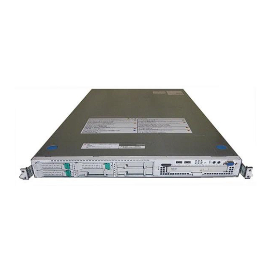
Page 35: External View
General Description 2-3 External View The following figure shows the three-hot-plug hard disk drive model. Drive cover Release buttons Logic cover... -
Page 36: Front View With Front Bezel Closed
2-4 General Description Front View with Front Bezel Closed The following figure shows the location of the front system features. Front bezel The front bezel is a cover protecting the front devices during daily operation. A security key is provided to lock the cover. Key slot Insert the security key into this slot when unlocking the front bezel. -
Page 37: Front View With Front Bezel Removed
General Description 2-5 Front View with Front Bezel Removed Hot-plug 3.5-inch hard disk drive model (SATA or SAS) See 3 - 7 on the previous page. 7-2 7-3 Hot-plug 2.5-inch hard disk drive model (SAS) See 3 - 7 on the previous page. 7-2 7-3 Handles (1 at the right and left each) Hold the handles when dismounting/mounting the server from/in the rack. -
Page 38: Rear View
2-6 General Description Rear View SATA Hot-plug 3.5-inch hard disk drive model 17-1 17-2 SAS Hot-plug 3.5-inch/2.5-inch hard disk drive model 17-1 17-2... - Page 39 General Description 2-7 Low-profile PCI board extension slot (1C) Mount PCI board of the low-profile type into this slot. Full-height PCI board extension slot (1B) Mount PCI board of the full-height type in the slot. Captive thumbscrew Secures the logic cover to the chassis. Redundant power supply slot Hot-swap SAS hard disk drive model only.
-
Page 40: Internal View
2-8 General Description Internal View The internal view for each models show below. The processor air duct factory-installed in the system is omitted for clarity. SATA Hot-swap 3.5-inch Hard Disk Drive Model Front panel board Hard disk drive bays Backplane Mother board Power supply Riser card module assembly... - Page 41 General Description 2-9 SATA 3.5-inch Hard Disk Drive Model Front panel board Hard disk drive bays Backplane Mother board Power supply Riser card module assembly Chassis intrusion switch DIMM Processor (mounted under the CPU and heat sink) Cooling fans (Each number following the bold-faced number indicates the fan number.) DVD-ROM drive...
- Page 42 2-10 General Description SAS 2.5-inch Hard Disk Drive Model Front panel board Hard disk drive bays Backplane Middle-plane Mother board Power supply Riser card module assembly Chassis intrusion switch DIMM Processor (mounted under the CPU and heat sink) Cooling fans (Each number following the bold-faced number indicates the fan number.) DVD-ROM drive...
-
Page 43: Mother Board
General Description 2-11 Mother Board 19-1 External 19-2 connector, indicators and controls FRONT REAR Power signal connector Main power connector USB file device connector USB connector Configuration jumpers Keep the settings at the factory. Connectors Not used in this system. Password clear jumper switch SATA connector 2 (SATA hard disk drive model only) Not used in this system. -
Page 44: Status Indicators
The table below explains the STATUS LED indication, the meanings, and the procedures. NOTES: If NEC ESMPRO or the offline maintenance utility is installed, you can confirm the cause of a failure by referring to the error log. If shutdown processing can be performed through the operating system when you want to restart the system after turning the power off, restart the system by performing shutdown processing. -
Page 45: General Description
General Description 2-13 STATUS LED Description Procedure indication On (green) The server is operating normally. – Flashing The server is operating with the Identify the device in degraded state • (green) memory or CPU in degraded by using the BIOS setup utility state. -
Page 46: Disk Access Led
2-14 General Description DISK ACCESS LED ( ) The DISK ACCESS LED indicates the status of the hard disk drive mounted in the 3.5-inch disk bay. The LED turns green each time access is made to the hard disk drive. When the DISK ACCESS LED turns amber, it indicates that a hard disk drive failure has occurred. -
Page 47: Hard Disk Drive Led
General Description 2-15 Hard Disk Drive LED The disk LED located on the drive carrier indicates the following depending on the status: Hard disk drive Hard disk drive Drive carrier Drive carrier Disk LED Disk LED 3.5-inch hard disk drive 2.5-inch hard disk drive Flashing (green) The LED indicates that the hard disk drive is accessed. -
Page 48: Lan Connector Leds
2-16 General Description IMPORTANT: If the server is turned off during rebuild processing, the processing is stopped. Restart the server, mount the new hard disk drive in hot swap mode, and then perform rebuild processing again. Observe the following notes on using the auto-rebuild function. Do not turn the power off. -
Page 49: Ac Power Led (Sas Hot-Swap Hard Disk Model Only)
General Description 2-17 Speed LED (for management port) This LED indicates whether each of the network ports normally equipped with the server is operated through the 100BASE-TX or 10BASE-T network interface. If the LED is lit amber, the network port is operated through 100BASE-TX. If the LED is off, the network port is operated through 10BASE-T. -
Page 50: Standard Features
Auto-rebuild feature (hot-swappable) BIOS password feature Mechanical security lock Redundant fans Management Utilities Easy and Fine Setup NEC ESMPRO NEC EXPRESSBUILDER (system setup NEC DianaScope utility) Configuration Parameter Diskette Creator Maintenance Features SETUP (BIOS configuration utility) SoftwareRAID Setup Utility (Onboard... -
Page 51: Remote Management Feature
5Vdc standby voltage, which remains active when system power is switched off, but the ac power source is still on and connected. The RMC supports the NEC DianaScope, which allows remote server management through networks. Events monitored by the manager system include over-temperature and over-voltage conditions, fan failure, or chassis intrusion. -
Page 52: Degradation Feature
Failed DIMMs and processors may be identified on the screen that the POST displays, or with the BIOS setup utility of the server, "SETUP." They may also be identified on the system that has the NEC ESMPRO installed. Memory RAS Features Your server board has the memory mirroring and online spare memory features. -
Page 53: System Security
General Description 2-21 System Security To help prevent unauthorized entry or use of the system, the system includes a full lockable front bezel and Server Management software that monitors the front bezel intrusion switch. Security with Mechanical Locks and Monitoring To unlock the bezel, insert the key in the lock and turn the lock counterclockwise until it stops (about a quarter turn). -
Page 54: Nec Expressbuilder
2-22 General Description NEC EXPRESSBUILDER The CD-ROM that comes with the server contains a setup utility called "NEC EXPRESSBUILDER." The major functions of the NEC EXPRESSBUILDER are: To install the Operating System. "Express Setup" helps you to install the Windows Operating System. (See Chapter 5) To diagnose the system. -
Page 55: Nec Esmpro
See Chapter 7 for details. NEC DianaScope The NEC DianaScope is a software for the remote management of the server. The NEC DianaScope can control the managed server even if OS is not running on the managed server. -
Page 56: Using Your Server
2-24 General Description USING YOUR SERVER This section describes basic operations of the server including how to use devices such as the DVD- ROM drive. See Appendix B for notes on using the disc and accessories including the keyboard and the mouse. - Page 57 General Description 2-25 Slide the front bezel to the left a little to remove the tab from the frame and then remove the front bezel from the server. To install the front bezel, latch the tab at the left side of the front bezel on the server frame. After the installation, lock the front bezel by using the key for security.
-
Page 58: Power Switch
2-26 General Description POWER Switch Use the POWER switch to turn on/off the server. Power On Press the POWER switch on the front of the computer chassis. The POWER LED lights in green. POWER LED POWER switch IMPORTANT: If the power cord is connected to a power control device such as a UPS (Uninterruptive Power Supply), make sure that the power control device is powered. - Page 59 ECC memory module, CPU module, keyboard, and mouse. POST also displays messages of the BIOS setup utility, such as the start-up message, while in progress. With the factory setup of the server, the NEC logo appears on the display unit while POST is in progress. (To display the POST check results, press Esc.)
-
Page 60: Post Execution Flow
2-28 General Description POST Execution Flow The following describes the progress of POST in the chronological order. IMPORTANT: Do not make key entries or perform mouse operations while POST is in progress. Some system configurations may display the message "Press Any Key"... - Page 61 General Description 2-29 If your server uses onboard RAID feature, the following message is displayed to prompt you to run RAID utility. Press <Ctrl><M> to Run LSI Logic SoftwareRAID Setup Utility Press Ctrl + M to run the utility. For detail explanation, see Chapter 4 for detail. IMPORTANT: The LSI Logic Software RAID Setup Utility is used to manage the data stored in hard disk drive, or for maintenance.
-
Page 62: Post Error Messages
2-30 General Description POST Error Messages When POST detects an error, it displays an error message on the display unit screen. See Chapter 8 for POST error codes. IMPORTANT: Take a note on the messages displayed before consulting with your service representative. Alarm messages are useful information for maintenance. -
Page 63: Identification Of Servers ~ Uid Switch
General Description 2-31 Identification of Servers ~ UID Switch ~ An "UID (Unit ID) LED" is provided on the front panel and rear panel. If more than one server is mounted in a single rack, the LED identifies the server you are going to maintain. The UID LED goes on when the UID (Unit ID) switch on the front panel is pressed. -
Page 64: Dvd-Rom Drive
2-32 General Description DVD-ROM Drive The server is provided with the DVD-ROM drive on its front to read data from a disc. CAUTION Observe the following instructions to use the server safely. Failure to follow these instructions may cause a fire, personal injury, or property damage. See pages 1-3 to 1-8 for details. - Page 65 General Description 2-33 As shown in the figure below, hold the tray with a hand and press the disc with fingers of another hand to make the hole of the disc fit to the rotor at the center of the tray. Rotor Press this part of disc.
- Page 66 2-34 General Description After taking out the disc, return the tray into the drive. When you fail to eject the tray with the Eject button and take out the disc from the server, follow the procedure below. Emergency hole Press the POWER switch to power off the server. (The POWER LED goes off.) Insert a metal pin of approximately 1.2 mm in diameter and 100 mm in length (a straightened large paper clip will make a substitute) into the emergency hole on the right front of the DVD-ROM drive and gently push it in until the tray is ejected.
- Page 67 General Description 2-35 NOTE: Use of the Disc Keep the following notes in mind to use the disc for the server: For the disk which does not conform to the CD standard, the playback of such a disk with the CD drive is not guaranteed. Do not drop the disc.
- Page 68 2-36 General Description (This page is intentionally left blank.)
-
Page 69: Chapter 3 Setting Up Your Server
Chapter 3 Setting Up Your Server This chapter describes how to set up the server appropriate for your system, on a step-by-step basis. -
Page 70: Setup Flow
Install an operating system to the server. See Chapter 5. Installing the utilities Install the utilities in the provided NEC EXPRESSBUILDER CD-ROM. See Chapter Making backup copies of system information After all the system setup procedures are completed, make backup copies of system information. -
Page 71: Selecting Server Site
Setting Up Your Server 3-3 SELECTING SERVER SITE To use the server, install it on a standard EIA 19-inch rack assembly. Refer to the documentation attached to the rack or contact your service representative for the installation of the server on the rack. WARNING Observe the following instructions to use the server safely. - Page 72 3-4 Setting Up Your Server Do not install the rack in the places listed below. Installing the rack or mounting the server on the rack in such a place may cause some malfunction to occur. Narrow space from which devices cannot be pulled out from the rack completely Place that cannot bear the total weights of the rack and devices mounted on the rack Place where stabilizers cannot be installed or where the rack can be installed only after the practice of proper earthquake-resistant construction...
-
Page 73: Installing The Server
Setting Up Your Server 3-5 INSTALLING THE SERVER With N8100-1241F/1242F/1243F/1244F/1245F/1246F/1313F/1314F/1327F/ 1328F/1329F/1330F/1331F/1332F This subsection provides the instructions for the rack-mount server unit into a standard EIA 19-inch rack cabinet. Also this subsection describes the removal procedures for the rack-mount server unit from the 19-inch rack cabinet. -
Page 74: Installation Procedure For Nec Rack/Third Vendor's Rack
3-6 Setting Up Your Server Installation Procedure for NEC Rack/Third Vendor's Rack This server can be installed in either the NEC rack or a third vendor's rack. Take the following procedure to install the server in the rack: Preparation before Installation The slide rail is fixed with the screw to prevent from falling off during transportation. - Page 75 Install three core nuts in 1U (the minimum unit of rack height). Three slots (angle holes) are opened per 1U of a rack. Install the core nuts at the three slots. (For any NEC rack, round marks are put in the unit of 1U.) For one core nut installed on the front of the rack, the lower nut is used to fix the...
- Page 76 3-8 Setting Up Your Server Hang either clip of a core nut on a square hole on the rack and insert another clip into the hole by using a tool such as a flat tip screwdriver. NOTE: Confirm that all the core nuts are installed at the level.
-
Page 77: Installing The Rail Assemblies
Setting Up Your Server 3-9 Installing the Rail Assemblies Make sure of the right side rail assembly or the left one when installing it. See the figure below. To adjust the length of the rail according to the depth of the rack, loosen screws securing the rail assembly. - Page 78 3-10 Setting Up Your Server Installing the Server CAUTION Observe the following instructions to use the server safely. Failure to follow these instructions may cause a fire, personal injury, or property damage. See pages 1-3 to 1-8 for details. Do not lift the server only by a single person. Do not pinch your finger with mechanical components.
- Page 79 Setting Up Your Server 3-11 At least two persons are required to install the server. Securely hold the server and install it in the rack. Firmly fit the inner rails on the sides of the server into the rail assemblies that are installed on the rack, and then slowly push the server into the rack.
-
Page 80: Securing The Server
3-12 Setting Up Your Server Securing the Server Push the server into the rack as far as it will go. Tighten the right and left captive thumbscrews on the front panel to secure the server to the rack. Captive thumbscrews Install the front bezel. -
Page 81: Removing The Server From The Rack Assembly
Setting Up Your Server 3-13 Removing the Server from the Rack Assembly The server should be removed from the rack by at least two persons. WARNING Observe the following instructions to use the server safely. Failure to follow these instructions may result in death or serious personal injury. See pages 1-3 to 1-8 for details. - Page 82 3-14 Setting Up Your Server Loosen the two captive thumbscrews. Captive thumbscrews Hold the handle and pull out the server from the rack slowly and carefully. The server clicks to be latched. Pull out the server from the rack with the right and left release lever pressed to release the latch.
- Page 83 Setting Up Your Server 3-15 With N8100-1301F/1302F/1304F/1305F/1306F/1308F/1309F/1310F/1312F/ 1313AF/1314AF This subsection provides the instructions for installing the server into a rack cabinet. (This subsection also describes the removal procedures.) WARNING Observe the following instructions to use the server safely. Failure to follow these instructions may result in death or serious personal injury.
- Page 84 3-16 Setting Up Your Server Installation This server can be installed in either the NEC rack or a third vendor's rack. Take the following steps to install the server in the rack. Preparation for installation The slide rail is fixed with the cable band to prevent from falling off during transportation.
- Page 85 Setting Up Your Server 3-17 While pushing the unlock button on the front of the server, hold the rails and slowly move them toward the rear of the server. Press this button to unlock the server. After a while, the rails are locked with clicking sound. Pull the release levers on the left and right sides of the server toward direction indicated by an arrow in the figure, and remove them from the server while unlocking it.
- Page 86 3-18 Setting Up Your Server While pushing the levers, move the removed rail assemblies toward the direction indicated by an arrow in the figure, to restore the original position. IMPORTANT: The removed rail assemblies are to be installed on the inner rails later.
- Page 87 Setting Up Your Server 3-19 Installing rail assemblies Insert the square projection of the rail assembly into the angle hole on the 19-inch rack until it is locked with clicking sound. The figure below shows the right side (front) of the rack. Install the rail assemblies to the right side (rear), and left side (front and rear) of the rack in the same procedure.
- Page 88 3-20 Setting Up Your Server Installing the Server CAUTION Observe the following instructions to use the server safely. Failure to follow these instructions may cause a fire, personal injury, or property damage. See pages 1-3 to 1-12 for details. Do not lift the server only by a single person. Do not pinch your finger with mechanical components.
- Page 89 Setting Up Your Server 3-21 At least two persons are required to install the server. Securely hold the server and install it in the rack. Firmly fit the inner rails on the sides of the server into the rail assemblies that are installed on the rack, and then slowly push the server into the rack.
- Page 90 3-22 Setting Up Your Server IMPORTANT: Be very careful not to get your finger caught in the levers or rails. Insert both sides of inner rails straight into the rack. Hold the thumbscrews on both sides of the server, and install the server carefully while making sure the installation position.
- Page 91 Setting Up Your Server 3-23 Installing the front bezel Install the front bezel so that the left tab on the front bezel engages with the chassis frame. Tabs...
- Page 92 3-24 Setting Up Your Server Removal Remove the server from the rack in the following procedure. CAUTION Observe the following instructions to use the server safely. Failure to follow these instructions may cause a fire, personal injury, or property damage. See pages 1-3 to 1-12 for details.
- Page 93 Setting Up Your Server 3-25 While pushing the left and the right unlock buttons on the front of the server, pull out the server from the rack slowly and carefully. The server clicks to be latched. Press this button to unlock the server.
- Page 94 3-26 Setting Up Your Server To remove the rail assembly, pull out the rail toward you while pushing the lever. Lever...
-
Page 95: Connecting Peripheral Devices
See pages 1-3 to 1-8 for details. Do not connect any interface cable with the power cord of the NEC Express Server plugged to a power source. Do not use any unauthorized interface cable. -
Page 96: Setting Up Your Server
3-28 Setting Up Your Server Device with the serial interface (Management PC only) USB device FRONT Device with the serial interface (multiport repeater) (multiport repeater) Finally connect the provided 100BASE-T/ power cord to the receptacle. 1000BASE-TX/ If connecting the server to UPS, 10BASE-T 1000BASE-TX/ see the explanation below. -
Page 97: Connecting Power Cord
Setting Up Your Server 3-29 CONNECTING POWER CORD Connect the provided power cord to the server. WARNING Observe the following instructions to use the server safely. Failure to follow these instructions may result in death or serious personal injury. See pages 1-3 to 1-8 for details. - Page 98 3-30 Setting Up Your Server To connect the power cord from the server to an uninterruptive power supply (UPS), use service outlets on the rear of the UPS. Refer to the manual that comes with the UPS. When the power cord from the server to a UPS, change the BIOS setup of the server to link with power supply from the UPS.
-
Page 99: Turning On The Server
If you have problems powering on your system, see Chapter 8. After you have successfully powered on your system, insert the NEC EXPRESSBUILDER CD- ROM into the DVD-ROM drive, reboot the system and follow the screen prompts to run NEC EXPRESSBUILDER. -
Page 100: Installing Operating System
Save the information after completing the system setup. Without the backup data, you will not be able to recover the information. You can save the information by the following process. Insert the NEC EXPRESSBUILDER CD-ROM into the DVD-ROM drive and reboot the system. Select [Tools]. -
Page 101: Chapter 4 Configuring Your Server
Chapter 4 Configuring Your Server Configuration and setup utilities are used to change your system configuration. You can configure your system, as well as option boards you may add to your system, using the BIOS SETUP Utility. Several unique system parameters are configured using the BIOS SETUP, which is stored in the system FLASH memory. -
Page 102: Starting Setup Utility
4-2 Configuring Your Server Starting SETUP Utility Powering on the server starts POST (Power On Self-Test) and displays its check results. If the NEC logo is displayed, press Esc. After a few seconds, the following message appears at bottom left on the screen. -
Page 103: Description On On-Screen Items And Key Usage
Configuring Your Server 4-3 Description on On-Screen Items and Key Usage Use the following keyboard keys to work with the SETUP utility. (Key functions are also listed at the bottom of the screen.) Indicates the current menu. Online help Indicates there window are submenus. -
Page 104: Menu And Parameter Descriptions
4-4 Configuring Your Server Menu and Parameter Descriptions The SETUP utility has the following six major menus: Main Advanced Security Server Boot Exit To set minute functions, select a submenu from the above menus. The following describes available functions and parameters, as well as the factory-set, for each menu. - Page 105 Configuring Your Server 4-5 Main Option Parameter Description Your Setting System Time HH:MM:SS Set the system time. System Date MM/DD/YYYY Set the system date. Hard Disk Pre-Delay [Disabled] Allows slower spin-up drives to come ready. 3 seconds 6 seconds 9 seconds 12 seconds 15 seconds 21 seconds...
- Page 106 4-6 Configuring Your Server Primary IDE Master/Primary IDE Slave/Secondary IDE Master/Secondary IDE Slave Correspondence between the menu items and devices: Primary IDE Master: DVD-ROM drive (standard) Primary IDE Slave: None Secondary IDE Master: None Secondary IDE Slave: None Option Parameter Description Your Setting Type...
-
Page 107: Processor Settings
Configuring Your Server 4-7 Processor Settings Option Parameter Description Your Setting Processor Retest [No] If yes, BIOS will clear historical processor status and retest the processor on the next boot. Processor Speed nnn GHz Displays clock speed for the processor. (View only) Displays CPU ID for processor, if Processor 1 CPUID Numeral... - Page 108 Displays Advanced Chipset Control submenu. Boot-time Diagnostic Enabled When disabled, the BIOS will display Screen the NEC logo during POST. Press [Disabled] Esc to switch to the POST execution screen. Reset Configuration Data [No] Select "Yes" if you want to clear the system configuration data during the next boot.
-
Page 109: Memory Configuration
Configuring Your Server 4-9 Memory Configuration Option Parameter Description Your Setting System Memory nnn KB Indicates the total capacity of the basic memory. (View only) Extended Memory nnnnnnn KB Indicates the total capacity of the extended memory. (View only) DIMM Group #1 - Normal Indicates the current memory status. -
Page 110: Pci Configuration
4-10 Configuring Your Server PCI Configuration – Onboard Video Controller submenu Option Parameter Description Your Setting VGA Controller Disabled If Disabled, the BIOS will hold the [Enabled] embedded chip in reset. Onboard VGA [Auto] Allows selecting the onboard VGA controller Option ROM Scan Force or optional PCI VGA controller as the... -
Page 111: Peripheral Configuration
Configuring Your Server 4-11 Peripheral Configuration IMPORTANT: Note that the interrupt and/or base I/O address are not overlapped with others. If the value set for the interrupt or base I/O address is used in another resource, the yellow asterisk (*) appears. Reset any item with the yellow asterisk properly. - Page 112 4-12 Configuring Your Server Advanced Chipset Control Option Parameter Description Your Setting Multimedia Timer [Disabled] Specify whether the system supports the multimedia timer feature. Enabled Intel(R) I/O AT Disabled Enables or disables the Intel(R) Acceleration technology. [Enabled] Wake On Disabled Specify whether the remote power-on LAN/PME function through embedded NIC and...
-
Page 113: Configuring Your Server
Configuring Your Server 4-13 Security The Security menu appears if you move the cursor to the position of "Security." Press Enter on "Set Supervisor Password" or "Set User Password," to display the following screen. Enter the passwords on the dialog box. Passwords may have up to eight characters including alphanumerics and symbols. - Page 114 4-14 Configuring Your Server Option Parameter Description Your Setting Set User Up to eight Supervisor password controls access Password alphanumerics to the setup utility. When Enter is pressed, the user is prompted for a password; press Esc to abort. Once set, this can be disabled by setting it to a null string, or by clearing password jumper on system board (refer to Configuring...
- Page 115 Specify whether to enable or disable the boot monitoring function on booting, or 5 Minutes select the time limit for timeout. 10 minutes To use this function, install NEC 15 minutes ESMPRO Agent. Set this item to 20 minutes "Disabled" if the system is booted from...
- Page 116 4-16 Configuring Your Server Option Parameter Description Your Setting Thermal Sensor Disabled Specify whether to enable or disable the thermal sensor monitoring function. If a [Enabled] thermal error is detected with this item being set to "Enabled", the system stops at the end of POST.
-
Page 117: System Management Submenu
Configuring Your Server 4-17 System Management Submenu Option Parameter Description Your Setting BIOS Version – Displays the current BIOS version. (View only) Board Part Number – Displays the part number of mother board. (View only) Board Serial Number – Displays the serial number of mother board. - Page 118 4-18 Configuring Your Server Console Redirection Submenu Option Parameter Description Your Setting BIOS Redirection [Disabled] Specify the address/interrupt of the serial port to which a remote console Port Serial Port A is connected. Serial Port B ACPI Redirection [Disabled] Specify the serial port to which an Port ACPI console is connected.
- Page 119 Configuring Your Server 4-19 Boot If you move the cursor to the position of "Boot," the Boot menu appears, which is used to set the boot priority. Indication Device USB CDROM USB CD-ROM drive IDE CD ATAPI CD-ROM (including DVD-ROM drive) USB FDC USB floppy disk drive USB KEY...
- Page 120 4-20 Configuring Your Server Exit The options on the menu are described below. IMPORTANT: For SATA hard disk drive model, record the current SATA controller options in the Peripheral Configuration page of the Advance menu before reloading the Setup or custom defaults. The SATA controller options affect the RAID configuration.
-
Page 121: Raid Configuration
Configuring Your Server 4-21 RAID CONFIGURATION This section describes how to configure the internal hard disk drives as the disk array drive by using the onboard RAID controller. Refer to the manual of the optional disk array controller for how to configure the hard disk drives by using the optional disk array controller. -
Page 122: Installing The Hard Disk Drives
4-22 Configuring Your Server RAID10 (spanning of RAID1) RAID10 is a RAID level combined with RAID0 and RAID1. Stores data on hard disk drives by dividing it (striping). Then, each striped data is written onto hard disk drives in mirroring mode. Owing to this feature, high disk access performance of RAID0 and, in addition, high reliability of RAID1 can be achieved. - Page 123 Configuring Your Server 4-23 SAS Hard Disk Drive Models WARNING Observe the following instructions to use the server safely. Failure to follow these instructions may result in death or serious personal injury. See pages 1-3 to 1-8 for details. Do not disassemble, repair, or alter the server. Do not remove the lithium battery.
- Page 124 4-24 Configuring Your Server RAID configuration jumper RAID RAID RAID disabl disable enable Rear Front Remove the jumper from position 1 – 1 on jumper block. Reinstall the jumper on position 2 – 3 on jumper block. Reinstall the server removed in Step 2. Plug the power cord to your server and turn on the server.
-
Page 125: Running Lsi Logic Software Raid Setup Utility
Configuring Your Server 4-25 Running LSI Logic Software RAID Setup Utility When the following screen appears after you have powered on the server, press Esc. The POST screen appears. Check the description as shown below on the POST screen, then press Ctrl + M. LSI Logic Software RAID Setup Utility starts. - Page 126 4-26 Configuring Your Server To quit the utility, press Esc in the TOP menu of LSI Logic Software RAID Setup Utility. When a confirmation message appears, select [Yes]. When the above message appears, press Ctrl + Alt + Delete. The server is rebooted.
-
Page 127: Menu Tree
Configuring Your Server 4-27 Menu Tree +: Selection/execution parameter : Setting parameter. •: Information display >: Can be set (modified) after creation of logical drive Menu Description +Configure Performs Configuration settings +Easy Configuration Set configuration (Using fixed value) +New Configuration Set new configuration +View/Add Configuration Additional setting / viewing configuration... -
Page 128: Operating Procedures For Setup Utility
4-28 Configuring Your Server Operating Procedures for Setup Utility Creating/Adding Configuration Run LSI Logic Software RAID Setup Utility Set new configuration information (pack/logical drive settings) Check the logical drive settings Initialize logical drive Perform Consistency Check Exit LSI Logic Software RAID Setup Utility Run LSI Logic Software RAID Setup Utility. - Page 129 Configuring Your Server 4-29 When a confirmation message (Proceed?) is displayed, select "Yes." The SCAN DEVICE starts (scanning information is displayed at the bottom of the screen). Upon completion of SCAN DEVICE, the "New Configuration - ARRAY SELECTION MENU" screen appears. Move the cursor onto the hard disk drive to be packed by using cursor key and then press Space to select the hard disk drive.
- Page 130 4-30 Configuring Your Server Press F10 to create logical drive. The "Logical Drives Configure" screen appears. (The figure below shows an example of RAID1 configured with two hard disk drives.) Select "RAID," "Size", "DWC", "RA", or "Span" by using cursor keys. Then press Enter to fix the selection and set each value.
- Page 131 Configuring Your Server 4-31 (5) "Span: Sets Span. Parameter Remarks SPAN=NO Does not set span. SPAN=YES Sets span. When performing SPAN, create two or more sets of the same pack at pack creation, as shown in the figure below. SPANNING of RAID1 When all settings are completed, select "Accept"...
- Page 132 4-32 Configuring Your Server Execute Check Consistency on the logical drive that has been initialized. See "Check Consistency" for details. Press Esc to return to the TOP menu and exit from LSI Logic Software RAID Setup Utility. IMPORTANT: Be sure to execute Check Consistency after creating configuration. Check Consistency has two modes: "check and recover"...
-
Page 133: Manual Rebuild
Configuring Your Server 4-33 Manual Rebuild Replace hard disk drive Run LSI Logic Software RAID Setup Utility Execute rebuilding Exit LSI Logic Software RAID Setup Utility Replace a hard disk drive and turn on the server. Run LSI Logic Software RAID Setup Utility. Select "Rebuild"... - Page 134 4-34 Configuring Your Server Setting Hot Spare Install a hard disk drive Run LSI Logic Software RAID Setup Utility Set for hot spare. Exit LSI Logic Software RAID Setup Utility Install a hard disk drive to be used as hot spare, and then turn on the server. Run LSI Logic Software RAID Setup Utility.
- Page 135 Configuring Your Server 4-35 Press Esc to return to the TOP menu and exit LSI Logic Software RAID Setup Utility. IMPORTANT: Select "Objects" → "Physical Drive" → "Port #X" → "Force Offline" to cancel the hot spare setting. When two or more hard disk drives (of the same capacity) are assigned as hot spare, rebuilding is performed in order starting from the one with the smaller CH number/ID number.
-
Page 136: Check Consistency
4-36 Configuring Your Server Check Consistency Run LSI Logic Software RAID Setup Utility Perform Check Consistency Exit LSI Logic Software RAID Setup Utility Run LSI Logic Software RAID Setup Utility. Select "Check Consistency" from the TOP menu. The "Logical Drives" screen appears. Move the cursor onto the logical drive to be checked, and press Space to select it. - Page 137 Configuring Your Server 4-37 Others Clear Configuration Clears configuration information. Select "Configure" → "Clear Configuration" from the TOP menu. Executing "Clear Configuration" clears all configuration information on the disk array controller and hard disk drives. The configuration information on all channels of the disk array controller is also cleared.
-
Page 138: Configuring Mother Board Jumpers
4-38 Configuring Your Server CONFIGURING MOTHER BOARD JUMPERS With the pre-installed SETUP utility, you can set desired passwords to protect the data stored in the server against access from unauthorized users. When you forget the passwords, however, you may want clear them. The following describes how to clear these passwords. You can also use the following procedure to clear the CMOS data in the server. - Page 139 Configuring Your Server 4-39 Pin for protecting/ Pin for protecting/ clearing the CMOS clearing the password contents Protect Protect Clear Clear Rear Front The following describe the clearing procedure. WARNING Observe the following instructions to use the server safely. Failure to follow these instructions may result in death or serious personal injury.
- Page 140 4-40 Configuring Your Server CAUTION Observe the following instructions to use the server safely. Failure to follow these instructions may result in death or serious personal injury. See pages 1-3 to 1-8 for details. Never attempt to lift the server only by yourself. Make sure to complete board installation.
-
Page 141: Chapter 5 Installing The Operating System With Express Setup
Chapter 5 Installing the Operating System with Express Setup This section describes information on using Express Setup to install and configure the following operating systems to the server. Microsoft® Windows Server® 2003 R2 Standard Edition / Microsoft® Windows Server® 2003 R2 Enterprise Edition Microsoft®... -
Page 142: About Express Setup
Storage Device" that ships with optional boards, a parameters file is mandatory. You can create a parameters file in advance using "Configuration Diskette Creator" included in NEC EXPRESSBUILDER. "Configuration Diskette Creator" has a function of "Mass installation". You can replicate configuration files and modify a replicated file by using this function, depending on individual server system (see Chapter 6). -
Page 143: Installation Notice
Confirm if the BIOS settings are correct before installing the Windows Server 2003. See Chapter 4 to confirm the settings. NEC ESMPRO Agent NEC ESMPRO Agent requires to install the necras.sys driver on your Windows system. If you install the Windows without using the Express Setup, run the "Update Express5800 system" in Master Control Menu. - Page 144 5-4 Installing the Operating System with Express Setup Supported Mass Storage Controllers The NEC EXPRESSBUILDER CD-ROM attached to your system supports the following mass storage controllers for installation. NOTE: If you want to install the other boards by using a driver floppy disk ("OEM-FD for Mass storage device"), except ones listed below,...
-
Page 145: Windows Server 2003
Installing the Operating System with Express Setup 5-5 Windows Server 2003 Express Setup can install the Windows Server 2003. Confirm below notes before installing the Windows. IMPORTANT: Complete all the process of hardware settings (BIOS and optional board settings) before starting the installation. See "Setup for Solving Problems"... -
Page 146: Creating Partition Size
5-6 Installing the Operating System with Express Setup Creating Partition Size The size for the partition that the system is to be installed can be calculated from the following formula. Size necessary to install the system + Paging File Size + Dump File Size + Application Size Size necessary to install the system = 3500MB (Windows Server 2003 R2) 3500MB... - Page 147 Installing the Operating System with Express Setup 5-7 Re-installing to the hard disk drive which has been upgraded to Dynamic Disk You cannot re-install Windows Server 2003 with the current partition of the hard disk drive upgraded to Dynamic Disk kept remained. If you want to keep the current partition remained, see Appendix E to re-install the system.
-
Page 148: Installation Flow
Create New File No Floppy Disk Confirm the specification and input the value In case [Skip] is selected Remove the Floppy Disk and Copying NEC Modules CD-ROM from the Drive ↓ Copying Selected Application Modules Insert Windows CD-ROM Agree Software License Agreement... -
Page 149: Installing The Windows Server 2003
"Reinstalling the operation system when multiple logical drives exist" (Appendix E). Insert the NEC EXPRESSBUILDER CD-ROM into the DVD-ROM drive of the server. Press Ctrl, Alt, and Delete to reboot from the NEC EXPRESSBUILDER. The system boots from the CD-ROM and NEC EXPRESSBUILDER starts. - Page 150 5-10 Installing the Operating System with Express Setup The message, "Do you want to use the parameters file in order to set up the Express server or workstation?", appears. If you want to use the parameters file, click [Yes]. If not, click [No]. "NOTE"...
- Page 151 Installing the Operating System with Express Setup 5-11 Select the installing Operating system. Select "Windows" from the menu. Next, [Basic Information] wizard appears. Confirm the parameters, modify if necessary, and then click [Next]. After that, click [Next], [Back], or [Help] on the screen to continue. Modify the parameters each time if necessary.
- Page 152 NOTE: You can use this function only when the floppy disk drive is attached to the system. Remove the NEC EXPRESSBUILDER CD-ROM from the DVD-ROM drive according to the message. If you proceed the setup by using setup parameter file, remove the floppy disk from the floppy disk drive.
- Page 153 Installing the Operating System with Express Setup 5-13 If you selected [Yes] on [Apply Service Pack] at Basic Information, follow the procedure below. 1) Follow the message to take Windows Server 2003 CD-ROM out of the DVD-ROM drive. 2) Follow the message to insert Windows Server 2003 Service Pack 1 or later into the DVD-ROM drive.
-
Page 154: Installing And Setting Device Drivers
PROSet is necessary to utilize these features. Follow the procedure below to install PROSet. Insert the NEC EXPRESSBUILDER CD-ROM into the DVD-ROM drive. The [Windows Explorer] dialog starts. * The procedure in the case of the standard start menu Click Start menu and click [Windows Explorer]. -
Page 155: Network Driver
Installing the Operating System with Express Setup 5-15 Network Driver Specify the details of network driver. One standard network driver that is mounted will be installed automatically, but the link speed and Duplex mode need to be specified manually. [When PROSet is not installed] The [Local Area Connection Properties] dialog box appears. - Page 156 5-16 Installing the Operating System with Express Setup NOTE: It is recommend to add [Network Monitor] at [AddingServices]. [Network Monitor] can monitor the frame (or the packet)that the computer installing [Network Monitor] sends or receives. This tool is valuable when analyzing network trouble. For information on how to install the tool, see the "Setting for Solving Problems"...
-
Page 157: Optional Network Board Driver
If you want to utilize optional Network Board (N8104-112/119/111/120/121/122), the network driver will be installed automatically. Therefore, the driver attached to the Network board should not be used. If you want to utilize optional Network Board (N8104-86/111), install the driver stored in NEC EXPRESSBUILDER CD-ROM. In case of utilizing (N8104-111/86) "DVD-ROM Drive Letter:\WINNT\DOTNET\NS4\PRO100\WS03XP2K"... -
Page 158: Adapter Fault Tolerance (Aft)/Adaptive Load Balancing (Alb)
5-18 Installing the Operating System with Express Setup Adapter Fault Tolerance (AFT)/Adaptive Load Balancing (ALB) Adapter Fault Tolerance (AFT) is a feature that creates a group containing more than one adapter and automatically converts the process of the working adapter to the other adapter in the group when any trouble occurred on that adapter. -
Page 159: Graphics Accelerator Driver
The graphics accelerator driver will be automatically installed by Express Setup or system update. SCSI Controller Driver (N8103-75/95/N8190-126) If you utilize SCSI controller driver (N8103-75/95/N8190-126), update your system with NEC EXPRESSBUILDER CD-ROM attached to your system. The SCSI controller driver will be installed automatically. -
Page 160: Notes On Using The N8103-75 Controller Board
Select "Don't search. I will choose the driver to install" and click [Next]. Click [Have Disk..]. Insert "Windows Server 2003 OEM-DISK for NEC EXPRESSBUILDER" into the floppy disk drive, enter "a:\" into "copy manufacturer's file from:" and click [OK]. Specify the following driver and click [Next]. -
Page 161: Available Switch Options For Windows Server 2003 Boot.ini File
Installing the Operating System with Express Setup 5-21 Available switch options for Windows Server 2003 Boot.ini file Many different switches will be available if you edit Boot.ini file. For the available switch options, refer to the following information: Microsoft Knowledge Base - Article ID: 833721 "Available switch options for the Windows XP and the Windows Server 2003 Boot.ini files"... -
Page 162: Setting For Solving Problems
5-22 Installing the Operating System with Express Setup SETTING FOR SOLVING PROBLEMS Setup the following issue in advance so that your computer can recover from any trouble precisely and as soon as possible when it should occur. Memory Dump (Debug Information) This section describes the procedures for collecting memory dump (debug information) in the server. - Page 163 Installing the Operating System with Express Setup 5-23 IMPORTANT: Windows Server 2003 x64 Editions To specify "Complete Memory Dump" to write the debug information is recommended. If the mounted memory size is larger than 2GB, "Complete Memory Dump" cannot be specified so that specify "Kernel Memory Dump"...
- Page 164 5-24 Installing the Operating System with Express Setup Specify "Complete memory dump" and modify [Dump file:] in the [Write debugging information] group box. e.g. Write the debug information in D drive write the file name "MEMORY.DMP". D:\MEMORY.DMP Click [Settings] on the [Performance] group box. The [Performance Options] window appears.
-
Page 165: Windows Dr. Watson
Installing the Operating System with Express Setup 5-25 Windows Dr. Watson Windows Dr. Watson is a debugger for application errors. If any application error is detected, Dr. Watson diagnoses the server and logs diagnostic information (log). Follow the procedure below and specify Dr. -
Page 166: Network Monitor
To start Network Monitor, point to [Program] → [Administrative Tools] and click [Network Monitor]. For information on how to operate Network Monitor, refer to Online Help. INSTALLING MAINTENANCE UTILITIES Various maintenance utilities are contained in your NEC EXPRESSBUILDER CD-ROM. See Chapter 6 for installing the utilities to your server or management workstations. -
Page 167: Updating The System - Installing Service Pack
Log on to the system with the account that has administrative authority (e.g. Supervisor) and insert the NEC EXPRESSBUILDER CD-ROM into the DVD-ROM drive of the server. [Setup] in [Master Control Menu] screen appears, so left-click the item. Click [Update the System] from the menu and the setup will start. -
Page 168: Installing With The Oem-Fd For Mass Storage Device
If you would like to install or re-install the OS when the system has new mass storage device not to be supported by NEC EXPRESSBUILDER, you have to set as follows. Read the manual supplied with the mass storage device before setting the server. - Page 169 Chapter 6 Installing and Using Utilities This section describes how to use the NEC EXPRESSBUILDER CD-ROM that comes with your server and to install the utilities stored on the NEC EXPRESSBUILDER.
- Page 170 NEC EXPRESSBUILDER has two executing modes depending on your operating environments. One is for using on Windows system, and the other is booted from NEC EXPRESSBUILDER CD. DOS-based with local console The following menu appears on the local display after booting from NEC EXPRESSBUILDER CD.
-
Page 171: Chapter 6 Installing And Using Utilities
Installing and Using Utilities 6-3 Windows-based This program is called as "Master Control Menu" that can run under the Microsoft Windows system (Windows 95 or later and Windows NT 4.0 or later). You can install the several applications and read the documentation from the menu. -
Page 172: Nec Expressbuilder
ROM drive of your server. Ensure that the floppy disk drive is empty. Press the RESET switch or press Ctrl, Alt, and Delete to reboot from the NEC EXPRESSBUILDER. (You may also turn off and then on again to reboot the server.) -
Page 173: Express Setup
If you install Windows Server 2003, after a few tasks are completed, all that remains to be done is to remove the NEC EXPRESSBUILDER CD-ROM and install the Windows CD-ROM, input a product ID number, and acknowledge the license agreement. - Page 174 NEC EXPRESSBUILDER CD-ROM contains a number of device drivers and utilities that you can put on floppy disks and load onto your system. Using this menu creates a support disk by copying from the NEC EXPRESSBUILDER CD-ROM. If your system has the Windows operating system, you may find it more convenient to use NEC EXPRESSBUILDER for Windows-based to make support disks.
- Page 175 – Create Maintenance Partition NEC EXPRESSBUILDER creates about 55MB of the maintenance partition on the system disk (or disk array system) as work area. The various utilities are installed when the maintenance partition is created successfully or when the maintenance partition is already created.
- Page 176 BIOS/FW/etc. Update This menu allows you to update the software module such as BIOS and firmware of the server by using the update disk (3.5-inch floppy disk) that is distributed from NEC customer service representative. After rebooting the system, an update program is started automatically from the floppy disk, and the various BIOS and firmware programs are updated.
-
Page 177: Nec Expressbuilder For Dos-Based With Remote Console
Installing and Using Utilities 6-9 NEC EXPRESSBUILDER for DOS-based with Remote Console This subsection describes the procedures for using NEC EXPRESSBUILDER for DOS-based with remote console. NEC EXPRESSBUILDER contains the remote console feature that allows the system administrator to set up the server from the management workstation (management PC) via the network or the server's COM B (serial) port. - Page 178 Running NEC EXPRESSBUILDER from the management PC via LAN Running NEC EXPRESSBUILDER from the management PC via direct connection (COM B) For the procedure for starting NEC EXPRESSBUILDER for DOS-based with Remote Console, see "NEC DianaScope". IMPORTANT: Do not change the boot device order in BOOT menu in BIOS SETUP.
- Page 179 Automatically sets up the server. Tools Launch the features of NEC EXPRESSBUILDER individually. Help Help message on NEC EXPRESSBUILDER. Quit Quit NEC EXPRESSBUILDER. Setup The NEC EXPRESSBUILDER checks the hardware configuration of the server. The disk array and maintenance partition are automatically configured.
- Page 180 Tools When you select the [Tools] on the Top Menu, the following screen appears. The menu items available only in remote console operation among those described in section "NEC EXPRESSBUILDER for DOS-based with Local Console" are displayed. See the previous subsection for detailed explanation of menu items.
-
Page 181: Nec Expressbuilder For Windows-Based (Master Control Menu)
Some documents are provided in the PDF format. Use the Adobe Reader to read these documents. Insert the NEC EXPRESSBUILDER CD-ROM into the DVD-ROM drive. Master Control Menu appears on the screen automatically. If the Autorun function is invalid in your system, run the \MC\1ST.EXE file in the CD-ROM directly. -
Page 182: Configuration Diskette Creator
Also, you can install the system with the same specification as before when re-installing the system. We recommend you to create [Configuration Diskette] to setup the servers from NEC EXPRESSBUILDER. IMPORTANT: You can not create [Configuration Diskette] for Microsoft Windows Server 2003 x64 Editions. - Page 183 Installing and Using Utilities 6-15 Click [Configuration Diskette Creator]. Configuration Diskette Creator window is displayed. Click [Create New Information files] from the [File] menu. The [Disk Environment] dialog box will be displayed. Specify each item and click [OK]. The dialog boxes to specify setup information will be displayed in order, such as [Basic Information] dialog box.
- Page 184 6-16 Installing and Using Utilities Follow the message to specify each item on the dialog box and click [Next]. NOTE: If you click on [Cancel], all the input value will be deleted. When completing the specification of setup information, the [Save Setup Information] dialog box will appear.
- Page 185 Installing and Using Utilities 6-17 Installing Optional Mass Storage Driver To install optional Mass Storage Driver that is supported by the Express Setup, follow the procedure below to create [Configuration Diskette]. Display Configuration Diskette Creator window. From the [File] menu, click [Create new information files]. [Disk Environment] dialog box will be displayed.
-
Page 186: Nec Esmpro
6-18 Installing and Using Utilities NEC ESMPRO The NEC ESMPRO lets a system administrator manage remote servers across a network. NEC ESMPRO monitors server hardware and software configurations, failures, and performance. With log data collected by NEC ESMPRO, a system administrator can track long-term and short-term performance, monitor server usage, create graphs to record trends, and check server failure rates. -
Page 187: Web-Based Promise Array Manager
Installing and Using Utilities 6-19 Web-based Promise Array Manager Web-based Promise Array Manager is a RAID management utility for monitoring SATA2 RAID controller. Refer to online documentation (pdf format) contained in NEC EXPRESSBUILDER CD-ROM for detailed explanation. -
Page 188: Power Console Plus
LSI Logic. Use of Power Console Plus enables operations (e.g., monitoring and maintenance) of RAID systems that are constructed on local NEC Express servers and NEC Express servers connected through networks (TCP/IP). The operations can be done online on graphical screens without the system being stopped. - Page 189 Installing and Using Utilities 6-21 MegaRAID Registration Server Enables control of the MegaRAID controller via the network. Install in one of NEC Express servers and management PCs that are connected through network. The above components must be installed correctly for establishing the environment to use Power Console Plus.
-
Page 190: Server Setup
6-22 Installing and Using Utilities Server Setup This section explains Power Console Plus setup in the NEC Express server in which the MegaRAID controller is mounted. Operating Environment This section explains the operating environment required for Power Console Plus to operate on a server. -
Page 191: Management Pc Setup
This section explains the operating environment required for Power Console Plus to operate on a management PC. Hardware – Machine: NEC Express5800 series PC/AT-compatible machine (which contains Intel Pentium or a CPU at least equivalent to it) – Memory: Size large enough for OS operation + 8MB or more –... -
Page 192: Nec Dianascope
NEC DianaScope NEC DianaScope is software for the remote management of the server. See the online documents for details on the functions and installation of NEC DianaScope. NOTE: You need the server license to activate DianaScope for this product. The server license below is attached to this product. -
Page 193: Megaraid Storage Manager Tm (Server)
MSM. Setup with Express Setup You can install MSM with Express Setup contained in NEC EXPRESSBUILDER CD-ROM. When you start the Express Setup, a dialog to specify an application appears. Select [MSM] on the dialog. - Page 194 6-26 Installing and Using Utilities (This page is intentionally left blank.)
-
Page 195: Chapter 7 Maintenance
MAKING BACKUP COPIES NEC recommends you make backup copies of your valuable data stored in hard disk drives of the server on a regular basis. For backup storage devices suitable for the server and backup tools, consult with your service representative. -
Page 196: Cleaning
7-2 Maintenance CLEANING Clean the server on a regular basis to keep the server in a good shape. WARNING Observe the following instructions to use the server safely. Failure to follow these instructions may result in death or serious personal injury. See pages 1- 3 to 1-8 for details. -
Page 197: Cleaning The Server
Maintenance 7-3 Cleaning the Server For daily cleaning, wipe the external surfaces of the server with a dry soft cloth. Follow the procedure below if stains remain on the surfaces: IMPORTANT: To avoid altering the material and color of the server, do not use volatile solvents such as thinner and benzene to clean the server. -
Page 198: Cleaning The Interior
7-4 Maintenance Cleaning the Interior One of the most important items in a good maintenance program is regular and thorough cleaning of the interior of the server, especially around the mother board. Dust buildup inside the server can lead to several problems. As dust acts as a thermal insulator, a buildup can prevent proper system cooling. -
Page 199: Cleaning The Keyboard/Mouse
Maintenance 7-5 Cleaning the Keyboard/Mouse Make sure that the server and peripheral devices are all off-powered (the POWER/SLEEP LED goes off), and then wipe the keyboard surface with a dry cloth. The mouse operation depends on the degree of smoothness of the internal ball rotation. To keep the mouse ball clean, use the mouse in a place with little dust. -
Page 200: Cleaning Disc
7-6 Maintenance Cleaning Disc A dusty disc or dust-accumulated tray causes the device to fail to read data correctly. Follow the procedure below to clean the tray and disc regularly: Make sure that the server is powered (the POWER/SLEEP LED is lit). Press the CD tray Open/Close button on the front of the DVD-ROM drive. -
Page 201: System Diagnostics
Maintenance 7-7 SYSTEM DIAGNOSTICS The System Diagnostics runs several tests on the server. Select [Tools] - [System Diagnostics] in the NEC EXPRESSBUILDER to diagnose the system. Test Items The following items are tested in system diagnostics. Memory CPU cache memory... -
Page 202: Startup And Exit Of System Diagnostics
The step which the step which local console of the server is used for, and remote console are used for is different. Refer to "NEC EXPRESSBUILDER" of Chapter 6 "Installing and Using Utilities", to start the system properly. The following menu is displayed on the screen, when starting the system from the NEC EXPRESSBUILDER. - Page 203 Maintenance 7-9 Select [System Diagnostics]. The system diagnostics starts and will be completed in approximately three minutes. When the diagnostics is completed, the screen of the display changes as shown below: Diagnostics tool title Test window title TeDoLi (TEst & Diagnosis On Linux) Ver001.00 (Build020901.1.1m) Test End Start 10:06:58 End 10:09:58 Pass 000:03:00 TestTime 000:03:00 Test result...
- Page 204 <Reboot> Reboots the system. Select <Reboot> in the [Enduser Menu] above. The server restarts and the system is started from the NEC EXPRESSBUILDER. Exit the NEC EXPRESSBUILDER, and remove the CD-ROM from the DVD-ROM drive. Power off the server and unplug the power cord from the receptacle.
-
Page 205: Relocating/Storing The Server
Maintenance 7-11 RELOCATING/STORING THE SERVER Follow the procedure below to relocate or store the server: CAUTION Observe the following instructions to use the server safely. Failure to follow these instructions may cause a fire, personal injury, or property damage. See pages 1-3 to 1-8 for details. - Page 206 7-12 Maintenance (This page is intentionally left blank.)
-
Page 207: Chapter 8 Troubleshooting
Chapter 8 Troubleshooting If your server does not operate as expected, read this chapter before assuming a failure. NOTE: For provision against an unexpected failure, it is recommended to install the maintenance utility, NEC ESMPRO, to the server and client computers. -
Page 208: System Viewers
Monitor the occurrence of fault by NEC ESMPRO during the system operation. Especially take note on whether any alert is reported to NEC ESMPRO Manager on the management PC. Check whether any alert is reported on the Operation Window, Data Viewer, or Alert Viewer of NEC ESMPRO Manager. -
Page 209: Leds
Troubleshooting 8-3 LEDS The server includes LEDs to indicate the server states by a variety of colors and display patterns on the front panel, hard disk drive, and power supply. Chapter 2 "Status Indicators" lists the LED displays and their meanings and the actions taken at occurrences of failures. -
Page 210: Error Messages
8-4 Troubleshooting ERROR MESSAGES If an error occurs in the server, an error message appears on the display unit connected to the server. Error Messages after Power-on Powering on the server automatically starts the self-diagnostic program, POST (Power On Self- Test). -
Page 211: Post Error Messages
Troubleshooting 8-5 POST Error Messages When POST detects an error, it displays an error message on the display unit screen. The following table lists error messages and actions to take. IMPORTANT: Take a note on the messages displayed before consulting with your service representative. Alarm messages are useful information for maintenance. -
Page 212: Troubleshooting
8-6 Troubleshooting Error Error message Recommended Action code 02D1 System Memory exceeds the CPU's caching Contact your service representative. limit. 02F4 EISA CMOS not write able. 02F5 DMA Test Failed. 02F6 Software NMI Failed. 02F7 Fail-safe Timer NMI Failed. 0B22 Processors are installed out of order. - Page 213 Troubleshooting 8-7 Error Error message Recommended Action code 8100 Memory Error detected in DIMM group #1. Contact your service representative to replace the DIMM in the relevant group. 8101 Memory Error detected in DIMM group #2. 8102 Memory Error detected in DIMM group #3. 8103 Memory Error detected in DIMM group #4.
- Page 214 Storage Controller in slot n (n: slot number) expansion ROM by using the BIOS SETUP utility (see Chapter 4). H/W Configuration of BMC is corrupted. Use the NEC EXPRESSBUILDER to configure the remote management card !! Update BMC F/W Configuration by (see Chapter 6).
-
Page 215: Beep Codes
Troubleshooting 8-9 Beep Codes If an error occurs during the POST, the server beeps, indicating the type of error. Each number indicates the number of short beeps, and a hyphen indicates a pause. For example, the beep interval 1-5-2-2 indicates 1 beep, pause, 2 beeps, pause, 2 beeps, pause, and 3 beeps notifying that no processor is detected on the mother board. -
Page 216: Error Messages On Virtual Lcd
8-10 Troubleshooting Error Messages on Virtual LCD NEC EXPRESSSCOPE Engine (Remote Management Controller) on your server board allows you to monitor the server status on the WEB browser-based screen of the client PC via network. The virtual LCD (16 digits x 2 lines) in the "Host Information" area displays the POST codes and status message. - Page 217 Troubleshooting 8-11 On-screen message Description Action Memory C-Err XX A correctable error frequently occurs Contact your service in DIMM #XX. representative. Memory U-Err XX An uncorrectable error has occurred in DIMM #XX. PCI Bus PERR XX A PERR has occurred in the PCI bus PCI Bus SERR XX A SERR has occurred in the PCI bus Prepare To Boot...
- Page 218 8-12 Troubleshooting On-screen message Description Processor 2 IERR SMI timeout SMI timeout occurred. Sys Fan 1 Alarm FAN#1 alarm occurred. Sys Fan 2 Alarm FAN#2 alarm occurred. Sys Fan 3 Alarm FAN#3 alarm occurred. Sys Fan 4 Alarm FAN#4 alarm occurred. Sys Fan 5 Alarm FAN#5 alarm occurred.
-
Page 219: Solving Problems
Troubleshooting 8-13 SOLVING PROBLEMS When the server fails to operate as expected, see the following to find out your problem and follow the instruction given before asking for repair. If the server still fails to operate successfully after solving your problem, take a note on the on- screen message and contact your service representative. - Page 220 8-14 Troubleshooting No screen display appears with beep: → Check whether DIMMs are connected to the mating connectors firmly. → Check whether DIMMs of different specifications are installed in the specific bank. See Chapter 9 for the specifications of DIMMs. →...
- Page 221 Troubleshooting 8-15 Fail to access to internal or external devices (or such devices fail to operate): Are cables properly connected? → Make sure that the interface cables and power cord are properly connected. Also make sure that the cables are connected in the correct order. Is the power-on order correct? →...
- Page 222 8-16 Troubleshooting The keyboard or mouse fails to operate: Is the cable properly connected? → You must use the provided keyboard/mouse branch cable (Y cable) for this server. Make sure that the provided cable is connected to the correct connector on the rear of the server.
- Page 223 Fail to access the (internal or external) SCSI devices: Is the SCSI device applicable to the server? → Operation of any SCSI device that is not authorized by NEC is not guaranteed. Are SCSI devices properly configured? → When the server has external SCSI devices connected, hard disk drive settings, including SCSI ID and terminator, are required.
- Page 224 8-18 Troubleshooting The server is not found on the network: Is the LAN cable connected? → Make sure to connect the LAN cable to the network port on the rear of the server. Also make sure that the LAN cable to use conforms with the network interface standard.
-
Page 225: Problems With Disk Array Configuration
Troubleshooting 8-19 Problems with Disk Array Configuration Check the following if the server configuring a disk array does not operate properly or a utility does not operate correctly. If a relevant item is found, follow the processing method. Fail to display the BIOS banner to run the utility: Is the mother board configured? →... -
Page 226: Problems With Windows Server 2003 X64 Editions
8-20 Troubleshooting Auto rebuild fails: Was a sufficient time taken for hot swap of hard disk drives? → To allow the auto rebuild to operate correctly, it should take 90 seconds or longer for the interval between the removal of the failed hard disk drive and the installation of a new hard disk drive. -
Page 227: Problems With Windows Server 2003 R2
→ If you use "Hardware Management" which is provided by Windows Server 2003 R2, above-shown event log will be registered. For more details, refer to "Enabling Microsoft Windows Server 2003 R2 Hardware Management" on the following site. [NEC Express5800 Web Site] http://www.nec.co.jp/express/download/W2K3_R2... -
Page 228: Problems With Windows Server 2003
→ Take out the floppy disk and restart the server. Is the NEC EXPRESSBUILDER CD-ROM in the DVD-ROM drive? → Take out the NEC EXPRESSBUILDER CD-ROM and restart the server. Is the OS broken? → Use recovery process to recover the system. - Page 229 Troubleshooting 8-23 The system does not restart automatically when a stop error occurs, though the system is adjusted to automatically restarting: → When the system does not restart automatically, restart it manually. The system restarts automatically when a stop error occurs, though the system is NOT adjusted to automatically restarting: →...
- Page 230 8-24 Troubleshooting The Telnet Service is not installed. → Adjust the computer name to 14 characters or less, and then install the Telnet Service according to <How to install the Telnet Service>. <How to install the Telnet Service> Click [Run] on Start menu. Type "tlntsvr /service"...
-
Page 231: Problems With Nec Expressbuilder
Troubleshooting 8-25 Problems with NEC EXPRESSBUILDER When the server is not booted from the NEC EXPRESSBUILDER CD-ROM, check the following: Did you set the NEC EXPRESSBUILDER during POST and restart the server? → If you do not set the NEC EXPRESSBUILDER during POST and restart the server, an error message will appear or the OS will boot. -
Page 232: Problems With Express Setup
Protocol : TCP/IP[DHCP Specified] Service : Select sharing Microsoft network files and printer. Client : Microsoft network client. Component : SNMP Application : NEC ESMPRO Agent MegaRAID Storage Manager (When disk array system) Power Console Plus (When disk array system) - Page 233 Troubleshooting 8-27 [OK] does not appear on [Role of Computer] screen. → The [OK] does not appear if the Setup File that has already been created is loaded. → [OK] appears only when you first entered the [Role of Computer] screen. Once you go to the next screen from [Role of Computer], the [OK] will not appear even if you click [Back] to go back to the [Role of Computer] screen.
-
Page 234: Problems With Master Control Menu
8-28 Troubleshooting When more than two Network adapter are specified, the detailed specification of TCP/IP protocol are all set to use DHCP. → When more than two Network adapter are specified, the detailed specification of the protocol may all be set by default value. Re-specify the details from Control Panel. Not more than two Network adapter is connected, but the detailed specification of the protocol are all set by default.(e.g. -
Page 235: Problems With Configuration Diskette Creator
Troubleshooting 8-29 Problems with Configuration Diskette Creator The bit map of the Configuration Diskette Creator window is not displayed correctly during setting of setup information. (When the Trekking command is used) → If the specified number of colors is fewer than 256 in the display setting, the bit map is not displayed correctly, but the setup information can be displayed correctly. -
Page 236: Collecting Dr. Watson Diagnostic Information
8-30 Troubleshooting COLLECTING DR. WATSON DIAGNOSTIC INFORMATION Dr. Watson collects diagnostic information related to application errors. The location to save the information can be specified as you like. For more information, refer to Chapter 5. MEMORY DUMP If an error occurs, the dump file should be saved to acquire necessary information. If you saved the dump to DAT, write down that it is saved as "NTBackup"... -
Page 237: Saving The Dump File
Troubleshooting 8-31 Saving the Dump File Press the DUMP switch to save the dump file when an error occurs. Insert a metal pin (a straightened large paper clip will make a substitute) into the switch hole to press the DUMP switch. DUMP switch Pressing the DUMP switch saves the dump file in the specified directory. -
Page 238: Off-Line Maintenance Utility
8-32 Troubleshooting OFF-LINE MAINTENANCE UTILITY The Off-line Maintenance Utility is an OS-independent maintenance program. When you are unable to start the OS-dependent NEC ESMPRO to troubleshoot a problem, the Off-line Maintenance Utility can be used. IMPORTANT: The Off-line Maintenance Utility is intended for use of your service representative. -
Page 239: Features Of Off-Line Maintenance Utility
Without the backup data, the system-specific information and/or configuration may not be restored. Only the authorized personnel is allowed to restore the backup data. Start of Utilities With the NEC EXPRESSBUILDER, you can start the following utilities installed in the maintenance partition. – System Management –... -
Page 240: Resetting The Server
8-34 Troubleshooting RESETTING THE SERVER If the server halts before starting the OS, press and hold Ctrl and Alt and press Delete. This restarts the server. IMPORTANT: Resetting the server clears the DIMM memory and the data in process. To reset the server when it is not frozen, make sure that no processing is in progress. -
Page 241: Chapter 9 Upgrading Your Server
IMPORTANT: Optional devices described in this chapter may be installed or removed by any user. However, NEC does not assume any liability for damage to optional devices or the server or malfunctions of the server resulted from installation by the user. NEC recommends you ask your service representative for install or removing any optional devices. -
Page 242: Safety Notes
9-2 Upgrading Your Server SAFETY NOTES Observe the following notes to install or remove optional devices safely and properly. WARNING Observe the following instructions to use the server safely. Failure to follow these instructions may result in death or serious personal injury. See pages 1-3 to 1-8 for details. -
Page 243: Anti-Static Measures
Upgrading Your Server 9-3 ANTI-STATIC MEASURES The server contains electronic components sensitive to static electricity. Avoid failures caused by static electricity when installing or removing any optional devices. Wear a wrist strap (an arm belt or anti-static glove). Wear a wrist strap on your wrist. If no wrist strap is available, touch an unpainted metal part of the cabinet before touching a component to discharge static electricity from your body. -
Page 244: Preparing For Installation And Removal
9-4 Upgrading Your Server PREPARING FOR INSTALLATION AND REMOVAL Follow the procedure below to prepare for installing or removing components. Shutdown the OS. Shutdown process is not required if the hard disk drives and the additional power supply units are hot-swappable. Unlock the front bezel with the security key. - Page 245 Upgrading Your Server 9-5 With N8100-1241F/1242F/1243F/1244F/1245F/1246F/1313F/1314F/1327F/ 1328F/1329F/1330F/1331F/1332F See the section "Preparing for Installation and Removal" described earlier to prepare. NOTE: To confirm the device you are going to maintain, use the UID switch and the UID LED that goes on when the switch is pressed. Loosen the unlock buttons at the right and left sides of the front panel, and slowly pull out the server from the rack.
- Page 246 9-6 Upgrading Your Server With N8100-1301F/1302F/1304F/1305F/1306F/1308F/1309F/1310F/1312F/ 1313AF/1314AF See the section "Preparing for Installation and Removal" described earlier to prepare. NOTE: To confirm the device you are going to maintain, use the UID switch and the UID LED that goes on when the switch is pressed. Loosen the unlock buttons at the right and left sides of the front panel, and slowly pull out the server from the rack.
-
Page 247: Hard Disk Drive
Channel 1 Channel 3 IMPORTANT: Use the hard disk drives authorized by NEC. Installing a third-party hard disk drive may cause a failure of the server as well as the hard disk drive. Purchase hard disk drives of the following models: –... - Page 248 Notes on Installing N8150-207A/208A/209A Additional Hard Disk Drive (SATA2) If N8150-207A/208A/209A additional hard disk drive (SATA2) is installed in N8100- 1241F/1242F NEC Express5800/120Rg-1 (SATA model), the slot number indicated in Chassis ID is not identical to that indicated in [Disk Management] of Windows 2003.
- Page 249 Port 1 Port 2 IMPORTANT: Use the hard disk drives authorized by NEC. Installing a third-party hard disk drive may cause a failure of the server as well as the hard disk drive. Purchase hard disk drives of the following models: –...
-
Page 250: Installation
9-10 Upgrading Your Server Installation Take the following steps to install a hard disk drive. This procedure applies to all the hard disk drive bays. See the next section for the procedure installing a hard disk drive in the flex bay. NOTE: Any hard disk drive can be installed or removed in or from the server only by removing the front bezel. - Page 251 Upgrading Your Server 9-11 With the handle in the fully open position, firmly hold the drive carrier and handle, and insert it into the chassis. IMPORTANT: Do not push on the handle until the handle begins to close by itself. Carefully hold the hard disk drive with both hands.
- Page 252 9-12 Upgrading Your Server 2.5-inch SAS Hard Disk Drive See the section "Preparing for Installation and Removal" described earlier to prepare. Unlock the front bezel with the security key and remove the front bezel. Locate the slot in which you are going to install a hard disk drive. The server has six slots.
-
Page 253: Upgrading Your Server
Upgrading Your Server 9-13 IMPORTANT: Do not push on the handle until the handle begins to close by itself. Carefully hold the hard disk drive with both hands. Do not press the POWER switch during the installation or removal of the hard disk drive if your server is running. NOTE: Confirm that the handle is hooked to the frame when having inserted the hard disk drive. -
Page 254: Removal
9-14 Upgrading Your Server Removal Take the following steps to remove a hard disk drive: NOTE: If removing a failing hard disk drive, confirm the slot in which the DISK LED of the hard disk drive is amber before starting the removal. - Page 255 Upgrading Your Server 9-15 Firmly hold the handle and hard disk drive, and pull out the hard disk drive. If using the server with the hard disk drive removed, install the dummy block in the vacant slot to ensure the cooling efficiency. Install the front bezel you removed in step 2.
- Page 256 9-16 Upgrading Your Server 2.5-inch SAS Hard Disk Drive See the section "Preparing for Installation and Removal" described earlier to prepare. Unlock the front bezel with the security key, and remove the front bezel. Push the lever to unlock, and open the handle. IMPORTANT: Do not press the POWER switch during the installation or removal of the hard disk drive if your server is running.
- Page 257 Upgrading Your Server 9-17 Notes on Replacing Hard Disk Drives in the RAID Configuration When the hard disk drives are in the disk array configuration, you can restore the state before an error using the auto-rebuild feature that stores the data in the old hard disk drive into a new one. The auto-rebuild feature is available for the RAID1, RAID5, or RAID10 disk array configuration.
-
Page 258: Power Supply Unit (Sas Hot-Plug Hdd Model)
9-18 Upgrading Your Server POWER SUPPLY UNIT (SAS HOT-PLUG HDD MODEL) Your server contains one or two power supplies. The second power supply is optional and provides a redundant configuration that ensures continued operation of the system in the unlikely event one of the power supplies fails. Power supply Power supply slot (option) - Page 259 Upgrading Your Server 9-19 Insert the power supply unit. IMPORTANT: Do not touch the terminals of the power supply unit. Contact terminals Grasp the handle and firmly push the power supply. The power supply unit is locked when a distinct "click" is heard.
- Page 260 9-20 Upgrading Your Server Connect two power cords. Use the power cord provided with the standard power supply unit and the one provided with the system. The AC POWER LEDs flash when the power cords are connected. Power supply unit 2 (Standard) Power supply unit 1 (Option)
-
Page 261: Replacing A Failing Power Supply Unit
Upgrading Your Server 9-21 Replacing a Failing Power Supply Unit Replace only a failing power supply unit. IMPORTANT: Do not remove a power supply unit operating normally. NOTE: If one power supply unit fails while the server contains two power supply units in a redundant configuration, the failing power supply unit can be replaced with the system operating (power-on state). -
Page 262: Drive Cover
9-22 Upgrading Your Server DRIVE COVER Open the drive cover when installing/removing a fan assembly, processor, and backup file device or reconnecting an internal cable. Removal See the section "Preparing for Installation and Removal" described earlier to prepare. Pull out the server from the rack. Slide the drive cover toward the rear of the server while pressing the lock button on the cover. -
Page 263: Logic Cover
Upgrading Your Server 9-23 LOGIC COVER Open the logic cover when installing/removing a DIMM, processor, and PCI add-in card or reconnecting an internal cable. Removal See the section "Preparing for Installation and Removal" described earlier to prepare. Pull out the server from the rack. Loosen a captive thumbscrew at the rear of the server. -
Page 264: Installation
9-24 Upgrading Your Server Installation When installing the logic cover, confirm that the tab of the cover is securely inserted into the slot in the server frame. Slide the logic cover toward the rear of the server and secure the cover with captive thumbscrew. NOTE: If the logic cover cannot be closed firmly, remove the drive cover before installing the logic cover. -
Page 265: Dimm
DIMM directly on the desk. For static notes, see the section "Anti- static Measures" described earlier. Make sure to use the DIMM authorized by NEC. Installing a third- party DIMM may cause a failure of the DIMM as well as the server. -
Page 266: Installation Order
9-26 Upgrading Your Server Installation Order DIMMs must be populated in pairs and in the following order: Group #1, #2, #3, #4, #5, then #6. DIMM #41 DIMM #42 DIMM #43 DIMM #11 DIMM #12 DIMM #13 DIMM #21 DIMM #22 DIMM #23 DIMM #31 DIMM #32... -
Page 267: Installation
Upgrading Your Server 9-27 Installation Install a DIMM in the following procedure. IMPORTANT: The server supports DIMMs of only the low-profile type (30 mm (1.2 inches) in height). It does not support DIMMs exceeding the specified height. See the section "Preparing for Installation and Removal" described earlier to prepare. Pull out the server from the rack. - Page 268 9-28 Upgrading Your Server Install the components you removed in steps 1 to 3. Power on the server and verify that POST displays no error messages. If POST displays an error message, take a note on the message and see the POST error messages listed in Chapter 8.
-
Page 269: Removal
NOTES: To remove the failed DIMM, check the error message appearing in POST or NEC ESMPRO to identify the DIMM socket (group) in which the failed DIMM is installed. The server operates only when at least two DIMMs are installed. -
Page 270: Using The Memory Ras Features
9-30 Upgrading Your Server Using the Memory RAS Features The server has the memory mirroring and online spare memory features as well as the chipkill ECC memory feature, which can automatically correct a memory error (multi-bit error) causing system shutdown. IMPORTANT: The memory mirroring and online spare memory features are not available in the normal memory configuration. -
Page 271: Memory Mirroring
Upgrading Your Server 9-31 Memory Mirroring The memory mirroring feature writes the same data into two groups of DIMMs corresponding with each other between memory branches (mirror set) to provide data redundancy. Mother board Memory controller Branch #0 Branch #1 Group #1 Group #2 Data1... - Page 272 9-32 Upgrading Your Server Notes on Configuring Memory Mirroring In memory mirroring configuration, the menus related to memory mirroring in BIOS SETUP are grayed out and unselectable in the following cases: When you additionally install DIMMs that unable to configure memory mirroring When you remove DIMMs that takes down the memory mirroring In this case, execute [Load Setup Defaults] to cancel the memory mirroring configuration.
-
Page 273: Online Spare Memory
Upgrading Your Server 9-33 Online Spare Memory The online memory spare feature puts a group of memory devices within a memory branch into standby status as spare devices. If an unrecoverable error occurs in a DIMM of the running group, the feature automatically changes the running DIMM from the failed one to a DIMM in the standby group to continue the processing. - Page 274 9-34 Upgrading Your Server The online spare memory feature can be used under the following conditions: Install memory devices to more than one group in each memory branch. The server can operate if the memory branches may be different in the number of DIMMs. For example, no error occurs if memory branches 0 and 1 include four DIMMs (or two groups) and six DIMMs (or three groups), respectively.
- Page 275 Upgrading Your Server 9-35 Depending on specification of memory controller, the spare memory is set in unit of rank memory. The logical memory capacity of single rank memory differs from that of dual rank memory when online spare memory is specified. Single rank memory configuration Logical memory capacity = (Physical memory capacity * Number of DIMMs) –...
-
Page 276: Processor (Cpu)
Do not operate the system until confirming that the additionally installed CPU is in normal state. Make sure to use the CPU authorized by NEC. Installing a third- party CPU may cause a failure of the CPU as well as the server. -
Page 277: Installation
Upgrading Your Server 9-37 Installation Take the following steps to install the CPU. See the section "Preparing for Installation and Removal" described earlier to prepare. Pull out the server from the rack. Remove the logic cover and drive cover. Remove the processor duct from the chassis. IMPORTANT: Make sure not to damage the internal cables. - Page 278 9-38 Upgrading Your Server Open the socket lever by pushing the lever down and away from the socket. Lift the load plate. IMPORTANT: Do not touch the socket contacts. Remove the processor from the protective cover. IMPORTANT: Hold the processor only at the edges, being careful not to touch the bottom of the processor.
- Page 279 Upgrading Your Server 9-39 Hold the processor with your thumb and index fingers oriented as shown in the figure below. IMPORTANT: Make sure fingers align to the socket cutouts. Notch Pin Marker Notches Pin Marker Align notches with the socket. Lower the processor straight down without tilting or sliding it in the socket.
- Page 280 9-40 Upgrading Your Server Put the heat sink on CPU and fix the heat sink with four screws. NOTE: Be aware of direction of heat sink (see figure below). Processor 1 Processor 2 Make sure that the heat sink is level. NOTES: If the heat sink is not level, remove it, and then install it again.
- Page 281 Upgrading Your Server 9-41 Lay the USB cables as shown in the figure below. Processor duct Heat sink USB cables Reinstall the processor duct.
- Page 282 9-42 Upgrading Your Server NOTES: Place the internal USB cables inside the processor duct (see figure above). Check to see that the processor duct is firmly installed with no clearance between the duct and chassis. Put the hard disk drive signal cable under the sub-board as figure below.
-
Page 283: Removal
Upgrading Your Server 9-43 Removal To remove the CPU, prepare the removal referring to steps 1 and 4 in the installation procedure and do the reverse procedure of steps 14 to 6. IMPORTANT: Do not remove any CPU unless it is failed. After the operation, heat may make the cool seat at the bottom of the heat sink adhere to the CPU. -
Page 284: Pci Board
9-44 Upgrading Your Server PCI BOARD The server has a riser card assembly on the mother board that enable installation of PCI boards. The riser card assembly can hole up to two PCI boards. Insert PCI boards for network extension and file device function extension into PCI board slots in each riser card. -
Page 285: Notes
Upgrading Your Server 9-45 Notes Observe the following notes on installing/removing a PCI board: Do not touch the terminals of the riser cards and the leads of electronic components with your bare hand. Fingerprints and dust left on them cause the server to malfunction due to a connection failure or damage to the leads. -
Page 286: Installation
9-46 Upgrading Your Server Installation Take the following steps to install a PCI board on the riser card: IMPORTANT: The full-height riser card is equipped with an "insulator (black)" to protect PCI boards. Do not remove the insulator, and handle it carefully. The insulator is not shown in the figures in this manual for simplifying the illustrations. - Page 287 Upgrading Your Server 9-47 Remove the screw from the riser card, and remove the extension slot cover. NOTE: Keep the removed extension slot cover for future use. Low-Profile side Full-height side Install the PCI board on the riser card. Align the PCI board terminal section with the riser card slot, and firmly push the PCI board until it is fully seated.
- Page 288 9-48 Upgrading Your Server Secure the PCI board with the screw you removed in step 5. IMPORTANT: This step is to protect the terminals of the riser card from dust or fingerprints. Dust and fingerprints left on them cause the server to malfunction.
-
Page 289: Removal
Upgrading Your Server 9-49 Install the components you removed previously. Verify that POST displays no error messages. If POST displays an error message, take a note on the message and see the POST error messages listed in Chapter 8. Run the BIOS SETUP utility and select "Yes" for [Advanced] → [Reset Configuration Data]. -
Page 290: Raid Controller Board
9-50 Upgrading Your Server RAID CONTROLLER BOARD Using the RAID controller allows you to use hard disk drives in the device bays of the server and those in the optional expansion disk cabinet in the disk array configuration. IMPORTANT: The disk array controller board is extremely sensitive to static electricity. -
Page 291: Removal
Upgrading Your Server 9-51 Removal Remove a disk array controller board in reverse order of the installation steps. Use of internal hard disk drives in a disk array configuration Onboard RAID Controller (RoMB) RAID controller is factory embedded in your mother board. For enabling the onboard RAID controller, refer to Chapter 4 for detail. - Page 292 9-52 Upgrading Your Server Change the cable connection as the following procedures. Remove the end of the interface cable that is plugged into the SAS (or SATA) connectors on the mother board. Reinstall the end of the interface cable just removed into the connector on the RAID controller.
- Page 293 Upgrading Your Server 9-53 Example of cabling diagram for SAS hard disk drive model Interface cable (To the backplane ) Optional RAID FRONT REAR controller Mother board IMPORTANT: Notes on Using the N8103-91 disk array controller (internal SAS HDD) Pay attention to connect the interface cable to proper cable connectors P2 and P3.
- Page 294 You can start the utility during execution of POST that automatically starts immediately after you turn on the server power switch. For details, see the online document in the NEC EXPRESSBUILDER CD-ROM provided with the server. (The utility varies depending on the disk array controller board.) For details on the data transfer rate, RAID, and array configuration, see the...
-
Page 295: Disk Expansion Unit
(RAID0, RAID1, or RAID5). (The utility varies depending on the board.) For details on settings and the setting methods, see the online document in the NEC EXPRESSBUILDER CD-ROM provided with the server or the manual provided with the board. - Page 296 9-56 Upgrading Your Server (This page is intentionally left blank.)
-
Page 297: Appendix A Specifications
100 to 120 VAC ±10%, 200 to 240 VAC ±10%, 50/60 Hz ±1 Hz Environmental Temperature 10 to 35°C (operating), -10 to 55°C (non-operating, storage) requirements Humidity 20 to 80% RH (no condensation) Others NEC EXPRESSBUILDER supported, NEC ESMPRO provided in the standard configuration * Excluding the front bezel. - Page 298 100 to 120 VAC ±10%, 200 to 240 VAC ±10%, 50/60 Hz ±1 Hz Environment-al Temperature 10 to 35°C (operating), -10 to 55°C (non-operating, storage) requirements Humidity 20 to 80% RH (no condensation) Others NEC EXPRESSBUILDER supported, NEC ESMPRO provided in the standard configuration * Excluding the front bezel.
- Page 299 100 to 120 VAC ±10%, 200 to 240 VAC ±10%, 50/60 Hz ±1 Hz Environment-al Temperature 10 to 35°C (operating), -10 to 55°C (non-operating, storage) requirements Humidity 20 to 80% RH (no condensation) Others NEC EXPRESSBUILDER supported, NEC ESMPRO provided in the standard configuration * Excluding the front bezel.
- Page 300 100 to 120 VAC ±10%, 200 to 240 VAC ±10%, 50/60 Hz ±1 Hz Environment-al Temperature 10 to 35°C (operating), -10 to 55°C (non-operating, storage) requirements Humidity 20 to 80% RH (no condensation) Others NEC EXPRESSBUILDER supported, NEC ESMPRO provided in the standard configuration * Excluding the front bezel.
-
Page 301: Appendix B Other Precautions
Server Management Software The NEC EXPRESSBUILDER CD-ROM that comes with the server contains the NEC ESMPRO utility. NEC recommends that you should install the NEC ESMPRO for effective use of the reliability enhancement features of the server. Floppy Disk The following describes use of the floppy disk. - Page 302 B-2 Other Precautions Notes on use The floppy disk is an important data storage media with delicate structure and requires care. Keep the following notes in mind to use it: Insert the floppy disk into the floppy disk drive gently as far as it goes. Attach the label to the correct position.
- Page 303 The floppy disk is a very delicate storage media. Dust or thermal changes, as well as operator's misconduct or server failures, may cause loss of data. To avoid loss of data, NEC recommends that you should make a back-up copy of your valuable data on a regular basis.
-
Page 304: Cd/Dvd Discs
Three-generation data management NEC recommends that you should employ three-generation data management for data storage. Three-generation data management uses three cartridge tapes: A, B, and C. You save data to tape A on the first day, tape B on the second day, tape C on the third day, tape A on the forth day, and so on. -
Page 305: Keyboard
Other Precautions B-5 This enables you, for example, to use tape B to restore the data when tape C makes a read error. Also when both tapes B and C make a read error, you can restore your valuable data by using the data stored in tape A. -
Page 306: Mouse
B-6 Other Precautions Mouse Like the keyboard, the mouse is a device to instruct your computer. Many OS's and application software require the mouse for operation. NOTE: Functions assigned to the mouse buttons vary depending on the software. For details, refer to the manual provided with the software. -
Page 307: Appendix C Irq
Appendix C The factory-set interrupt requests is listed below. Find an appropriate one to install an optional device. Peripheral Device (Controller) Peripheral Device (Controller) System timer Mouse Keyboard Numeric processor – Primary IDE COM2 serial port Secondary IDE COM1 serial port –... - Page 308 C-2 IRQ (This page is intentionally left blank.)
-
Page 309: Appendix D Installing Windows Server 2003 X64 Editions
NOTICE Read the following notes or information before installing the Windows Server 2003 x64 Editions. Optional Board Supported by NEC EXPRESSBUILDER The NEC EXPRESSBUILDER CD-ROM attached to your server supports the following optional boards; NOTE: If you want to install the other boards by using a driver floppy disk ("OEM-FD for Mass storage device"), except ones listed below,... - Page 310 D-2 Installing Windows Server 2003 x64 Editions <SATA Hard Disk Model> Controllers supporting installation of OS with Express Setup – N8103-101 Disk Array Controller (SATA2)* – LSI Logic Embedded MegaRAID (embedded on the mother board) Other controllers – N8103-80F Disk Array Controller (SCSI 1ch)* –...
-
Page 311: Installing Service Pack
Installing Windows Server 2003 x64 Editions D-3 Installing Service Pack You can install the Service Pack on the server. When the Service Pack is not attached to your system, prepare it by yourself. Updating System If you modified the Windows system, execute "Update Express5800 system" in Master Control Menu. -
Page 312: Creating Partition Size
D-4 Installing Windows Server 2003 x64 Editions Creating Partition Size The size for the partition that the system is to be installed can be calculated from the following formula. Size necessary to install the system + Paging File Size + Dump File Size + Application Size Size necessary to install the system = 4100MB Paging File Size (Recommended) = Mounted Memory Size * 1.5... -
Page 313: Installing Windows Server 2003 X64 Editions
If you have only NEC Express5800 Server to create Windows Server 2003 x64 Edition OEM-DISK for NEC EXPRESSBUILDER, use this procedure. If Windows Server 2003 can be operated on NEC Express5800 Server, you can use the other procedure described later. - Page 314 Prepare one 3.5-inch floppy disk. Run the operating system. Insert the NEC EXPRESSBUILDER CD-ROM into the DVD-ROM drive of the server. [Master Control Menu] will appear. Click on [Setup] with left mouse button and click [Make OEM-DISK] and then [for Windows Server 2003 x64 Edition].
-
Page 315: Windows Server 2003 X64 Editions Clean Installation
Drive A: *Press ENTER when ready. Insert the Windows Server 2003 x64 Edition OEM-DISK for NEC EXPRESSBUILDER into the floppy disk drive, and press Enter. A list of mass storage devices is displayed. Select the [LSI Logic Fusion-MPT SAS Driver (Server 2003 x64)] and press Enter. - Page 316 D-8 Installing Windows Server 2003 x64 Editions Select the proper SCSI Adapter and press Enter. – [LSI Logic MegaRAID SAS RAID Controller Driver (Server 2003 for x64)] (When N8103-91 board is installed.) – [LSI Logic MegaRAID SAS RAID Controller Driver (Server 2003 for x64)] (When N8103-99 board is installed.) –...
- Page 317 Installing Windows Server 2003 x64 Editions D-9 Insert Microsoft Windows Server 2003 R2 x64 Edition DISC 2 CD-ROM into the DVD- ROM drive. Confirm the parameters and click [OK]. When the installation has completed, remove Microsoft Windows Server 2003 R2 x64 Edition DISC 2 CD-ROM from the DVD-ROM drive, and restart the system.
-
Page 318: Reinstallation To Multiple Logical Drives
D-10 Installing Windows Server 2003 x64 Editions Reinstallation to Multiple Logical Drives This subsection describes the procedure for reinstalling the operation system if the multiple logical drives exist. Before Re-installing the Operation System Be sure to make backup copies before re-installing the operation system just in case. Re-installing the Operation System Start the clean installation following the procedure described in this chapter. - Page 319 Installing Windows Server 2003 x64 Editions D-11 Procedure for Modifying the Drive Letter Be careful that the drive letter of the system or boot volume cannot modify with the following procedure. Click Start menu, right-click [My Computer], and specify [Manage] to start [Computer Management].
-
Page 320: Updating The System
Insert the NEC EXPRESSBUILDER CD-ROM into the DVD-ROM drive. Master Control Menu is automatically appeared on the screen. Click on [Setup] with left mouse button and click on [Update NEC Express5800 system] section. Continue your work for system update as the following message. -
Page 321: Driver Installation And Advanced Settings
PROSet is necessary to utilize these features. Follow the procedure below to install PROSet. Insert the NEC EXPRESSBUILDER CD-ROM into the DVD-ROM drive. The [Windows Explorer] dialog starts. * The procedure in the case of the standard start menu Click Start menu and click [Windows Explorer]. -
Page 322: Network Driver
D-14 Installing Windows Server 2003 x64 Editions Network Driver Specify the details of network driver. One standard network driver that is mounted will be installed automatically, but the link speed and Duplex mode need to be specified manually. IP addresses is not be able to set when the "Internet Protocol (TCP/IP)" check box OFF. This phenomenon will occur with the certain condition. - Page 323 Installing Windows Server 2003 x64 Editions D-15 [When PROSet is installed] The [Intel(R) PROSet] dialog box appears. * The procedure in the case of the standard start menu Click Start menu, point to [Control Panel], [Administrative Tools], and click [Computer Management] and then double click the [(Network Adapter Name)] in the Network Adapter list.
-
Page 324: Optional Network Board Driver
If you want to utilize optional Network Board (N8104-112/119/111/120/121/122), the network driver will be installed automatically. Therefore, the driver attached to the Network board should not be used. If you want to utilize optional Network Board (N8104-86/111), install the driver stored in NEC EXPRESSBUILDER CD-ROM. In case of utilizing (N8104-86/111) "DVD-ROM Drive Letter:\WINNT\W2K3AMD\NS4\PRO100\WS3XPX64"... -
Page 325: Adapter Fault Tolerance (Aft)/Adaptive Load Balancing (Alb
Installing Windows Server 2003 x64 Editions D-17 Adapter Fault Tolerance (AFT)/Adaptive Load Balancing (ALB) Adapter Fault Tolerance (AFT) is a feature that creates a group containing more than one adapter and automatically converts the process of the working adapter to the other adapter in the group when any trouble occurred on that adapter. -
Page 326: Graphics Accelerator Driver
D-18 Installing Windows Server 2003 x64 Editions Graphics Accelerator Driver The graphics accelerator driver will be automatically installed by Express Setup or system update. NOTE: Refer to the following <reinstalling> when the graphics accelerator driver is deleted, and reinstalled after OS is installed. <About the driver of graphics accelerator (N8105-45)>... -
Page 327: Scsi Controller Driver (N8103-75
Remove the NEC EXPRESSBUILDER CD-ROM from the DVD-ROM drive, and restart the system. End of installation. SCSI Controller Driver (N8103-75) If you utilize SCSI controller driver (N8103-75), update your system with NEC EXPRESSBUILDER CD-ROM attached to your system. The SCSI controller driver will be installed automatically. SCSI Controller Driver (N8103-95/8190-126) -
Page 328: Disk Array Controller Driver (N8103-80F
Select the "Search for the best driver in these locations." and check the "Search removable media [floppy, CD-ROM...]" check box. Insert "Windows Server 2003 x64 Edition OEM-DISK for NEC EXPRESSBUILDER" into the floppy disk drive, and click [Next]. Copying of the driver is completed, and the [Completing the Hardware Update Wizard]... -
Page 329: About Windows Activation
Installing Windows Server 2003 x64 Editions D-21 About Windows Activation Windows Server 2003 x64 Editions must be activated before you can use Windows Server 2003 x64 Editions. Windows activation process is as follows. Click [Run] on [Start] menu. Type as follows in the [Open:] box, and click [OK]. oobe/msoobe /a When the screen as follows is displayed, click [Next]. -
Page 330: Setting For Collecting Memory Dump (Debug Information
D-22 Installing Windows Server 2003 x64 Editions The following screen is displayed. Process "Windows activation" according to the following message. SETTING FOR COLLECTING MEMORY DUMP (DEBUG INFORMATION) Set for collecting memory dump using the procedure described in Chapter 5. -
Page 331: Appendix E Installing Windows Server 2003
BEFORE INSTALLING WINDOWS SERVER 2003 Read the following notes or information before installing the Windows Server 2003. Optional Board Supported by NEC EXPRESSBUILDER The NEC EXPRESSBUILDER CD-ROM attached to your server supports the following optional boards; NOTE: If you want to install the other boards by using a driver floppy disk ("OEM-FD for Mass storage device"), except ones listed below,... -
Page 332: Application Of Service Pack
E-2 Installing Windows Server 2003 <SATA Hard Disk Model> Controllers supporting installation of OS with Express Setup – N8103-101 Disk Array Controller (SATA2)* – LSI Logic Embedded MegaRAID (embedded on the mother board) Other controllers – N8103-80F Disk Array Controller (SCSI 1ch)* –... -
Page 333: Re-Installing To The Hard Disk Which Has Been Upgraded To Dynamic Disk
Installing Windows Server 2003 E-3 Re-installing to the Hard Disk which has been upgraded to Dynamic Disk If you want to leave the existing partition when installing the system on the hard disk upgraded to Dynamic Disk, note the following issue: Do not select the partition that OS had been installed as the partition to install the OS newly. -
Page 334: Creating Partition Size
E-4 Installing Windows Server 2003 Creating Partition Size The size for the partition that the system is to be installed can be calculated from the following formula. Size necessary to install the system + Paging File Size + Dump File Size + Application Size Size necessary to install the system = 3500MB (Windows Server 2003 R2) 3500MB... -
Page 335: Installing Windows Server 2003
If you have only NEC Express5800 Server to create Windows Server 2003 OEM-DISK for NEC EXPRESSBUILDER, use this procedure. If Windows Server 2003 can be operated on NEC Express5800 Server, you can use the other procedure described later. Follow the steps below. - Page 336 Prepare one 3.5-inch floppy disk. Run the operating system. Insert the NEC EXPRESSBUILDER CD-ROM into the DVD-ROM drive of the server. [Master Control Menu] will appear. Click on [Setup] with left mouse button and click [Make OEM-DISK] and then [for Windows Server 2003].
-
Page 337: Windows Server 2003 Clean Installation
Drive A: *Press ENTER when ready. Insert the Windows Server 2003 OEM-DISK for NEC EXPRESSBUILDER into the floppy disk drive, and press Enter. A list of mass storage devices is displayed. Select the [LSI Logic Fusion-MPT SAS Driver (Server 2003 32-bit)] and press Enter. - Page 338 E-8 Installing Windows Server 2003 Select the proper SCSI Adapter and press Enter. – [LSI Logic MegaRAID SAS RAID Controller Driver (Server 2003 32-bit)] (When N8103-91 board is installed.) – [LSI Logic MegaRAID SAS RAID Controller Driver (Server 2003 32-bit)] (When N8103-99 board is installed.) –...
- Page 339 Installing Windows Server 2003 E-9 Insert Microsoft Windows Server 2003 R2 DISC 2 CD-ROM into the DVD-ROM drive. Confirm the parameters and click [OK]. When the installation has completed, remove Microsoft Windows Server 2003 R2 DISC 2 CD-ROM from the DVD-ROM drive, and restart the system. When the installation has completed, be sure to execute the tasks described in "Driver Installation and Advanced Settings"...
-
Page 340: Reinstallation To Multiple Logical Drives
E-10 Installing Windows Server 2003 Reinstallation to Multiple Logical Drives This subsection describes the procedure for reinstalling the operation system if the multiple logical drives exist. Before Re-installing the Operation System Be sure to make backup copies before re-installing the operation system just in case. Re-installing the Operation System Start the clean installation following the procedure described in this manual. - Page 341 Installing Windows Server 2003 E-11 Procedure for Modifying the Drive Letter Be careful that the drive letter of the system or boot volume cannot modify with the following procedure. Click Start menu, right-click [My Computer], and specify [Manage] to start [Computer Management].
-
Page 342: Updating The System
Insert the NEC EXPRESSBUILDER CD-ROM into the DVD-ROM drive. Master Control Menu is automatically appeared on the screen. Click on [Setup] with left mouse button and click on [Update NEC Express5800 system] section. Continue your work for system update as the following message. -
Page 343: Driver Installation And Advanced Settings
PROSet is necessary to utilize these features. Follow the procedure below to install PROSet. Insert the NEC EXPRESSBUILDER CD-ROM into the DVD-ROM drive. The [Windows Explorer] dialog starts. * The procedure in the case of the standard start menu Click Start menu and click [Windows Explorer]. -
Page 344: Network Driver
E-14 Installing Windows Server 2003 Network Driver Specify the details of network driver. One standard network driver that is mounted will be installed automatically, but the link speed and Duplex mode need to be specified manually. [When PROSet is not installed] The [Local Area Connection Properties] dialog box appears. - Page 345 Installing Windows Server 2003 E-15 Also, add or delete any protocols and services if necessary. You can operate the process on the property dialog box for local area network which can be appeared from [Network and Dial-up Connection]. NOTE: We recommend you to add [Network Monitor] at [Adding Services].
-
Page 346: Graphics Accelerator Driver
E-16 Installing Windows Server 2003 Graphics Accelerator Driver The graphics accelerator driver will be automatically installed by Express Setup or system update. NOTE: Refer to the following < reinstalling > when the graphics accelerator driver is deleted, and reinstalled after OS is installed. <About the driver of graphics accelerator (N8105-45)>... -
Page 347: Scsi Controller Driver (N8103-75/95/N8190-126
Remove the NEC EXPRESSBUILDER CD-ROM from the DVD-ROM drive, and restart the system. End of installation. SCSI Controller Driver (N8103-75/95/N8190-126) If you utilize SCSI controller driver (N8103-75/95/N8190-126), update your system with NEC EXPRESSBUILDER CD-ROM attached to your system. The SCSI controller driver will be installed automatically. -
Page 348: Disk Array Controller Driver (N8103-80F
Select the "Search for the best driver in these locations." and check the "Search removable media [floppy, CD-ROM...]" check box. Insert "Windows Server 2003 OEM-DISK for NEC EXPRESSBUILDER" into the floppy disk drive, and click [Next]. Copying of the driver is completed, and the [Completing the Hardware Update Wizard]... -
Page 349: Notes On Using The N8103-75 Controller Board
Select "Don't search. I will choose the driver to install" and click [Next]. Click [Have Disk..]. Insert "Windows Server 2003 OEM-DISK for NEC EXPRESSBUILDER" into the floppy disk drive, enter "a:\" into "copy manufacturer's file from:" and click [OK]. Specify the following driver and click [Next]. -
Page 350: About Windows Activation
E-20 Installing Windows Server 2003 About Windows Activation Windows Server 2003 must be activated before you can use Windows Server 2003. Windows activation process is as follows. NOTE: When you use Windows Server 2003 R2, activation process is not needed. Click [Run] on [Start] menu. - Page 351 Installing Windows Server 2003 E-21 The following screen is displayed. Process "Windows activation" according to the following message.
-
Page 352: Available Switch Options For Windows Server 2003 Boot.ini File
E-22 Installing Windows Server 2003 Available Switch Options for Windows Server 2003 Boot.ini File Many different switches will be available if you edit Boot.ini file. For the available switch options, refer to the following information: Microsoft Knowledge Base - Article ID: 833721 "Available switch options for the Windows XP and the Windows Server 2003 Boot.ini files"... -
Page 353: Setting For Collecting Memory Dump (Debug Information
Installing Windows Server 2003 E-23 SETTING FOR COLLECTING MEMORY DUMP (DEBUG INFORMATION) Set for collecting memory dump using the procedure described in Chapter 5. - Page 354 E-24 Installing Windows Server 2003 (This page is intentionally left blank.)
-
Page 355: Appendix F Product Configuration Record Table
Appendix F Product Configuration Record Table Use this table for information about setup and system environment change. Hardware Main Unit Model name Serial No. Date Installed Clock Serial No. Date Installed Clock Serial No. Date Installed Memory #11, #21 Size Serial No. - Page 356 F-2 Product Configuration Record Table Backup Device Slot 1 Size Capacity Serial No. Model name Type number Date Installed PCI Slot #1B Model name Serial No. Date Installed PCI Slot #1C Model name Serial No. Date Installed Printer Model name Serial No.
-
Page 357: Software
Product Configuration Record Table F-3 Software Firmware version Name: Version: Application of RUR media Apply Name: Version: File system HPFS NTFS Others ( Bundled software installed Licensed software installed Application running when a failure occurred... - Page 358 F-4 Product Configuration Record Table (This page is intentionally left blank.)
Need help?
Do you have a question about the N8100- 1241F and is the answer not in the manual?
Questions and answers