Table of Contents
Advertisement
Quick Links
Advertisement
Table of Contents

Related Manuals for NEC N8100-1891F


Summary of Contents for NEC N8100-1891F
- Page 1 NEC Express Server Express5800 Series Express5800/GT110e-S EXP281A User’s Guide Model Number: N8100-1891F/1892F/1894F Chapter 1 General Description Chapter 2 Preparations Chapter 3 Setup Chapter 4 Appendix 10.020.04-101.01 July 2012, First Edition © NEC Corporation 2012...
-
Page 2: Documents Provided With This Product
Chapter 2: Convenient Features Useful features and the detail of system BIOS settings, RAID Configuration Utility, and EXPRESSBUILDER Chapter 3: Appendix Error messages and Windows Event Logs Other documents Provides the detail of NEC ESMPRO, Universal RAID Utility, and the other features. Express5800/GT110e-S User’s Guide... -
Page 3: Table Of Contents
Contents Contents Documents Provided with This Product ......................... 2 Contents ................................3 Notations Used in This Document ......................... 7 Notations used in the text ..........................7 Optical disk drives ............................7 Hard disk drives ............................7 Removable media ............................7 Abbreviations of Operating Systems ...................... - Page 4 Contents Names and Functions of Parts ........................32 Front of the server ........................... 32 Rear view ............................34 Internal view ............................. 35 Motherboard ............................ 39 Status Indicators ..........................40 4.5.1 POWER LED ( ) ......................41 4.5.2 STATUS LED ( ) ......................
- Page 5 Contents 1.10 PCI Card ............................78 1.10.1 Notes ..........................79 1.10.2 List of option devices and installation slots ................ 80 1.10.3 Installation.......................... 83 1.10.4 Configuration after installing ....................85 1.10.5 Removal ..........................85 1.10.6 Installing the N8117-01A extra RS-232C connector kit ............86 1.11 3.5-inch Hard Disk Drive ........................
- Page 6 Contents Chapter 3 Setup ..............................120 Turning on the Server ..........................121 POST ............................. 122 1.1.1 POST sequence ......................122 1.1.2 POST Error Messages ..................... 124 System BIOS Setup ..........................125 Overview ............................125 Starting SETUP Utility ........................125 Description on On-Screen Items and Key Usage ................126 Cases that Require Configuration ....................
-
Page 7: Notations Used In This Document
Notations Used in This Document Notations Used in This Document Notations used in the text In addition to safety-related symbols urging caution, 3 other types of notations are used in this document. These notations have the following meanings. Important Indicates critical items that must be followed when handling the server or operating software. If the procedures described are not followed, server failure, data loss, and other serious malfunctions could occur. -
Page 8: Abbreviations Of Operating Systems
Notations Used in This Document Abbreviations of Operating Systems Windows Operating Systems are referred to as follows. Refer to Chapter 1 (1.2 Supported Windows OS) in Installation Guide (Windows) for detailed information. Notations in this document Official names of Windows Windows Server 2008 R2 Standard Windows Server 2008 R2 Windows Server 2008 R2 Enterprise... -
Page 9: Trademarks
Trademarks Trademarks EXPRESSSCOPE are registered trademarks of NEC Corporation. Microsoft, Windows, Windows Server, Windows Vista, and MS-DOS are registered trademarks or trademarks of Microsoft Corporation in the United States and other countries. Intel, Pentium, and Xeon are registered trademarks of Intel Corporation of the United States. -
Page 10: Regulatory Notices
Regulatory Notices Regulatory Notices FCC Statement This equipment has been tested and found to comply with the limits for a Class A digital device, pursuant to Part 15 of the FCC Rules. These limits are designed to provide reasonable protection against harmful interference when the equipment is operated in a commercial environment. - Page 11 Regulatory Notices Turkish RoHS information relevant for Turkish market EEE Yönetmeliğine Uygundur CCC声明 有毒有害物质或元素 部件名称 铅 汞 镉 六价铬 多溴联苯 多溴二苯醚 (Pb) (Hg) (Cd) (Cr(Ⅵ)) (PBB) (PBDE) 印刷线路板 × ○ ○ ○ ○ ○ HDD、DVD等 × ○ ○ ○ ○ ○...
-
Page 12: Warnings And Additions To This Document
The contents of this document may change without prior notice. Do not make copies or alter the document content without permission from NEC Corporation. Every effort has been made to ensure the completeness of this document. However, if you have any concerns, or discover errors or omissions, please contact your retailer. -
Page 13: Precautions For Use (Be Sure To Read)
Names and Functions of Parts in this document. Safety precautions Follow the instructions in this document for the safe use of the NEC Express server. This User’s Guide describes hazardous parts of the server, possible hazards, and how to avoid them. Server components with possible danger are indicated with a warning label placed on or around them (or, in some cases, by printing the warnings on the server). -
Page 14: Symbols Used In This Document And On Warning Labels
Precautions for Use (Be Sure to Read) (A label example used in this User’s Guide) Symbol to draw Description of a warning Term indicating a degree of danger attention WARNING Use only the specified outlet Use a grounded outlet with the specified voltage. Use of an improper power source may cause a fire or a power leak. -
Page 15: Safety Notes
Precautions for Use (Be Sure to Read) Safety notes This section provides notes on using the server safely. Read this section carefully to ensure proper and safe use of the server. For symbols, refer to Safety precautions. General WARNING Do not use the server for services where human life may be at stake or high reliability is required. This server is not intended for use in medical, nuclear, aerospace, mass transit or other applications where human life may be at stake or high reliability is required, nor is it intended for use in controlling such applications. -
Page 16: Power Supply And Power Cord Use
Precautions for Use (Be Sure to Read) Power supply and power cord use WARNING Do not hold the power plug with a wet hand. Do not disconnect/connect the plug while your hands are wet. Failure to follow this warning may cause an electric shock. - Page 17 Precautions for Use (Be Sure to Read) CAUTION Do not use any unauthorized interface cable. Use only the interface cables provided with the server. Electric current that exceeds the amount allowed could cause fire. Also, observe the following precautions to prevent electrical shock or fire caused by a damaged power cord.
-
Page 18: Installation, Relocation, Storage, And Connection
Use only the specified interface cable. Use only interface cables provided by NEC and locate a proper device and connector before connecting a cable. Using an authorized cable or connecting a cable to an improper destination may cause a short circuit, resulting in a fire. -
Page 19: Cleaning And Working With Internal Devices
Precautions for Use (Be Sure to Read) Cleaning and working with internal devices WARNING Do not disassemble, repair, or alter the server. Never attempt to disassemble, repair, or alter the server on any occasion except as described in this document. Failure to follow this warning may cause not only malfunction of the server but also an electric shock or fire. -
Page 20: During Operation
Precautions for Use (Be Sure to Read) During operation CAUTION Avoid contact with the server during thunderstorms. Do not touch any part of the server including the cables when a thunderstorm is approaching. Also, do not connect or disconnect any devices. There may be a risk of electric shock from lightning strike. Keep animals away from the server. -
Page 21: Warning Labels
Precautions for Use (Be Sure to Read) Warning labels Warning label are attached on or near the components with potential hazards (This label is either attached or printed on the component.) to draw attention from users to potential hazards involved in handling the server. (Do not remove or black out this label and keep it clean). -
Page 22: Handling Precautions (For Proper Operations)
Precautions for Use (Be Sure to Read) Handling precautions for proper operations Be sure to observe the following precautions for the proper functioning of the server. Ignoring the precautions may cause server malfunction or failure. • Do not use any cell phone or PHS and switch off them near the server. Electric waves from such devices can cause server to malfunction. - Page 23 Disk devices: Approximately 2 to 3 hours Tape media: Approximately 1 day • For optional devices, we recommend you use our NEC products. Some memory or Hard Disk Drive manufactured by other companies are supported for use with this server, however, you will be charged to repair failure or damage caused by use of such products even within warranty period.
- Page 24 Precautions for Use (Be Sure to Read) Tips for your health and safety Using a computer extensively may affect different parts of your body. Here are tips you should follow while working on a computer to minimize strain on your body. Keep proper posture The basic body position for using a computer is sitting straight with your hands on the keyboard parallel with the floor, and your eyes...
-
Page 25: Chapter 1 General Description
NEC Express5800 Series Express5800/GT110e-S General Description This chapter introduces the features of this server and the name of each part. 1. Introduction 2. Accessories Verify the condition of your server's accessories. 3. Standard Features Check and maintain the server system by using the functions explained in this section. -
Page 26: Introduction
The server is designed with consideration of not only reliability but also expandability, which enables you to use it as a network server. Read this document before using the server thoroughly to fully understand handling of the NEC Express server and appreciate its functions to the maximum extent. -
Page 27: Accessories
Chapter 1 General Description 2. Accessories Accessories The carton box contains various accessories which are required for setup or maintenance. Make sure you have them all for future use. • SATA cable × 2 • Keyboard × 1 • Mouse × 1 •... -
Page 28: Standard Features
• Internal voltage monitoring feature • RAID System (Disk Array) (also available as an option) • BIOS password feature Management utilities • NEC ESMPRO • ExpressUpdate • Remote controlling featuer (EXPRESSSCOPE Engine 3) • RAID System management utility (Universal RAID Utility) •... - Page 29 Chapter 1 General Description 3. Standard Features Many built-in features • El Torito Bootable CD-ROM (no emulation mode) format supported • Software power-off • Remote power-on feature • AC-Link feature • Remote console feature • Baseboard Management Controller (BMC) conforming to IPMI v2.0 Self-diagnosis •...
-
Page 30: Management Features
The hardware components of the server provide operation control/reliability features as shown below. Additionally, NEC ESMPRO Agent, which is provided in EXPRESSBUILDER, enables you to collectively manage the state of your systems. You can also monitor the server states from a PC to manage the network where NEC ESMPRO Manager provided in EXPRESSBUILDER is installed. -
Page 31: Firmware And Software Version Management
3. Standard Features Firmware and Software Version Management By using NEC ESMPRO Manager and ExpressUpdate Agent, you can manage firmware or software on the server and update them by applying an update package. This function automatically updates multiple modules without stopping the system just by specifying the application of an update package from NEC ESMPRO Manager. -
Page 32: Names And Functions Of Parts
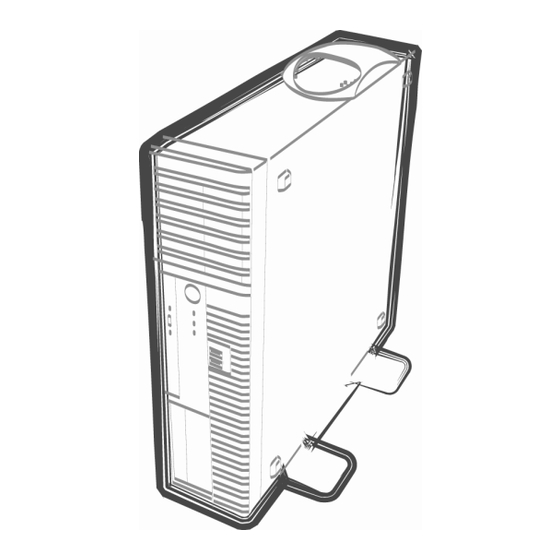
Chapter 1 General Description 4. Names and Functions of Parts Names and Functions of Parts Names and functions of parts are as follows. Front of the server 3.5-inch drive model Front Bezel removed (10) (11) (1) Vent Holes Cover (7) Front Bezel To take air to cool the server This cover protects the front part of the server. - Page 33 Chapter 1 General Description 4. Names and Functions of Parts 2.5-inch drive model (13) (12) (10) (11) (1) Vent Holes Cover (8) Stabilizer To take air to cool the server To mount the server vertically, install as shown in the image (2) POWER Switch (9) Bezel Lock Tabs (3 at side of Front Bezel) The switch to turn the server on and off.
-
Page 34: Rear View
Chapter 1 General Description 4. Names and Functions of Parts Rear view 3.5-inch drive model and 2.5-inch drive model (5) (4) (10) (13) (11) (11) (12) (1) AC Inlet (7) BMC RESET Switch This socket is used to connect the power cord. The switch to reset BMC of this server. -
Page 35: Internal View
Chapter 1 General Description 4. Names and Functions of Parts Internal view 3.5-inch drive model, air-cooled type (10) Power supply unit 3.5-inch Expansion Bay Cooling fan (CPU) Motherboard DIMM slots PCI slot 3.5-inch hard disk drive Cooling fan (rear) Optical disk drive (10) Cooling fan (bottom) Express5800/GT110e-S User’s Guide... - Page 36 Chapter 1 General Description 4. Names and Functions of Parts 3.5-inch drive model, liquid cooling type (12) (11) (10) Power supply unit Motherboard Liquid cooling unit (for cooling CPU) Cooling fan (front of radiator) DIMM slots Cooling fan (rear of radiator) 3.5-inch hard disk drive (10) Radiator Optical disk drive...
- Page 37 Chapter 1 General Description 4. Names and Functions of Parts 2.5-inch drive model, air-cooled type (3) (4) (11) (10) (12) Power supply unit Optical disk drive Cooling fan (CPU) 3.5-inch Expansion Bay DIMM slot Motherboard SAS backplane (10) PCI slot 2.5-inch hard disk drive (11) Cooling fan (rear) Cooling fan (HDD)
- Page 38 Chapter 1 General Description 4. Names and Functions of Parts 2.5-inch drive model, liquid cooling type (3) (4) (14) (13) (10) (11) (12) Power supply unit 3.5-inch Expansion Bay Liquid cooling unit (for cooling CPU) Motherboard DIMM slot (10) Cooling fan (front of radiator) SAS backplane (11) Cooling fan (rear of radiator) 2.5-inch hard disk drive...
-
Page 39: Motherboard
Chapter 1 General Description 4. Names and Functions of Parts Motherboard 3.5-inch drive model, 2.5-inch drive model (25) (21) (1)-2 (1)-4 (1)-1 (19) (1)-3 (24) (20) (12) (18)-1 (6)-0 (18)-2 (6)-1 (6)-2 (18)-3 (6)-3 (6)-4 (6)-5 (18)-4 (17) (13) (16) (15) (11) (10) (9) -
Page 40: Status Indicators
Chapter 1 General Description 4. Names and Functions of Parts Status Indicators This section explains the indication and meanings of the server LEDs. 3.5-inch drive model LINK/ACT POWER LED DISK Access LED STATUS LED Optical disk access LED SPEED LED Rear view Front view 2.5-inch drive model... -
Page 41: Power Led ( )
The following table lists STATUS LED patterns, their explanation and solution. Tips Refer to the system event log (SEL) by using NEC ESMPRO or the offline maintenance utility to view the cause of failure. STATUS LED pattern... -
Page 42: Disk Access Led ( )
Chapter 1 General Description 4. Names and Functions of Parts STATUS LED pattern Explanation Solution Failure of the power supply unit is detected Contact your sales representative. Flashing (amber) A fan alarm was detected. Check if the internal fan cable is properly connected. If the LED indication does not change when the fans are normal, contact your sales representative. -
Page 43: Speed Led ( 1, 2, M)
Chapter 1 General Description 4. Names and Functions of Parts 4.5.7 SPEED LED ( 1, This LED indicates which network interface is used. − The two LAN ports for data transmission support 1000BASE-T, 100BASE-TX, and 10BASE-T and the LED indicates which network interface is being used. •... -
Page 44: Chapter 2 Preparations
NEC Express5800 Series Express5800/GT110e-S Preparations This chapter describes preparations for using this server. 1. Installing Internal Optional Devices You can skip this section if you did not purchase any optional devices. 2. Installation and Connection You must place the server in an ideal location and connect some cables following this section. -
Page 45: Installing Internal Optional Devices
• Use only the devices and cables specified by NEC. You will be charged to repair damages, malfunctions, and failures caused by the use of any devices or cables not specified for use with this server even within the warranty period. -
Page 46: Anti-Static Measures
Chapter 2 Preparations 1. Installing Internal Optional Devices Anti-static Measures The server contains electronic components sensitive to static electricity. Avoid failures caused by static electricity when installing or removing any optional devices. • Wear a wrist strap (an arm belt or anti-static glove) Wear a wrist strap on your wrist. -
Page 47: Overview Of Installation And Removal
Chapter 2 Preparations 1. Installing Internal Optional Devices Overview of Installation and Removal Install/remove components by using the following procedure. If the server is ON, turn it off. Refer to Chapter 3 (6. Turning Off the Server). Disconnect the power cord from the outlet and the server. Disconnect all cables connected to the connector at the rear. -
Page 48: Removing The Side Cover
Chapter 2 Preparations 1. Installing Internal Optional Devices Removing the Side Cover Remove the side cover by using the following procedure. Refer to steps 1 to 3 in Chapter 2 (1.3 Overview of Installation and Removal) for preparations. Unlock the padlock attached to the chassis if applicable. -
Page 49: Removing The Front Bezel
Chapter 2 Preparations 1. Installing Internal Optional Devices Removing the Front Bezel Remove the front bezel by using the following procedure. Refer to steps 1 to 3 in Chapter 2 (1.3 Overview of Installation and Removal) for preparations. Release the three tabs on the front bezel () in the direction of the arrow shown in the image and then pull the front bezel forward slightly until it comes off the frame (). -
Page 50: Internal Flash Memory
Chapter 2 Preparations 1. Installing Internal Optional Devices Internal Flash Memory This section describes the procedure for installing the Internal Flash Memory. Internal Flash Memory connector Installation 1.6.1 Install the Internal Flash Memory in the following procedure. Refer to steps 1 to 5 in Chapter 2 (1.3 Overview of Installation and Removal) for preparations. Attach the Internal Flash Memory and fix it with the screw provided with this product. -
Page 51: Dimm
Up to 32 GB (8 GB × 4) of memory can be installed. Important • Use only the DIMMs specified by NEC. Installing a DIMM from a third party may cause the server to fail. (You will be charged to repair failures or damages caused by the use of such products even within the warranty period.) -
Page 52: Maximum Supported Memory Size
Chapter 2 Preparations 1. Installing Internal Optional Devices Maximum supported memory size 1.7.1 The maximum available memory size on the server depends on the architecture (x86 architecture) and OS specs. A list of maximum memory sizes The maximum memory size The maximum memory size supported on each OS supported on the server... -
Page 53: Installation
Chapter 2 Preparations 1. Installing Internal Optional Devices Installation 1.7.3 Install a DIMM by using the following procedure. Refer to steps 1 to 5 in Chapter 2 (1.3 Overview of Installation and Removal) for preparations. Hold the server with both hands and slowly and gently lay it so that the left side faces upward Rotate both levers of the target DIMM slot outward. -
Page 54: Removal
• When removing a defective DIMM, check error messages displayed at POST or NEC ESMPRO and check the DIMM slot where the defective DIMM is installed. • At least one DIMM needs to be installed for the server to operate. -
Page 55: Use Of Internal Hard Disk Drives In The Raid System
Chapter 2 Preparations 1. Installing Internal Optional Devices Use of Internal Hard Disk Drives in the RAID System This section describes how to use the Hard Disk Drives installed in the HDD cage at the front of the server in the RAID System. - Page 56 Chapter 2 Preparations 1. Installing Internal Optional Devices On-board SATA N8103- controller 128/149/150/151 Backplane for 2.5-inch Hard Disk Drives (Installed on 2.5-inch model as standard) When using on-board RAID Controllers (LSI Embedded MegaRAID Change jumper switch setting as shown below. Jumper pins on motherboard (SWRAID) Change jumper setting to 2-3 (Enabled).
- Page 57 Chapter 2 Preparations 1. Installing Internal Optional Devices After that, configure the RAID System using LSI Software RAID Configuration Utility. For details, refer to Chapter 2 (4. RAID System Configuration) in "Maintenance Guide". Tips If you use the EXPRESSBUILDER DVD supplied with the server for setup, the RAID System is automatically configured.
-
Page 58: Notes On Setting Up A Raid System
Chapter 2 Preparations 1. Installing Internal Optional Devices Installation For the instruction of installing the optional RAID Controller (N8103-128/149/150/151), refer to Chapter 2 (1.10 PCI Card). Important When connecting a RAID Controller, set the boot priority to 8th or higher in the Boot menu of the BIOS Setup utility. - Page 59 Chapter 2 Preparations 1. Installing Internal Optional Devices • The display of slot numbers (SLT) for Hard Disk Drives in the OS system event log varies depending on the RAID Controller to be connected. The tables below show the insert position of Hard Disk Drives and slot numbers (SLT). The information on these tables is important when checking logs or replacing a Hard Disk Drive.
- Page 60 Chapter 2 Preparations 1. Installing Internal Optional Devices The insert position number displayed on the server Models with 3.5-inch Hard Disk Drives installed Models with 2.5-inch Hard Disk Drives installed (standard) cage Models with 2.5-inch Hard Disk Drives installed (when expansion 2.5-inch HDD cages are installed) cage Express5800/GT110e-S User’s Guide...
-
Page 61: Extra Battery For Raid Controller
Chapter 2 Preparations 1. Installing Internal Optional Devices Extra Battery for RAID Controller If a RAID Controller (N8103-128/149/150/151) is installed, use the optional extra battery to avoid data loss caused by accidents including temporary blackout during a write-back operation. The model of the extra battery to be used depends on RAID Controller. - Page 62 Chapter 2 Preparations 1. Installing Internal Optional Devices Installing the battery in the server This section describes how to install an extra battery in the server. Note that the installation position and procedure differ for 2.5-inch Hard Disk Drive models and 3.5-inch Hard Disk Drive models. Start Preparation for installation Installing the connector board...
- Page 63 Chapter 2 Preparations 1. Installing Internal Optional Devices Installing a RAID Controller Install the RAID Controller into the PCI slot #1 of the server. RAID Controller Connecting the battery control cable Referring to the image below, connect the battery control cable into the battery pack. Check the orientation of the connector and connect the cable straight into the connector.
- Page 64 Chapter 2 Preparations 1. Installing Internal Optional Devices Installing a battery pack to 2.5-inch Hard Disk Drive models (1) Remove the file device or dummy cover. For the dummy cover, pull it toward you while pressing the tab on the right. (2) Remove the two screws from the blank cover.
- Page 65 Chapter 2 Preparations 1. Installing Internal Optional Devices (4) Engage the tabs of the bracket with the grille of the blank cover and fix it with the attached screw (large). Refer to the image below for the installation position. Installation position Engage the tab with the part second from left at the bottom.
- Page 66 Chapter 2 Preparations 1. Installing Internal Optional Devices (5) Engage the tabs at the lower part of the blank cover with the chassis and fix it with the two screws. If the cable is too long, arrange it neatly, such as by coiling it once within the chassis. This concludes the installation of the battery module in a 2.5-inch Hard Disk Drive model.
- Page 67 Chapter 2 Preparations 1. Installing Internal Optional Devices Installing a battery pack to 3.5-inch Hard Disk Drive models (1) Remove one screw from the blank cover and slide it to the side to release the blank cover. (2) Pass the bracket containing the battery and which is connected to the remote cable through the opening from which the blank cover was removed.
- Page 68 Chapter 2 Preparations 1. Installing Internal Optional Devices (4) While pushing the blank cover to the right, fix it with one screw. If the cable is too long, arrange it neatly, such as by coiling once within the chassis. This concludes the installation of the battery module in a 3.5-inch Hard Disk Drive model. Express5800/GT110e-S User’s Guide...
-
Page 69: 1.9.3 Installing N8103-153 Extra Battery
Chapter 2 Preparations 1. Installing Internal Optional Devices 1.9.3 Installing N8103-153 extra battery Install an extra battery in the server by using the following procedure. Note Read through the user’s guide supplied with the RAID Controller before installation. Filling out the date on the Set up date label Write down the installation date (year and month) on the Set up date label supplied with the extra battery. - Page 70 Chapter 2 Preparations 1. Installing Internal Optional Devices Installing the battery in the server This section describes how to install this product in the server. Note that the installation position and procedure differ for 2.5-inch Hard Disk Drive models and 3.5-inch Hard Disk Drive models. Start Preparation for installation Installing the connector board...
- Page 71 Chapter 2 Preparations 1. Installing Internal Optional Devices Installing a battery pack to 2.5-inch Hard Disk Drive models Remove the file device or dummy cover. For the dummy cover, pull it toward you while pressing the tab on the right. Remove the two screws from the blank cover.
- Page 72 Chapter 2 Preparations 1. Installing Internal Optional Devices (4) Engage the tabs of the bracket with the grille of the blank cover and fix it with the attached screw (large). Refer to the image below for the installation position. Installation position Engage the tab with the part second from left at the bottom.
- Page 73 Chapter 2 Preparations 1. Installing Internal Optional Devices Engage the tabs at the lower part of the blank cover with the chassis and fix it with the two screws. If the cable is too long, arrange it neatly, such as by coiling it once within the chassis. Express5800/GT110e-S User’s Guide...
- Page 74 Chapter 2 Preparations 1. Installing Internal Optional Devices Installing a battery pack to 3.5-inch Hard Disk Drive models Remove one screw from the blank cover and slide it to the side to release the blank cover. Engage the tabs of the bracket with the grille of the blank cover and fix it with the attached screw (large).
- Page 75 Chapter 2 Preparations 1. Installing Internal Optional Devices While pushing the blank cover to the right, fix it with one screw. If the cable is too long, arrange it neatly, such as by coiling once within the chassis. Express5800/GT110e-S User’s Guide...
- Page 76 Chapter 2 Preparations 1. Installing Internal Optional Devices Connecting to a RAID Controller (1) Connect another connector of the battery control cable to the connector board on the RAID Controller. Check the orientation of the connector and connect the cable straight into the connector.
-
Page 77: Removal
Chapter 2 Preparations 1. Installing Internal Optional Devices Install a RAID Controller into the PCI slot and fix it in place. Be careful not to disconnect any cables. RAID Controller Connect the cables and components that you removed earlier. Removal 1.9.4 For removing the extra battery for the RAID Controller, reverse the installation procedure. -
Page 78: Pci Card
Chapter 2 Preparations 1. Installing Internal Optional Devices 1.10 PCI Card This server provides four slots where PCI cards can be installed. Important • You must avoid static electricity to work with the procedure below. For details, refer to Chapter 2 (1.2 Anti-static Measures). •... -
Page 79: Notes
Chapter 2 Preparations 1. Installing Internal Optional Devices Notes 1.10.1 Read the following notes when installing or removing a PCI card. • Do not touch the terminals of cards and the leads of electronic components with your bare hand. Fingerprints and dust left on them cause the server to malfunction due to a connection failure or damage to the leads. -
Page 80: List Of Option Devices And Installation Slots
Chapter 2 Preparations 1. Installing Internal Optional Devices List of option devices and installation slots 1.10.2 3.5-inch Hard Disk Drive model/air-cooling system PCI EXPRESS PCI#1 PCI#2 PCI#3 PCI#4 32-bit/ Product PCI slot performance X4lane X4lane X16lane Model name Remarks 33 MHz name Slot size Low Profile... - Page 81 Chapter 2 Preparations 1. Installing Internal Optional Devices 2.5-inch Hard Disk Drive model/air-cooling system PCI EXPRESS PCI#1 PCI#2 PCI#3 PCI#4 32-bit/ Product PCI slot performance X4lane X4lane X16lane Model name Remarks 33 MHz name Slot size Low Profile PCI card type socket socket socket...
- Page 82 Chapter 2 Preparations 1. Installing Internal Optional Devices 2.5-inch Hard Disk Drive model/liquid cooling system PCI EXPRESS 2.0 PCI#1 PCI#2 PCI slot performance X4lane X4lane Product Model name Remarks Slot size Low Profile name PCI card type socket socket Available card size Up to167.6 mm (MD2) N8103-128 RAID Controller (128 MB, RAID 0/1)
-
Page 83: Installation
Chapter 2 Preparations 1. Installing Internal Optional Devices Installation 1.10.3 Install a PCI card to connect to a PCI slot by using the following procedure. Before installation, make sure the switch or jumper settings on the card are properly set according to the instruction manual supplied with the card if necessary. - Page 84 Chapter 2 Preparations 1. Installing Internal Optional Devices Orient the component side of the card toward the bottom of the server. When the rear panel of the card is firmly engaged with the spring, firmly press the card into the slot so that the component parts of the card securely connect to the slot.
-
Page 85: Configuration After Installing
Chapter 2 Preparations 1. Installing Internal Optional Devices Configuration after installing 1.10.4 Depending on the type of card installed, you might need to use a utility (the BIOS setup utility included with this server or a setup utility provided with the card) following installation to modify server settings. Follow the instructions in the manual provided with the card to specify the correct settings. -
Page 86: Installing The N8117-01A Extra Rs-232C Connector Kit
Chapter 2 Preparations 1. Installing Internal Optional Devices Installing the N8117-01A extra RS-232C connector kit 1.10.6 Install a PCI card to connect to the PCI slot by using the following procedure. For details, refer to the instruction manual supplied with the connector kit. Important The N8117-01A extra RS-232C connector kit contains two types of cables. - Page 87 Chapter 2 Preparations 1. Installing Internal Optional Devices Remove the expansion blank cover aligned with the slot where you are going to install a card. Important Keep the removed blank cover for future use. Make sure that you are properly inserting the bracket edge into the frame guide, and attach it securely.
- Page 88 Chapter 2 Preparations 1. Installing Internal Optional Devices Arrange the cable so as not to buffer other PCI cards, and connect to the COM connector used for internal connections in the motherboard. Refer to the following for the position of the COM connector for internal connections. Important •...
-
Page 89: Inch Hard Disk Drive
Up to 2 SATA Hard Disk Drives can be installed in the 3.5-inch Hard Disk Drive model. Important Use Hard Disk Drives specified by NEC. Installing a third-party Hard Disk Drive might cause a failure of the server and the Hard Disk Drive. You will be charged for maintenance for failures and damage caused by these products, even during the maintenance period. -
Page 90: Installation
Chapter 2 Preparations 1. Installing Internal Optional Devices Installation 1.11.1 Follow the procedure below to install the 3.5-inch Hard Disk Drive. Refer to the manual provided with the Hard Disk Drive before installation, and specify the settings of the Hard Disk Drive. Number of Location of the bay Serial ATA connector of the... - Page 91 Chapter 2 Preparations 1. Installing Internal Optional Devices If the 3.5-inch device is attached, remove the cable and then remove the device. For details, refer to Chapter 2 (1.14 Backup devices). Lift the rear part of the sub frame to remove the sub frame.
-
Page 92: Removal
Chapter 2 Preparations 1. Installing Internal Optional Devices Removal 1.11.2 You can remove the Hard Disk Drive by using the following procedure. Important If you dispose of the removed hard disk drive, follow instructrions described in Chapter 1 (1. Transfer, Movement, and Disposal) in “Maintenance Guide”. -
Page 93: Inch Hard Disk Drive
Drive in the expansion cage. Important Use Hard Disk Drives specified by NEC. Installing a third-party Hard Disk Drive might cause a failure of the server and the Hard Disk Drive. You will be charged for maintenance for failures and damage caused by these products, even during the maintenance period. -
Page 94: Installing An Expansion 2.5-Inch Hdd Cage
Chapter 2 Preparations 1. Installing Internal Optional Devices Installing an expansion 2.5-inch HDD cage 1.12.1 For 2.5-inch Hard Disk Drive models, you can install an additional two Hard Disk Drives by using a 2.5-inch HDD cage. Tips An expansion 2.5-inch HDD cage is only supported by air-cooled models. Install the 2.5-inch HDD cage for additional drives by using the following procedure. - Page 95 Chapter 2 Preparations 1. Installing Internal Optional Devices Push the HDD cage halfway in the server. Do not push the cage in completely as the cable has to be connected to the device. Connect the fan cable of the HDD cage to the motherboard.
-
Page 96: Installation
Hard Disk Drive into place () (It is locked when you hear a clicking sound.) Important Use Hard Disk Drives recommended by NEC. For details, consult with the store where you made your purchase or your maintenance service company. Note Refer to the image and confirm that the Hard Disk Drive (tray) is oriented correctly before insertion. -
Page 97: Removal
Chapter 2 Preparations 1. Installing Internal Optional Devices Removal 1.12.3 You can remove the Hard Disk Drive by using the following procedure. Important If you dispose of the removed hard disk drive, follow instructrions described in Chapter 1 (1. Transfer, Movement, and Disposal) in “Maintenance Guide”. -
Page 98: Optical Disk Drive
Procedures for replacing the standard optical disk drive with the optional internal DVD SuperMULTI drive are described below. Important Do not install a drive other than those specified by NEC. Replacing drives 1.13.1 Follow the procedure below to replace your drive with the optional internal DVD SuperMULTI drive. -
Page 99: Backup Devices
Chapter 2 Preparations 1. Installing Internal Optional Devices 1.14 Backup devices This server contains slots for the installation of backup devices, such as optical disk drives and magnetic tape drives. As a standard, there is one expansion slot. Tips Controller board options and internal cables might be required depending on the devices installed. -
Page 100: Installation
Chapter 2 Preparations 1. Installing Internal Optional Devices Installation 1.14.1 Install a backup device by using the following procedure. The procedure will be described, focusing on installing the USB file device option. Refer to Chapter 2 (1.3 Overview of Installation and Removal) for preparations. Remove the side cover and front bezel while referring to Chapter 2 (1.4 Removing the Side Cover and 1.5 Removing the Front Bezel). -
Page 101: Removal
Chapter 2 Preparations 1. Installing Internal Optional Devices Insert the backup device into chassis. Do not push the backup device in completely as the cable has to be connected to the device. Connect the interface cable and power cable to the installed 3.5-inch device. For more information, refer to Chapter 2 (1.15 Connecting cables). -
Page 102: Connecting Cables
Chapter 2 Preparations 1. Installing Internal Optional Devices 1.15 Connecting cables This section shows an example of internal device cable connection. Interface cables 1.15.1 This section describes the connection of interface cables. Tips The figure shown here primarily describes connections. For more information about the connectors on the motherboard, refer to Chapter 1 (5.4 Motherboard). - Page 103 Chapter 2 Preparations 1. Installing Internal Optional Devices • If a RAID Controller (N8103-128/149/151) has been added Connecting to a RAID Controller (N8103-128/149/151) requires a dedicated cable (K410-253(00)) for use with RAID Controllers. Install the Hard Disk Drives in order from the bottom. Power supply Second Hard Disk Drive...
- Page 104 Chapter 2 Preparations 1. Installing Internal Optional Devices Important • SAS Hard Disk Drives and SATA Hard Disk Drives cannot be combined. • About RAID LED cables The DISK access LED on the front of the equipment shows the access status of Hard Disk Drives that are connected to a RAID Controller.
- Page 105 Chapter 2 Preparations 1. Installing Internal Optional Devices For 2.5-inch Hard Disk Drive models • If a RAID Controller (N8103-128/149/150/151) has been added If SAS or SATA Hard Disk Drives are installed and used in a RAID System with a RAID Controller (N8103-128/149/150/151), the dedicated cable K410-180(00) is required.
- Page 106 Chapter 2 Preparations 1. Installing Internal Optional Devices (When 5 Hard Disk Drives are installed) Power supply unit Slot 2: Third Hard Disk Drive Slot 1: Second Hard Disk Drive Motherboard Slot 0: First Hard Disk Drive RAID Controller Optical disk drive (N8103-128/149/150/151) Extra battery (N8103-141/155) 2.5-inch expansion HDD cage...
- Page 107 Chapter 2 Preparations 1. Installing Internal Optional Devices (When 3 Hard Disk Drives are installed for onboard connection) Power supply unit Slot 2: Third Hard Disk Drive Slot 1: Second Hard Disk Drive Motherboard Slot 0: First Hard Disk Drive Optical disk drive SGPIO connector SATA1...
- Page 108 Chapter 2 Preparations 1. Installing Internal Optional Devices Connecting 3.5-inch devices You can mount USB devices (for internal connections) to 3.5-inch device bay. If mounting an internal USB device Use the dedicated internal USB cable K410-255(00). Power supply unit Motherboard Optical disk drive Internal USB connector...
-
Page 109: Power Cables
Chapter 2 Preparations 1. Installing Internal Optional Devices Power cables 1.15.2 The illustration below shows an example of connecting the power cables. Power cables other than those shown here are not used by the devices. For 3.5-inch Hard Disk Drive models Power supply unit... -
Page 110: Attaching The Front Bezel
Chapter 2 Preparations 1. Installing Internal Optional Devices 1.16 Attaching the Front Bezel You can attach the front bezel by reversing the removal procedure. Insert the three tabs on the lower part of the front bezel into the holes on the front of the server and then push the upper part of the front bezel toward the server to lock with release tabs. -
Page 111: Installing The Side Cover
Chapter 2 Preparations 1. Installing Internal Optional Devices 1.17 Installing the Side Cover You can attach the side cover by reversing the removal procedure. Make sure that hooks at both the top and bottom of the side cover are securely inserted in the holes on the server frame. -
Page 112: Installation And Connection
Chapter 2 Preparations 2. Installation and Connection Installation and Connection This section describes how to position the server and connect cables. Installation CAUTION Be sure to observe the following precautions to use of the server safely. Failure to observe the precautions may cause burns, injury, and property damage. For details, refer to Safety precautions in Precautions for Use. -
Page 113: Chapter 2 Preparations
Chapter 2 Preparations 2. Installation and Connection Do not install the server in an environment in which any of the following conditions apply: Installing the server in any of the following conditions will cause the server to malfunction. Places where corrosive gas is present (environments where there is sulfur vapor in the atmosphere), or places Place of drastic temperature change... -
Page 114: Preparation For Installation
Chapter 2 Preparations 2. Installation and Connection Preparation for installation 2.1.1 For vertical mounting For vertical use of the server, the stabilizer attached to the bottom of the server must be removed to change the orientation as instructed below. Also be sure to attach the vent holes cover for cooling on the top of the server. Removing/installing the stabilizer Removing the stabilizer Release the lock plate and slide it in the direction of the arrow to remove. - Page 115 Chapter 2 Preparations 2. Installation and Connection After attaching the stabilizers, set up the server as shown in the image. Installing the vent holes cover Tabs on the vent holes cover (4 tabs) Orient and insert the 4 tabs into the holes of the server.
-
Page 116: Connection
Chapter 2 Preparations 2. Installation and Connection Connection Connect peripheral devices to the server. Connectors that allow a variety of peripheral devices to be connected are provided at the front and rear of the server. Images on the following pages show the peripheral devices that can be connected in their standard state and their respective connector positions. -
Page 117: Interface Cables
• The connectors that are not explained here are not used. Do not connect anything to the connectors. • Be sure to use the display unit specified by NEC. The operation is not guaranteed if you install a display unit not specified by NEC. - Page 118 Chapter 2 Preparations 2. Installation and Connection <Front view> USB devices (such as a FD drive) <Rear view> Finally, connect the A device with serial provided power cord to interface an outlet. (such as a modem) Display unit Hub/Switching hub USB devices (such as a terminal adapter) Express5800/GT110e-S User’s Guide...
-
Page 119: Power Cord
Chapter 2 Preparations 2. Installation and Connection Power cord 2.2.2 Connect the provided power cord to the server. Tips • To connect the power cord to a UPS, connect it to the outlet provided at the rear of the UPS. For details, refer to the instruction manual supplied with the UPS •... -
Page 120: Chapter 3 Setup
NEC Express5800 Series Express5800/GT110e-S Setup This chapter describes how to set up the server. 1. Turning on the Server POST (Power-On Self-Test) is explained in this section. 2. System BIOS Setup You can customize BIOS settings by following the instructions in this section. -
Page 121: Turning On The Server
3. Press the POWER switch at the front of the server. The POWER LED is turned on green and after a while, the NEC logo appears on the display. While the NEC logo is being displayed, the self-diagnostic program (POST) runs and diagnoses the hardware. -
Page 122: Post
POST starts memory check. When the memory check is completed, some messages appear. As factory settings, the NEC logo appears on the screen during POST. 2. If the <Esc> key is pressed, the logo disappears and the details of POST are displayed. - Page 123 Chapter 3 Setup 1. Turning on the Server 4. After a while, the following message is displayed on the screen. Press <F2> SETUP, <F3> Internal Flash Memory, <F4> ROM Utility, <F12> Network By pressing the designated function key following messages, you can call the functions below upon completion of POST.
-
Page 124: Post Error Messages
Chapter 3 Setup 1. Turning on the Server POST Error Messages 1.1.2 When POST detects an error, it displays an error message on the screen or beeps for some errors. For descriptions of error messages, causes, and countermeasures, refer to "Maintenance Guide". Important Take notes on the messages displayed before consulting with your maintenance service company. -
Page 125: System Bios Setup
If you press the <F2> key at this time, SETUP runs and displays the Main menu upon completion of POST. (You can also press the <F2> key while the NEC logo appears to display the Main menu.) Express5800/GT110e-S User’s Guide... -
Page 126: Description On On-Screen Items And Key Usage
Chapter 3 Setup 2. System BIOS Setup Description on On-Screen Items and Key Usage This section shows display examples and how to control the key. Use the keyboard to work with the SETUP utility. Indicates the currently displayed menu Indicates the menu has submenus. - Page 127 Chapter 3 Setup 2. System BIOS Setup <F2> key If you press this key, the following window appears. If you select Yes, the previous parameter(s) are restored. Load Previous Values? [Yes] <F3> key If you press this key, the following window appears. If you select Yes, restore the parameters of the currently selected item to the default setting.
-
Page 128: Cases That Require Configuration
Boot → Bootup Numlock State Boot → Quite Boot → Disabled On/Off the function to display By pressing the <Esc> key, the NEC logo during POST prevent the display of the logo. Advanced → PCI Configuration → PCI Optional Install RAID Controller board... - Page 129 Chapter 3 Setup 2. System BIOS Setup Password If you have set a password, a message prompt you to enter password will be displayed from the next time. Enter password [ You can attempt password entry up to 3 times. If you entered a wrong password 3 times, operation stops. (You cannot operate further.) Turn off the power.
-
Page 130: Expressscope Engine 3
Chapter 3 Setup 3. EXPRESSSCOPE ENGINE 3 EXPRESSSCOPE ENGINE 3 Overview EXPRESSSCOPE Engine 3 provides a variety of features using BMC (Baseboard Management Controller), which is a system management LSI. EXPRESSSCOPE Engine 3 monitors the power unit, fans, temperature, and voltage of the server. If you have the management LAN port connected to the network, you can remotely perform the following over a web browser or SSH client: •... -
Page 131: Expressscope Engine 3 Network Configuration
2. If you press the <F4> key at this time, ROM utility starts upon completion of POST. You can also press the <F4> key while the NEC logo is being displayed to open the Off-line TOOL MENU screen. 3. The keyboard selection screen appears. Select your keyboard type. - Page 132 Chapter 3 Setup 3. EXPRESSSCOPE ENGINE 3 5. If Property is selected, the following screen is displayed. On this screen, specify whether to use DHCP and if DHCP is not used, configure IP Address/Subnet Mask. Tips If Shared BMC LAN is enabled, Web feature, remote media/KVM feature, or command line interface feature may be interrupted.
-
Page 133: Expressbuilder
RAID configuration to installation of applications. To use this feature, (Windows reinstallation) select Os installation in the menu after boot. Storage of software* Stores various bundled software (such as NEC ESMPRO Agent). Maintenance Diagnoses your server system. To use this feature, select Tool menu in the menu after boot. -
Page 134: Installing Software Components
Chapter 3 Setup 5. Installing Software Components Installing Software Components Continue to install software components such as OS. Refer to the instructions below. • Installation Guide (Windows) Express5800/GT110e-S User’s Guide... -
Page 135: Turning Off The Server
Chapter 3 Setup 6. Turning Off the Server Turning Off the Server Turn off the server by using the following procedure. If the power cord of the server is connected to a UPS, refer to the documentation supplied with the UPS or the documentation for the application controlling the UPS. 1. -
Page 136: Chapter 4 Appendix
NEC Express5800 Series Express5800/GT110e-S Appendix Specifications Interrupt Lines Express5800/GT110e-S User’s Guide... -
Page 137: Specifications
Chapter 4 Appendix 1. Specifications Specifications Air-cooling System Express5800/GT110e-S, EXP281A Product name N8100-1891F N8100-1892F Specifications on shipment 3.5-inch Hard Disk Drive model 2.5-inch Hard Disk Drive model ® ® ® ® ® ® ® ® Type Intel Pentium Intel Xeon... -
Page 138: Liquid Cooling System
Chapter 4 Appendix 1. Specifications Liquid cooling System Express5800/GT110e-S , EXP281A Product name N8100-1894F Specifications on shipment 2.5-inch Hard Disk Drive model ® ® Type Intel Xeon processor E3-1365Lv2 Clock/cache 3.30 GHz/3 MB No standard / (1) Standard / (maximum) ®... -
Page 139: Interrupt Lines
Chapter 4 Appendix 2. Interrupt Lines Interrupt Lines Interrupt lines are assigned as factory settings as shown below. Use this table as a reference when you add optional devices. • Interrupt lines As factory settings, interrupt lines are assigned as follows. Peripheral Device (Controller) Peripheral Device (Controller) System timer...
Need help?
Do you have a question about the N8100-1891F and is the answer not in the manual?
Questions and answers