Table of Contents
Advertisement
Quick Links
Advertisement
Table of Contents

Related Manuals for Oce VarioStream 7000 SINGLE


Summary of Contents for Oce VarioStream 7000 SINGLE
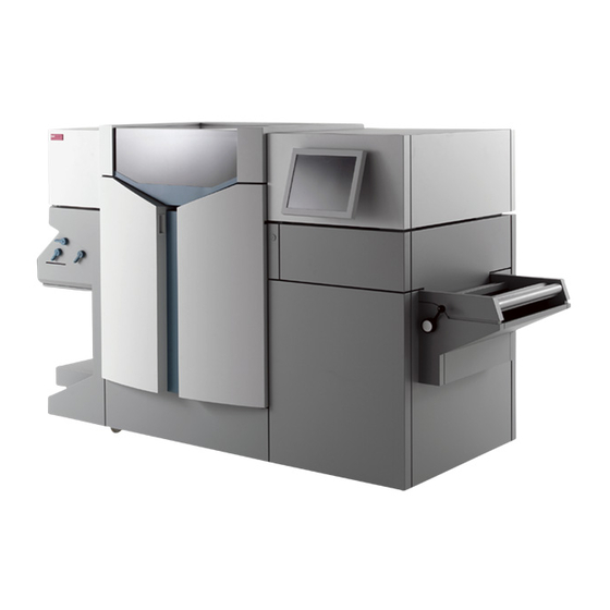
- Page 1 Océ | Operating Manual Océ Océ VarioStream 7000 SINGLE Pinfed...
- Page 2 ...and how about training? We also offer courses in our Training Center for the product described. Information: Phone +49 8121 72 3940 Fax +49 8121 72 3950 Océ Printing Systems GmbH Postfach 1260 85581 Poing Germany Edition 2005/11 Order no. A29246-X20-X-4-7680 Copyright ©...
- Page 3 Notes on the printing system documentation Safety Description of the printing system Operator panel Operating the printing system Cleaning the printing system Replacing consumables and expendables Correcting faults Appendix Index...
-
Page 5: Table Of Contents
Table of contents Table of contents Notes on the printing system documentation ........... 11 Overview........................11 Signposts ........................ 12 Using "Help" ......................13 1.3.1 Contents ....................14 1.3.2 Index ......................15 1.3.3 Search ...................... 16 1.3.4 Direct help ....................17 Symbols in the text .................... - Page 6 Table of contents 2.6.4 Transport ....................36 2.6.5 Repairs ..................... 36 2.6.6 Fire ......................36 2.6.7 Disposal ....................36 Safety regulations and standards ................37 2.7.1 CE Mark ....................38 2.7.2 Accident prevention regulations for the replacement cart for developer stations (optional) ..................
- Page 7 Table of contents 4.3.1.2 Deleting users ................82 4.3.1.3 Editing users ................82 4.3.2 Managing user settings (operator) ............84 4.3.2.1 Logging on as user and requesting the access ticket ....85 4.3.2.2 Changing password ..............86 4.3.2.3 Changing language ..............86 4.3.3 Setting parameters ...................
- Page 8 Table of contents 5.10 Converting the printing system ................162 5.10.1 Selecting a configuration ................ 164 5.10.2 Converting the printing system ............... 165 5.10.2.1 Start conversion ..............165 5.10.2.2 Replacing the toner feed ............166 5.10.2.3 Replacing the developer station ..........168 5.10.2.4 Replacing the photoconductor drum ........
- Page 9 Table of contents 7.3.1 Replacing the photoconductor drum ............. 257 7.3.2 Run in photoconductor drum ..............263 7.3.3 Replacing the cleaning brush ..............263 7.3.4 Replacing corotrons ................269 7.3.4.1 Preparing corotron replacement ..........270 7.3.4.2 Replacing the transfer corotron (1 cartridge) (pinfed) ..... 271 7.3.4.3 Replacing the transfer corotron (torn wire) (pinfed) ....
- Page 10 Table of contents Expendables for VarioStream 7200, VarioStream 7300, VarioStream 7400..361 Expendables for VarioStream 7450, VarioStream 7550, VarioStream 7650..362 Expendables for VarioStream 7450 CX, VarioStream 7550 CX, VarioStream 7650 CX ................364 Cleaning materials and equipment ................. 365 Technical data ........................
-
Page 11: Notes On The Printing System Documentation
1 Notes on the printing system documentation 1 Notes on the printing system documentation 1.1 Overview The purpose of this documentation is to ensure that all printing system-related work is car- ried out safely and correctly. It contains safety directives that must be strictly observed. Each section is divided into small, easy-to-understand subject areas. -
Page 12: Signposts
1.2 Signposts 1.2 Signposts This section 2 Safety gives you all necessary information on how to safely and efficiently operate the printing system. Section 3 Description of the printing system explains the structure of the printing system. The operational controls are also described. The section 4 Operator panel describes the individual areas of the operator panel with the most important icons and buttons. -
Page 13: Using "Help
1.3 Using "Help" 1.3 Using "Help" Help on the operator panel of the printing system is operated using the following buttons: Button Function opens Help. hides or displays the navigation area with the following tabs: • Contents(see section 1.3.1 Contents, page 14) •... -
Page 14: Contents
1.3.1 Contents 1.3.1 Contents The Help is divided into different main groups: • General • VarioPrint 5000 or VarioStream 9000 or VarioStream 7000 • Paper Path Manager • Paper post processing devices, if available In the "Contents" tab, you can show or hide individual Help levels and select the desired Help topic, e. -
Page 15: Index
1.3.2 Index 1.3.2 Index The "Index" tab provides quick access to the required information. You can also search directly for a specific word within index entries. Proceed as follows: Enter the text into the "Search" input field. Press Enter key. Example: A29246-X20-X-4-7680 / all102.fm... -
Page 16: Search
1.3.3 Search 1.3.3 Search Via the "Search" tab you can launch the full text search. The full text search is used to find one or more specific words in the entire Help. Uppercase or lowercase is not relevant for the search. Proceed as follows: Enter the text into the "Search"... -
Page 17: Direct Help
1.3.4 Direct help 1.3.4 Direct help Context-sensitive Direct Help provides detailed information on all: • Menus • Operating elements in menus • Error messages and warnings If necessary, all the requirements for a setting are also listed in the context-sensitive help system. - Page 18 1.3.4 Direct help Proceed as follows: Press the F1 key. The Direct Help is opened, e. g.: 2 of 2 A29246-X20-X-4-7680 / all102.fm...
-
Page 19: Symbols In The Text
1.4 Symbols in the text 1.4 Symbols in the text Different symbols help you to find your way around the text: Symbol Meaning Menu <Sample> The name of a button or menu on the operator panel is enclosed in angle brackets. SAMPLE button Mechanical buttons are denoted in uppercase letters. -
Page 20: Symbols In Diagrams And Illustrations
1.5 Symbols in diagrams and illustrations 1.5 Symbols in diagrams and illustrations If not otherwise indicated, diagrams and illustrations of actions depict the starting position of the respective component for the described step. For easier understanding, the diagrams only depict the components that are directly rele- vant to the immediate context. - Page 21 1.5 Symbols in diagrams and illustrations Symbol Meaning White arrow: Note arrow An action should be performed in this area, e. g.: A29246-X20-X-4-7680 / all102.fm...
-
Page 22: Other Documents
1.6 Other documents 1.6 Other documents If not otherwise indicated, the following documents are supplied with each printing system in addition to the operating manual: Title Order number Safety Information on Océ Printing Systems A29246-X23-X-1-79 Papierspezifikation Endlos-Drucksysteme Deutsch: A29249-X2-X-10-59 Paper Specification Continuous Feed Printing English: A29249-X2-X-10-7659 Systems (English) 1.7 Manufacturer of the printing system... -
Page 23: Statutory Requirements
1.8 Statutory requirements 1.8 Statutory requirements The information, data and instructions in this documentation were up-to-date at the time of going to press. The right of technical modifications due to further development of the print- ing system is reserved. For this reason, the information, illustrations and descriptions in this documentation cannot give rise to any claims for modifications or additions to printing sys- tems that have already been shipped and accepted. - Page 24 1.8 Statutory requirements A29246-X20-X-4-7680 / all103.fm...
-
Page 25: Safety
2 Safety 2 Safety 2.1 Overview This section gives you all necessary information on how to safely and efficiently operate the printing system. You will find information on the following topics: 2.2 Intended Purpose >>> page 26 2.3 Operating and service clearance areas >>> page 27 2.4 Flagging of safety directives >>>... -
Page 26: Intended Purpose
2.2 Intended Purpose 2.2 Intended Purpose The printing system shall only be considered as being used for its intended purpose if the notices and instructions in this documentation are strictly observed. The printing system is intended solely for printing materials that comply with the paper specifications (see section 1.6 Other documents, page 22). -
Page 27: Operating And Service Clearance Areas
2.3 Operating and service clearance areas 2.3 Operating and service clearance areas The operating and service clearance areas for the printing system depicted in the following diagram should not be obstructed in any way. Dotted lines: additional area required for replacing the developer station Dimensions in millimeters (inches) A29246-X20-X-4-7680 / fa202_single.fm... -
Page 28: Flagging Of Safety Directives
2.4 Flagging of safety directives 2.4 Flagging of safety directives In addition to the safety directives in section 2.6 Accident and damage prevention, you must also observe the safety directives outlined elsewhere in this documentation . The following notational conventions are used for the safety directives in the text of the manual: Alert word Icon... -
Page 29: Warning And Information Signs
2.5 Warning and Information signs 2.5 Warning and Information signs The following signs are affixed inside the printing system at potential danger points: Sign Meaning Warning: Live electric parts There are live electric parts behind protective covers bearing this sign. These protective covers may only be removed by authorized Océ... - Page 30 2.5 Warning and Information signs Sign Meaning Do not touch the photoconductor drum surface. When working with the photoconductor drum, never touch its surface. Only touch the PC drum on the inside. When working with the photoconductor drum, only hold it on the inside. Disposal The symbol "the crossed-out wheeled bin"...
-
Page 31: Accident And Damage Prevention
2.6 Accident and damage prevention 2.6 Accident and damage prevention This section contains information on the following topics: 2.6.1 Personal Representations >>> page 31 2.6.2 Operation >>> page 32 2.6.3 Assembly and installation >>> page 35 2.6.4 Transport >>> page 36 2.6.5 Repairs >>>... -
Page 32: Operation
2.6.2 Operation Service Service staff are specialized Océ personnel who carry out all work that operators do not have the permission to, on and with the printing system. (e. g., any work on the power cir- cuits in the printing system). 2.6.2 Operation Observe the following instructions when operating the printing system: 2.6.2.1 Operator >>>... -
Page 33: Safety Covers
2.6.2.2 Safety covers • Do not work with unprotected long hair or wear loosely hanging items of clothing (e. g. ties, sleeves, scarves et. c.), or jewelry such as necklaces, bracelets and rings, since these can catch in the drive mechanisms or moving parts of the printing system and cause injury. -
Page 34: Cooling, Heat, Emissions
2.6.2.5 Cooling, heat, emissions • Should the printing system emit any unusual or noticeable noises or smells, power down the printing system and contact your service engineer. 2.6.2.5 Cooling, heat, emissions • Do not obstruct the cooling ducts, since this may result in overheating or combustion while the device is in operation. -
Page 35: Laser
2.6.2.8 Laser 2.6.2.8 Laser • If the printing system contains a laser: Never look directly into a laser beam or laser optics. Never move a tool near the laser beam so that you do not unintentionally divert the laser beam. The laser beams in fiber optic devices can injure your eyes. -
Page 36: Transport
2.6.4 Transport • Data transmission lines should neither be connected nor disconnected during electrical storms. 2.6.4 Transport The printing system may only be transported by service personnel or authorized transport companies. 2.6.5 Repairs Repairs to the device must only be carried out by service personnel. Access to locked areas and areas which can only be opened with special tools is reserved for service personnel. -
Page 37: Safety Regulations And Standards
2.7 Safety regulations and standards • Points to observe when disposing of a photoconductor drum: – Before touching the drum, always put on the gloves provided with the drum. – Should the photosensitive coating on the drum flake off, carefully collect the flakes or fragments of coating. -
Page 38: Ce Mark
2.7.1 CE Mark 2.7.1 CE Mark The printing system fulfills the requirements of the EC directives 89/336/EWG, "Electro- magnetic Compatibility" and 73/23/EWG "Low Voltage Directive". The CE Mark indicates that the printing system complies with these EC directives. The replacement cart for developer stations (optional) is also CE certified. All other devices that are connected to the printing system must also comply with the requirements set forth in the relevant EC directives. - Page 39 2.7.2 Accident prevention regulations for the replacement cart for developer stations (optional) Records must be kept of the results of device inspections as per §23. Proof of these inspec- tions as per § 23 par. 1 and 2 can be provided e. g. by entering the inspection results in an inspection log, by maintaining a file index or by affixing a test badge (giving inspection date and inspection office).
- Page 40 2.7.2 Accident prevention regulations for the replacement cart for developer stations (optional) A29246-X20-X-4-7680 / all203.fm...
-
Page 41: Description Of The Printing System
3 Description of the printing system 3 Description of the printing system 3.1 Overview This section presents the printing system structure graphically. The operating elements are also described. You will also find information on paper types, paper handling and toner bottle identification. -
Page 42: Doors And Covers
3.2.1 Doors and covers 3.2.1 Doors and covers Front view Side door of fuser station Front door of fuser station Left door Right door A29246-X20-X-4-7680 / fa301.fm... - Page 43 3.2.1 Doors and covers Front door of fuser station Cover hood Left door Right door A29246-X20-X-4-7680 / fa301.fm...
- Page 44 3.2.1 Doors and covers Rear view Left door Right door Center door A29246-X20-X-4-7680 / fa301.fm...
-
Page 45: Internal View
3.2.2 Internal view 3.2.2 Internal view Front side 9 10 11 A29246-X20-X-4-7680 / fa301.fm... - Page 46 3.2.2 Internal view 1 side door of fuser station 11 Operator panel on paper transporter 2 Stacker operator panel 12 Touchscreen operator panel 3 Fuser station 13 Floppy disk drive 4 Front door of fuser station 14 Charge corotron cartridges 5 Paper transporter 15 Front right door 6 Cover hood...
- Page 47 3.2.2 Internal view Rear 1 Back left door 2 Fuser oil container 3 Back center door 4 Fuser station 5 Back right door 6 Container for toner supply bottle 7 Container for fine filter 8 Toner dust indicator 9 Container for waste toner bottle 10 Main circuit breaker A29246-X20-X-4-7680 / fa301.fm...
-
Page 48: Toner Bottle Identification
3.2.3 Toner bottle identification 3.2.3 Toner bottle identification Toner bottle identification ensures that the toner bottle and toner box are assigned correctly and unambiguously to the developer station. A plausibility check also prevents incorrect settings on the developer station. For this purpose, each toner bottle is equipped with a transponder for toner identification. Transponder data is read by a reader and this information is analyzed by the printing system. - Page 49 3.2.3 Toner bottle identification The most important toner data and the current fill level can be found in the operator panel in menu <Replace consumables> <Toner bottle identification>, e. g.: Display Description Toner Displays the ID of the toner used. The message "unknown"...
-
Page 50: Operating Elements
3.3 Operating elements 3.3 Operating elements This section contains information on the following topics: 3.3.1 Operator panel on paper transporter >>> page 50 3.3.2 Stacker operator panel >>> page 51 3.3.1 Operator panel on paper transporter This operator panel can be accessed by opening the printing system cover hood. It has three keys for moving the paper web. -
Page 51: Stacker Operator Panel
3.3.2 Stacker operator panel 3.3.2 Stacker operator panel The stacker is only available as an option for the printing system. 1 Stacker operator panel 2 Stacker A29246-X20-X-4-7680 / fa301.fm... - Page 52 3.3.2 Stacker operator panel Stacker operator panel Pos. Key Function READY Switches the printing system from "Stop" or "Error" modes to ready mode. If no error condition is present, the green indicator lamp lights up. Requirements: • No errors present •...
- Page 53 3.3.2 Stacker operator panel Pos. Key Function switches on the tension rollers in the stacker top. Pressing the key again deactivates them. After a period of 10 seconds, the tension rollers are automatically powered down (not while paper is being inserted). This key has no function during the preparation phase of the printing system.
- Page 54 3.3.2 Stacker operator panel LED display Pos. Indicator lamp Function READY This green indicator lamp lights up if no error condition is present when the READY key is pressed. EJECT The yellow indicator lamp lights up while the paper is being advanced after pressing the EJECT or NPRO keys.
-
Page 55: Paper Specifications
3.4 Paper specifications 3.4 Paper specifications Note When using continuous rollpaper, observe the operating instructions for the paper pre- and post-processing devices. This section contains information on the following topics: 3.4.1 General information >>> page 55 3.4.2 Paper types >>> page 55 3.4.3 Paper handling >>>... -
Page 56: Paper Handling
3.4.3 Paper handling 3.4.3 Paper handling The climate (temperature and relative humidity) in the storeroom or processing room is of major importance in ensuring optimum paper processing. Unsuitable conditions can, for example, give the paper an excessive curl, make it bumpy, or alter its electrical resistance. The paper should be transported and stored in a suitable manner. -
Page 57: Paper Feed Options
3.5 Paper feed options 3.5 Paper feed options 1 Photoconductor drum 2 LED print head 3 External paper feed 4 Paper feed from behind 5 Internal input tray 6 Paper feed from the front A29246-X20-X-4-7680 / fa301.fm... - Page 58 3.5 Paper feed options A29246-X20-X-4-7680 / fa301.fm...
-
Page 59: Operator Panel
4 Operator panel 4 Operator panel 4.1 Overview This section describes the individual areas of the operator panel with the most important icons and buttons. You will also find out how to navigate through the menus, set parameters, and start and end the replacement of consumables and expendables. You will find information on the following topics: 4.2 Operator panel description >>>... -
Page 60: Operator Panel Description
4.2 Operator panel description 4.2 Operator panel description The operator panel is divided into the following areas: 1 see section 4.2.1 Toolbar, page 61 2 see section 4.2.2 Menu tree, page 71 3 see section 4.2.3 Menu display, page 79 A29246-X20-X-4-7680 / fa400.fm... -
Page 61: Toolbar
4.2.1 Toolbar 4.2.1 Toolbar The toolbar can be used to access important functions in the printing system quickly and to switch directly to frequently used menus. 1 see section 4.2.1.1 Buttons and displays in the left-hand area, page 62 2 see section 4.2.1.2 Center area buttons and displays, page 64 3 see section 4.2.1.3 Frame toolbar, page 69 A29246-X20-X-4-7680 / fa400.fm... -
Page 62: Buttons And Displays In The Left-Hand Area
4.2.1.1 Buttons and displays in the left-hand area 4.2.1.1 Buttons and displays in the left-hand area Note The following buttons can be operated both with the mouse and from the touchscreen. Button Function switches the printing system back from "Stop" or "Error" status to operational status. - Page 63 4.2.1.1 Buttons and displays in the left-hand area Display Function Standard display (no current print data from the host). Indicates that the controller is performing a restart. If this message is displayed, print data transfer from the host must be repeated as it cannot be guaranteed that the last pages were correctly transferred and fused before the error occurred.
-
Page 64: Center Area Buttons And Displays
4.2.1.2 Center area buttons and displays 4.2.1.2 Center area buttons and displays The current printer status is displayed in the center area of the toolbar. The individual displays have different background colors depending on the printer status: • Green: the printer is printing or is ready to print •... - Page 65 4.2.1.2 Center area buttons and displays Display Function The printing system is switching to "Stop" status. The printing system is being initialized and is not yet ready for printing. The printing system is stopping to clean the corotrons. The printing system is being prepared for power off.
- Page 66 4.2.1.2 Center area buttons and displays Display Function The printing system is in "Stop" status. The following icon is displayed when a message from the data stream has also been transferred: The complete message is displayed on the "Job Preparation" tab in the <Setup> menu. The printing system is being prepared for restart and will then be rebooted.
- Page 67 4.2.1.2 Center area buttons and displays Button Function Switches to the <Emulations> menu. The following buttons are available here under "Job control": Cancels the current print job. The data in the page buffer is erased. Requirement: The printing system is in "Stop" status.
- Page 68 4.2.1.2 Center area buttons and displays Button Function Activates the channel. The clutch icon is closed. Deactivates the channel. The clutch icon is opened. During the time needed to activate/deactivate a channel, the clutch icon is shown in yellow. Flashes when there is an error message. Flashes when there is a warning.
-
Page 69: Frame Toolbar
4.2.1.3 Frame toolbar Button Function Indicates that remote access is not activated. Clicking the button activates remote access directly without having to go through the menu. Switches to the <Consumables counter> menu. This menu displays the current counter values and the respective limit values for all consumables and expendables in the printing system. - Page 70 4.2.1.3 Frame toolbar Button Function Switches to the <Change user> menu. Users can be logged on and off in this menu. Displays the user currently logged on. Powers down the printing system if the print is confirmed. This button can be operated both with the mouse and from the touchscreen.
-
Page 71: Menu Tree
4.2.2 Menu tree 4.2.2 Menu tree All the menus can be accessed via the menu tree. The menus are structured into main groups, e. g.: • [00] <General> You can define the user settings valid for the entire printing system in these menus. •... - Page 72 4.2.2 Menu tree You can switch directly to the main menu from any menu. Click the following button in the toolbar for this purpose: Note The menus displayed in the menu tree depend on the respective authorizations for the individual user categories. This documentation describes all menu options set up as default for the user categories "Operator"...
-
Page 73: Menus
4.2.2.1 Menus <General> 4.2.2.1 Menus <General> Note Menus that can only be opened by the user "Key operator" as standard are shown in italics in the table. Menu Description General The sub-menus contain global settings for users, access tickets and screen cleaning for the entire printing system User management The sub-menus contain the user settings relating to... -
Page 74: Menus
4.2.2.2 Menus<VarioStream> 4.2.2.2 Menus<VarioStream> Menu Description <VarioStream> Displays basic information on the printing system: • Number of all 12" pages previously printed in user operation. • Setup currently loaded • Current print job • Name and serial number of the printing system •... - Page 75 4.2.2.2 Menus<VarioStream> Menu Description <Printing system> The sub-menus contain specific parameters for the printing system <Speed> Select printer speed <Paper path> Settings for paper brakes, automatic paper ejection and paper end <Stacker> Settings for stacker properties <Operating mode> Select operating mode <System functions>...
- Page 76 4.2.2.2 Menus<VarioStream> Menu Description <Standard resources> Select and display standard resources for I- Mode <Resource management> Install new resources or delete existing resources <PCL mode> The sub-menus contain the parameters for PCL mode <Properties> Settings for job separation, alignment, print mode, number of copies and lines per forms overlay <Continuous feed>...
- Page 77 4.2.2.2 Menus<VarioStream> Menu Description <Remote diagnostics> Activate or deactivate remote access by the service <Setup> Display and edit the globally valid print job setups <Setup channel A / B / C> Display and edit setups for channel A <Setup channel A / B / C> Display and edit setups for channel B <Setup channel A / B / C>...
-
Page 78: Menus
4.2.2.3 Menus <Paper Path Manager> 4.2.2.3 Menus <Paper Path Manager> Note You can find information on the Paper Path Manager in the printing system operator panel in Help. A29246-X20-X-4-7680 / fa400.fm... -
Page 79: Menu Display
4.2.3 Menu display 4.2.3 Menu display This area shows the menu selected in the menu tree. You can select or set all parameters required to operate the printing system here. Note Detailed information on all menus and operating elements is also available directly in the operator panel via the context-sensitive Direct Help. -
Page 80: Using The Operator Panel
4.3 Using the operator panel 4.3 Using the operator panel This section contains information on the following topics: 4.3.1 Managing user settings (key operator) >>> page 81 4.3.2 Managing user settings (operator) >>> page 84 4.3.3 Setting parameters >>> page 87 4.3.4 Starting and completing the replacement of consumables and expendables >>>... -
Page 81: Managing User Settings (Key Operator)
4.3.1 Managing user settings (key operator) 4.3.1 Managing user settings (key operator) As a key operator, you can normally make the following user settings: 4.3.1.1 Adding users >>> page 81 4.3.1.2 Deleting users >>> page 82 4.3.1.3 Editing users >>> page 82 Note A logged-on user can only create, delete or edit users who have a lower authorization level. -
Page 82: Deleting Users
4.3.1.2 Deleting users 4.3.1.2 Deleting users Proceed as follows: Click the <General> <User management> <Delete user> menu. Select user: • If a whole user group is to be deleted: select the entry "Template" under "Type" select the desired template under "Name." •... - Page 83 4.3.1.3 Editing users Setting passwords and authorization levels for users Proceed as follows: Click on the "General" tab. Enter the password and re-enter it identically under "Password confirmation". The password may consist of any characters. Set authorization level. Authorization levels can only be changed to one level below that of the person editing the level.
-
Page 84: Managing User Settings (Operator)
4.3.2 Managing user settings (operator) Presetting language for users Proceed as follows: Click on the "User Profile" tab. Select the desired language in the selection list. Click on the following button: 4.3.2 Managing user settings (operator) As an operator, you can normally make the following user settings: 4.3.2.1 Logging on as user and requesting the access ticket >>>... -
Page 85: Logging On As User And Requesting The Access Ticket
4.3.2.1 Logging on as user and requesting the access ticket 4.3.2.1 Logging on as user and requesting the access ticket To be able to set parameters on the operator panel, you must first log on as a user and then request the access ticket. -
Page 86: Changing Password
4.3.2.2 Changing password 4.3.2.2 Changing password Proceed as follows: Click the <General> <User> <User profile> menu. Click on the "Password" tab. Enter the old password and then enter the new password twice. The password may consist of any characters. Click on the following button: 4.3.2.3 Changing language Proceed as follows: Click the <General>... -
Page 87: Setting Parameters
4.3.3 Setting parameters 4.3.3 Setting parameters All parameters of the printing system can be set at the operator panel. The following prerequisites must be given: • The necessary rights are available. These rights are allocated by the respective "Key Operator" in the <Edit user> menu (see section 4.3.1.3 Editing users, page 82). •... -
Page 88: Selecting Settings And Entering Values
4.3.3.1 Selecting settings and entering values 4.3.3.1 Selecting settings and entering values You can select predefined settings and values through various operating elements, such as selection lists, option fields, checkboxes, slide controls, etc. You can also enter new values in input fields via the keyboard. Example: Entering the paper length Proceed as follows: Select unit for paper length... -
Page 89: Apply Or Reset Parameters
4.3.3.2 Apply or reset parameters 4.3.3.2 Apply or reset parameters If you change parameters in a menu, you have to confirm these changes before switching to another menu. Button Function The parameters are applied. The parameters are not applied; instead the previous parameters are restored. -
Page 90: Starting And Completing The Replacement Of Consumables And Expendables
4.3.4 Starting and completing the replacement of consumables and expendables 4.3.4 Starting and completing the replacement of consumables and expendables The operator panel informs you about the current status of the printing system. Warning and error messages indicate when consumables or expendables (= consumables/ expendables) have to be refilled or replaced. - Page 91 4.3.4 Starting and completing the replacement of consumables and expendables Requirements: • the user rights for replacing the developer are available • the access ticket for this operator field is requested • the printing system is in "Stop" or "Error" status, i.e. does not print •...
- Page 92 4.3.4 Starting and completing the replacement of consumables and expendables Proceed as follows: Click on the <Replace consumables> <Replace cleaning brush> menu. A menu window is opened, which displays all the necessary steps, e. g.: 1 of 3 A29246-X20-X-4-7680 / fa405.fm...
- Page 93 4.3.4 Starting and completing the replacement of consumables and expendables Proceed as follows: Perform all the displayed steps in the given order. Icons The icons on the left-hand side show the type of the current step: Answer a query at the operator panel. Perform a mechanical adjustment of the printing system.
- Page 94 4.3.4 Starting and completing the replacement of consumables and expendables Proceed as follows: Complete replacement procedure. As a result, the following will occur automatically: • the message on the operator panel is deleted • the replacement of the consumable/expendable is documented in the <Consumables history>...
-
Page 95: Operating The Printing System
5 Operating the printing system 5 Operating the printing system 5.1 Overview This section explains how to power the printing system on and off and the procedure for inserting, removing and replacing the paper web. You will find information on the following topics: 5.2 Powering on the printing system >>>... -
Page 96: Powering On The Printing System
5.2 Powering on the printing system 5.2 Powering on the printing system Note If the optional High Temperature Kit is used, the external recooling system must be powered on before powering on the printing system: Proceed as follows: Turn the main circuit breaker on the right narrow side upwards to Position I. - Page 97 5.2 Powering on the printing system Proceed as follows: Only if an SRA boot error appears in the operator panel or when rebooting is required. The printing system is initialized (takes approx. 6 minutes). The printing system's current status information is displayed on the operator panel. Activate the desired channel on the operator panel.
- Page 98 5.2 Powering on the printing system Proceed as follows: Click on the following button: The printing system is in "Ready" status. 3 of 3 A29246-X20-X-4-7680 / fa501.fm...
-
Page 99: After Print Stop, Switch The Printing System Back To "Ready
5.3 After print stop, switch the printing system back to "Ready" 5.3 After print stop, switch the printing system back to "Ready" A print stop may have the following causes: • The controller has run out of data. The printing system is in "Ready" status and continues printing automatically as soon as print data is available again. -
Page 100: Inserting Paper (Pinfed)
5.4 Inserting paper (pinfed) 5.4 Inserting paper (pinfed) To insert paper, the printing system must be powered on, i.e. the main circuit breaker is in position I and the POWER ON key is activated. The paper can be fed either via the internal input tray or via the external central paper feed. - Page 101 5.4 Inserting paper (pinfed) Proceed as follows: Click on the following button: The cut paper web is placed in the stacker. Remove paper stack from the input tray. If the paper changes, perform the corresponding actions (see section 5.6 Settings when changing paper (pinfed), page 121).
- Page 102 5.4 Inserting paper (pinfed) Proceed as follows: Only for paper feed via the internal input tray: Insert the new paper stack in the input tray so that the paper points to the right, i.e. the first paper fold is to the left.
- Page 103 5.4 Inserting paper (pinfed) Proceed as follows: Only for external paper feed: Pull out the external paper feed lever and turn to the right to the stop point. 13. Position the start of the paper web with the fold line to the front between the guide washers.
- Page 104 5.4 Inserting paper (pinfed) Proceed as follows: Only if the paper width has changed: Move the right guide washer so that the paper has some space to run between the two guide washers. Guide the paper between the tension rollers and push into the printing system by hand.
- Page 105 5.4 Inserting paper (pinfed) Proceed as follows: 16. Continue to push in paper by hand until a few pages are in the printing system. If the paper jams, open the front left door and pull the paper into the printing system by hand.
-
Page 106: Semi-Automatic Paper Insertion
5.4.1 Semi-automatic paper insertion 5.4.1 Semi-automatic paper insertion With some printing systems, the preheating saddle is not heated and does not have a cover. The following diagrams illustrate the printing systems with heated preheating saddles and covers. Proceed as follows: Turn the handle to the left and push the rocker downwards. - Page 107 5.4.1 Semi-automatic paper insertion Proceed as follows: Open the two lower tractor doors. Only for external paper feed: Guide the paper through the swing as shown. A29246-X20-X-4-7680 / fa502_pinfed.fm...
- Page 108 5.4.1 Semi-automatic paper insertion Proceed as follows: Hold the left of the paper web by the first fold and with the first and second page folded up (i.e. with the first fold to the right, the first page lies underneath) push it into the paper transporter until the fold lies in the area of the upper tractors.
- Page 109 5.4.1 Semi-automatic paper insertion Proceed as follows: Only if changing the paper width: Adjust the rear tractors with the turning knob so that the pins are in the tractor holes. The paper should not be tightly tensioned. Close the rear tractor door. Swivel the rocker upwards.
- Page 110 5.4.1 Semi-automatic paper insertion Proceed as follows: Only for printing systems with heated preheating saddle: When the front edge of the paper has disappeared under the cover of the preheating saddle, swivel the lever to the right. The lower tractor doors are now closed.
- Page 111 5.4.1 Semi-automatic paper insertion Proceed as follows: 14. Press the EJECT key briefly. The paper is now automatically transported through the fuser station to the stacker and placed there in the correct order. An automatic cleaning phase is now performed. The message "Cleaning cycle underway"...
-
Page 112: Manual Paper Insertion After A Paper Jam
5.4.2 Manual paper insertion after a paper jam 5.4.2 Manual paper insertion after a paper jam Proceed as follows: Turn the knob to the left and push the rocker downwards. Open the two upper tractor doors. Swivel the lever to the left. A29246-X20-X-4-7680 / fa502_pinfed.fm... - Page 113 5.4.2 Manual paper insertion after a paper jam Proceed as follows: Open the two lower tractor doors. Lower the stacker top by pressing the key. Only for printing systems with heated preheating saddle: Open cover above the preheating saddle. A29246-X20-X-4-7680 / fa502_pinfed.fm...
- Page 114 5.4.2 Manual paper insertion after a paper jam Proceed as follows: Cut paper in the input tray in the paper stack area or at a negative (>) fold for an external paper feed. Remove paper from the entire paper path, including jammed paper, from the stacker and the fuser station.
- Page 115 5.4.2 Manual paper insertion after a paper jam Proceed as follows: Hold the paper to the left at the first fold and with the first and second page folded up (i.e. with the first fold to the right, first page underneath) push it into the paper transporter.
- Page 116 5.4.2 Manual paper insertion after a paper jam Proceed as follows: Insert the paper web in the upper tractors in such a way that the pins protrude from the paper tractor holes. Close both tractor doors. Swivel the rocker upwards. The paper is now automatically advanced.
- Page 117 5.4.2 Manual paper insertion after a paper jam Proceed as follows: Place the lever for the distance of the tension rollers in the OFF position. Push the paper web through the stacker top and place in stacker. A29246-X20-X-4-7680 / fa502_pinfed.fm...
- Page 118 5.4.2 Manual paper insertion after a paper jam Proceed as follows: Return the lever for the distance of the tension rollers to the NORMAL position. Only for printing systems with heated preheating saddle: Close cover above the preheating saddle. 19. An automatic cleaning phase is now performed. The message "Cleaning cycle underway"...
- Page 119 5.4.2 Manual paper insertion after a paper jam Proceed as follows: 21. Click on the following button: The "Check paper position" message is displayed in the P mode in the operator panel. 22. Click on the following button again: 23. Close the doors on the front of the printing system. 24.
-
Page 120: Setting The External Paper Feed Lever
5.5 Setting the external paper feed lever 5.5 Setting the external paper feed lever The optimum position of the external feed lever can only be determined during printing. The deflection of the swing in the printing system indicates whether and how far the lever needs to be turned to the left. -
Page 121: Settings When Changing Paper (Pinfed)
5.6 Settings when changing paper (pinfed) 5.6 Settings when changing paper (pinfed) 5.6.1 Settings on paper transporter 5.6.1.1 Setting the calibration gap Proceed as follows: Set GAP lever to the appropriate position for the paper or printing media used. • Position NORMAL: Normal position for paper weight <... -
Page 122: Settings On The Tension Roller Unit Or On The Stacker
5.6.2 Settings on the tension roller unit or on the stacker 5.6.2 Settings on the tension roller unit or on the stacker 5.6.2.1 Settings on the tension roller unit Proceed as follows: Set the lever for the contact force of the tension rollers to NORMAL. - Page 123 5.6.2.2 Settings on the stacker Proceed as follows: Position the lever for setting the air nozzles (right=air volume, left=direction) to the value of the inserted paper format length (fold length). Depending on the paper, different settings can provide a better stacking result.
- Page 124 5.6.2.2 Settings on the stacker Proceed as follows: Loosen the slide for setting the paper width and set to the width of the paper being used. 3 of 3 A29246-X20-X-4-7680 / fa505.fm...
-
Page 125: Input At The Operator Panel
5.6.3 Input at the operator panel 5.6.3 Input at the operator panel When starting a new job or changing the paper, new printer settings at the operator panel may be necessary. Selecting a job or form-specific printer setting: Job and form-specific printer settings can be saved under a name in the <Setup> menu. When you load a predefined setup, the printing system is automatically configured with the corresponding parameters for the print job. - Page 126 5.6.3 Input at the operator panel Proceed as follows: If the printing system has not yet stopped, click the following button: On the operator panel select: • Menu <VarioStream> <Configuration> <Paper> <Dimensions> Under "Paper length": • Set paper format length (fold length) with slide control. •...
- Page 127 5.6.3 Input at the operator panel Proceed as follows: Click on the following button: 2 of 2 • Entering the paper width: Proceed as follows: If the printing system has not yet stopped, click the following button: On the operator panel select: •...
- Page 128 5.6.3 Input at the operator panel Proceed as follows: On the operator panel select: • Menu <VarioStream> <Configuration> <Printing system> <Paper path> • If using light or normal paper: select the "Calibrator" checkbox with a mouse click. • If using light or normal paper: deactivate the "Calibrator"...
- Page 129 5.6.3 Input at the operator panel • Increasing the fusing temperature: A waiting period follows automatically during which printing is not possible. • Lowering the fuser temperature – by one stage: Printing can begin immediately. – by more than one stage: A waiting period of five minutes is necessary.
- Page 130 5.6.3 Input at the operator panel Proceed as follows: On the operator panel select: • Menu <VarioStream> <Configuration> <Printing system> <Paper path> Select the desired brake force under "Paper brake". Click on the following button: 2 of 2 A29246-X20-X-4-7680 / fa505.fm...
-
Page 131: Removing The Paper Stack
5.7 Removing the paper stack 5.7 Removing the paper stack The stacker should always be cleared before paper is inserted, even when reinserting paper due to paper problems. Removing a partial stack Proceed as follows: Click on the following button: Press the EJECT until the last printed page has been placed in the stacker. - Page 132 5.7 Removing the paper stack Proceed as follows: Position the rest of the paper stack in line with the fold and move the stack to the marking for the corresponding format length. Lower the stacker top by pressing the right key under this icon Click on the following button: 2 of 2 A29246-X20-X-4-7680 / fa508.fm...
-
Page 133: Working With Setups
5.8 Working with setups 5.8 Working with setups You can collect and save specific settings for frequently recurring print jobs in Setups. By loading a setup of this type you can then set up the printing system for a print job with the corresponding parameters. -
Page 134: Creating A New Setup Or Changing A Setup
5.8.1 Creating a new setup or changing a setup 5.8.1 Creating a new setup or changing a setup Requirements for saving setups: • The "key operator" or an operator authorized by the key operator must be logged in. • There can be no error message present. Proceed as follows: If the printing system has not yet stopped, click the following button: On the operator panel select:... - Page 135 5.8.1 Creating a new setup or changing a setup Proceed as follows: Either: • overwrite setup under the same name (not for "default" setup). To do this: – Click on the following button: • or save setup under a new name. To do this: –...
-
Page 136: Importing A Setup
5.8.2 Importing a setup 5.8.2 Importing a setup You can apply setups created on another printing system VarioStream 7000 SINGLE. Proceed as follows: If the printing system has not yet stopped, click the following button: On the operator panel select: •... -
Page 137: Exporting A Setup
5.8.3 Exporting a setup 5.8.3 Exporting a setup You can also export setups for other printing systems VarioStream 7000 SINGLE. Requirements: • The "key operator" or an operator authorized by the key operator must be logged in. • A setup must be loaded. The loaded setup cannot be the "default" setup. -
Page 138: Printing With Another Color
5.9 Printing with another color 5.9 Printing with another color To print with another color, you must replace: • Toner feed • Developer station This section contains information on the following topics: 5.9.1 Replacing the toner feed >>> page 138 5.9.1.1 Removing toner feed >>>... - Page 139 5.9.1.1 Removing toner feed Proceed as follows: Swivel toner bottle holder outwards using the handle. Pull locking lever upwards. The drain head is swiveled off. Caution There can be a high build-up of static charge when vacuuming the toner spill. Always use an industrial vacuum cleaner with a grounded suction tube, rubber nozzle and filter set for fine dust.
- Page 140 5.9.1.1 Removing toner feed Proceed as follows: Remove the toner bottle from the container. If toner is still present in and around the container, remove with a vacuum cleaner. Open cover. Important Hoses can fall into the printing system. Make sure that the hoses do not fall into the printing system after you have pulled them out.
- Page 141 5.9.1.1 Removing toner feed Proceed as follows: Remove the hose from the developer station and the air intake. Remove the pin-and-socket connector between the drain head and the toner bottle holder. Press back on the drain head mounting release and remove the drain head from the mounting.
-
Page 142: Installing Toner Feed
5.9.1.2 Installing toner feed 5.9.1.2 Installing toner feed Proceed as follows: Insert drain head into the mounting and press down until the you hear it engage. Reattach the pin-and-socket connector between the drain head and the toner bottle holder. Attach the hose to the developer station and the air intake. - Page 143 5.9.1.2 Installing toner feed Proceed as follows: Close cover. Make sure you use the correct toner type. Shake the new, closed toner bottle well to loosen the toner. Important Possibility of mistaking fresh toner bottle for waste toner bottle. Only refill with original, sealed toner bottles secured by an intact banderole. Place new toner bottle in the toner bottle holder.
- Page 144 5.9.1.2 Installing toner feed Proceed as follows: Press locking lever of drain head down, thus closing the toner bottle. Slowly swivel the toner bottle back into position by the handle. 11. 5.9.2 Replacing the developer station >>> page 145 3 of 3 A29246-X20-X-4-7680 / fa509.fm...
-
Page 145: Replacing The Developer Station
5.9.2 Replacing the developer station 5.9.2 Replacing the developer station The developer station is removed using a replacement cart. The replacement cart consists of the following main parts: Support Setscrews Pins Handle Unlocking rod Roller brakes Locking bolts You will find detailed information here on the following topics: 5.9.2.1 Removing the developer station >>>... - Page 146 5.9.2.1 Removing the developer station Preparations for removing the developer station Proceed as follows: Open the left and right doors at the front of the printing system. Open the door in front of the photoconductor drum: • Pull lever forward. Push safety lever to the right and open door by lever.
- Page 147 5.9.2.1 Removing the developer station Proceed as follows: Hold developer station by the handle and pull out approx. 30 cm. Remove vacuum hose. Remove toner suction hose from toner box. Mount the toner suction hose and vacuum hose in the rubber mounting above the fine filter.
- Page 148 5.9.2.1 Removing the developer station Proceed as follows: Hold the developer station by the handle and push into the printing system to the stop point. Removing the developer station >>> page 148 3 of 3 Removing the developer station Proceed as follows: Push the replacement cart towards the printing system and set the height of the support precisely:...
- Page 149 5.9.2.1 Removing the developer station Proceed as follows: Push the replacement cart forwards into the holes to the stop point. Check whether the replacement cart has engaged in the printing system: Hold the replacement cart by the handle and pull backwards. The replacement cart must not come away from the printing system now.
- Page 150 5.9.2.1 Removing the developer station Proceed as follows: Hold the developer station by the handle and pull out to the stop point. Press in handle. Hold the developer station at the black connection box and pull out to the next stop point.
- Page 151 5.9.2.1 Removing the developer station Proceed as follows: Pull out the locking bolt on the printing system (to the left of the developer station) and at the same time hold the developerstation by the black contact box and pull out of the printing system until the replacement cart's locking bolt engages with the housing of the gear motor.
- Page 152 5.9.2.1 Removing the developer station Final tasks for removing the developer station Proceed as follows: Push the lever on both roller brakes upwards. Pull the replacement cart's unlocking rod and then pull the replacement cart backwards. Important Developer can become lumpy. The developer station should not be subjected to strong heat! For this reason, do not put the replacement cart with the developer station in the direct vicinity of heat sources, such as heaters or hot air fans, nor in places where it...
- Page 153 5.9.2.1 Removing the developer station Proceed as follows: Push the lever on both roller brakes downwards. The replacement cart can now no longer roll unintentionally. Cover developer station with the protective hood. The protective hood prevents objects entering the developer station and protects the developer mixture from contamination and soiling.
-
Page 154: Installing The Developer Station
5.9.2.2 Installing the developer station 5.9.2.2 Installing the developer station You will find detailed information here on the following topics: Preparations for installing the developer station >>> page 154 Installing the developer station >>> page 156 Final tasks for installing the developer station >>> page 160 Preparations for installing the developer station Proceed as follows: Remove the protective hood above the... - Page 155 5.9.2.2 Installing the developer station Proceed as follows: Push the lever on both roller brakes upwards. Push the replacement cart with the developer station towards the printing system and set the height of the supports precisely: Turn the setscrews so that the two pins are directly opposite the corresponding holes on the printing system.
- Page 156 5.9.2.2 Installing the developer station Installing the developer station Proceed as follows: Push the replacement cart forwards into the holes to the stop point. Check whether the replacement cart has engaged in the printing system: Hold the replacement cart by the handle and pull backwards. The replacement cart must not come away from the printing system now.
- Page 157 5.9.2.2 Installing the developer station Proceed as follows: Remove locking bolts from the trolley and at the same time push the developer station forwards to the stop point. 2 of 5 A29246-X20-X-4-7680 / fa509.fm...
- Page 158 5.9.2.2 Installing the developer station Proceed as follows: Remove the retention bolts from the printing system and, at the same time, hold the developer station by the handle and push into the printing system to the stop point. Push the lever on both roller brakes upwards.
- Page 159 5.9.2.2 Installing the developer station Proceed as follows: Pull the replacement cart's unlocking rod and remove the replacement cart from the printing system. Push the replacement cart to one side. Push the lever on both roller brakes downwards. The replacement cart can now no longer roll unintentionally.
- Page 160 5.9.2.2 Installing the developer station Proceed as follows: Final tasks for installing the developer station >>> page 160 5 of 5 Final tasks for installing the developer station Proceed as follows: Remove the toner suction hose and vacuum hose from the rubber mounting.
- Page 161 5.9.2.2 Installing the developer station Proceed as follows: Hold the developer station by the handle and push into the printing system to the stop point. Push in handle all the way. Move toner suction hose up. Important The door of the photoconductor drum should close easily. If not, the developer station has not been pushed fully into the printing system.
-
Page 162: Converting The Printing System
5.10 Converting the printing system Proceed as follows: Close the photoconductor drum door. Important Print problems possible. Clean the toner mark sensor before you begin to print. 10. Clean the toner mark sensor (see section 6.8.1 Cleaning the toner mark sensor, page 207). - Page 163 5.10 Converting the printing system • Normal quality - toner: black (300 dpi, 350 - 600 pages / minute) The following combination options result for the configuration of the printing system (depending on the installed SRA key): • Normal quality - toner: Black ®...
-
Page 164: Selecting A Configuration
5.10.1 Selecting a configuration 5.10.1 Selecting a configuration Proceed as follows: Click on the <VarioStream> <Configuration> <Printing system> <Conversion> menu. The "Conversion" menu page opens, e. g.: Select the desired entry under "Configuration", e. g.: A29246-X20-X-4-7680 / fa509.fm... -
Page 165: Converting The Printing System
5.10.2 Converting the printing system 5.10.2 Converting the printing system The following worksteps must be carried out in sequence in order to convert the printing system to the desired configuration: • 5.10.2.1 Start conversion >>> page 165 • 5.10.2.2 Replacing the toner feed >>> page 166 •... -
Page 166: Replacing The Toner Feed
5.10.2.2 Replacing the toner feed Proceed as follows: Click on the the following button to start the printing system conversion to the selected configuration: 2 of 2 5.10.2.2 Replacing the toner feed Proceed as follows: Note Depending on the selected configuration, only toner bottles permitted for this configuration are listed for installation. - Page 167 5.10.2.2 Replacing the toner feed Proceed as follows: The list with the worksteps for replacing the toner feed is displayed in the right half of the window: The worksteps in the list must be followed in order. Detailed information on replacing the toner bottle: see section 7.2.1 Replacing the toner bottle, page 226 Information on the icons displayed on the operator panel under "Worksteps": see section Icons, page 93...
-
Page 168: Replacing The Developer Station
5.10.2.3 Replacing the developer station 5.10.2.3 Replacing the developer station Proceed as follows: Note Depending on the selected configuration, only developer stations permitted for this configuration are listed for installation. The list with the worksteps for replacing the developer station is displayed in the right half of the window: The worksteps in the list must be followed in order. -
Page 169: Replacing The Photoconductor Drum
5.10.2.4 Replacing the photoconductor drum 5.10.2.4 Replacing the photoconductor drum Proceed as follows: Note Depending on the selected configuration, only PC drums permitted for this configuration are listed for installation. The list with the worksteps for replacing the PC drum is displayed in the right half of the window: The worksteps in the list must be followed in order. -
Page 170: Replacing The Fuser Roller
5.10.2.5 Replacing the fuser roller 5.10.2.5 Replacing the fuser roller Proceed as follows: Note Depending on the selected configuration, only fuser rollers permitted for this configuration are listed for installation. The list with the worksteps for replacing the fuser roller is displayed in the right half of the window: The worksteps in the list must be followed in order. -
Page 171: Completing The Conversion
5.10.3 Completing the conversion 5.10.3 Completing the conversion Proceed as follows: After replacing the fuser roller, the values entered during conversion of the printing system are applied and checked for validity. This takes approx. 2 minutes and cannot be cancelled. Information on the icons displayed on the operator panel under "Worksteps": see section Icons, page 93 To complete the printing system conversion, click on the following button:... -
Page 172: Emptying Condensation Water When Using The High Temperature Kit (Optional)
5.11 Emptying condensation water when using the High Temperature Kit (optional) 5.11 Emptying condensation water when using the High Temperature Kit (optional) The condensation water that accumulates when using the High Temperature Kit must be collected in a suitable container. Proceed as follows: Open the slide-in unit with the condensation water container. -
Page 173: Powering Off The Printing System
5.12 Powering off the printing system 5.12 Powering off the printing system Proceed as follows: "Drain printer", i.e. switch the printing system software offline . Click the following button: The printing system is switched to the "Stop" status. Deactivate the active channel links on the operator panel. To do this, click the following button: The <Channels>... - Page 174 5.12 Powering off the printing system Proceed as follows: If you want to deactivate the printing system after the job is finished, but no paper end is present, an artificial paper end must be generated beforehand: Cut paper web. Press the EJECT key until the paper is placed in the stacker. On the operator panel, click the following button: and confirm: Important...
-
Page 175: Cleaning The Printing System
6 Cleaning the printing system 6 Cleaning the printing system 6.1 Overview This section shows you the intervals for cleaning the different assemblies. Strictly observe the following safety information when cleaning: Caution The printer system could start unexpectedly if it is not in "Stop" status. Ensure that the printing system is in the "Stop"... - Page 176 6.1 Overview You will find information on the following topics: 6.2 Cleaning intervals >>> page 177 6.3 Cleaning the paper path >>> page 189 6.4 Cleaning plastic strips >>> page 188 6.5 Cleaning the fuser station >>> page 191 6.6 Cleaning the soft fuser roller >>> page 199 6.7 Cleaning the developer station >>>...
-
Page 177: Cleaning Intervals
6.2 Cleaning intervals 6.2 Cleaning intervals The table shows the cleaning activities required for reliable and stable print operation: Time and display on operator panel Cleaning location See section 6.3 Cleaning the paper After every change of shift Paper path path >>>... - Page 178 6.2 Cleaning intervals Time and display on operator panel Cleaning location See section 6.11 Cleaning the As required Cleaning the corotrons corotrons >>> page 218 6.12 Cleaning the LED Cleaning the LED print print head >>> page 219 head 6.14 Cleaning the Cleaning the operator operator panel >>>...
-
Page 179: Cleaning The Paper Path
6.3 Cleaning the paper path 6.3 Cleaning the paper path Caution There can be a high build-up of static charge when vacuuming the toner spill. Always use an industrial vacuum cleaner with a grounded suction tube, rubber nozzle and filter set for fine dust. For larger quantities of toner spill (e. g. full bottle), the industrial vacuum cleaner must be explosion-proof. - Page 180 6.3 Cleaning the paper path Proceed as follows: Remove the paper stack and vacuum the stacker if it is accessible. A29246-X20-X-4-7680 / fa602_pinfed.fm...
- Page 181 6.3 Cleaning the paper path Proceed as follows: Turn the knob to the left and open the rocker. Vacuum the paper dust and paper particles in the input tray and along the paper path. Swivel up the locking lever and release.
- Page 182 6.3 Cleaning the paper path Proceed as follows: Swivel down the paper transporter by the handle to the stop point. When doing so, ensure that the locking lever is engaged on the conveyor. With the vacuum cleaner, vacuum the toner, dust and paper particles from the paper transporter and environment.
- Page 183 6.3 Cleaning the paper path Proceed as follows: Swivel down the paper transporter by the handle to the stop point and hold firmly. At the same time, raise the locking lever with your thumb to the point where it jumps back to its exit position.
- Page 184 6.3 Cleaning the paper path Proceed as follows: Press the two pressure pins inwards. 17. Turn the knob to the left and open the rocker. Remove the paper insertion plate. A29246-X20-X-4-7680 / fa602_pinfed.fm...
- Page 185 6.3 Cleaning the paper path Proceed as follows: Affix vacuum cleaner nozzle as shown in the diagram, and vacuum paper dust and confetti in the entire area. Reinsert the paper insertion plate. 21. Close the rocker. A29246-X20-X-4-7680 / fa602_pinfed.fm...
- Page 186 6.3 Cleaning the paper path Proceed as follows: Press pressure pins inwards to lock. Only for printing systems with heated preheating saddle: Open cover above the preheating saddle. Caution Danger of burning when touching the hot preheating saddle. Do not touch the hot preheating saddle. Clean the suction slots of the preheating saddle with a brush and a vacuum cleaner.
- Page 187 6.3 Cleaning the paper path Proceed as follows: Only for printing systems with heated preheating saddle: Close cover above the preheating saddle again. Clean the two fold sensors and the associated reflectors on the stacker with a soft cloth. 27. Close cover hood. 28.
-
Page 188: Cleaning Plastic Strips
6.4 Cleaning plastic strips 6.4 Cleaning plastic strips Remove plastic strips Proceed as follows: If the printing system has not yet stopped, click the following button: Open the right door at the front of the printing system. Pull the lever forwards to open the door in front of the photoconductor drum. - Page 189 6.4 Cleaning plastic strips Proceed as follows: Pull plastic strips out of the mounting. Clean plastic strips with a soft paper towel. 2 of 2 A29246-X20-X-4-7680 / fa603.fm...
- Page 190 6.4 Cleaning plastic strips Insert plastic strips Proceed as follows: Push plastic strips back into the mounting. Close the door in front of the photoconductor drum. Close the right door at the front of the printing system. 10. Click the following button to switch the printing system to the "Ready" status: A29246-X20-X-4-7680 / fa603.fm...
-
Page 191: Cleaning The Fuser Station
6.5 Cleaning the fuser station 6.5 Cleaning the fuser station Caution There can be a high build-up of static charge when vacuuming the toner spill. Always use an industrial vacuum cleaner with a grounded suction tube, rubber nozzle and filter set for fine dust. For larger quantities of toner spill (e. g. full bottle), the industrial vacuum cleaner must be explosion-proof. - Page 192 6.5 Cleaning the fuser station Proceed as follows: Lift up the active filter unit on the right side using the handle and swivel out by the rotary axle. Caution The components in the fuser station reach a surface temperature of approximately If you touch them, you may burn yourself.
- Page 193 6.5 Cleaning the fuser station Proceed as follows: Swing the active filter unit back by the handle until it reaches the stop point. Caution There can be a high build-up of static charge when vacuuming the toner spill. Always use an industrial vacuum cleaner with a grounded suction tube, rubber nozzle and filter set for fine dust.
- Page 194 6.5 Cleaning the fuser station Proceed as follows: Press against pressure pin and swivel out the waste collector. Check the waste collector. Important Do not damage the cleaning plate. 14. Remove dirt from the cleaning plate with the paper cutter. 15.
- Page 195 6.5 Cleaning the fuser station Proceed as follows: Turn fuser roller by hand and check visually whether visible damage, such as scratches, loosened coating or blistering is present on the surface. Replace the fuser roller if damaged (see section 7.3.8 Replacing the fuser roller, page 312).
- Page 196 6.5 Cleaning the fuser station Proceed as follows: Turn pressure roller by hand and check visually whether visible damage, such as scratches, loosened coating or blistering is present on the surface. Replace the pressure roller if damaged (see section 7.3.9 Replacing the pressure roller, page 320).
- Page 197 6.5 Cleaning the fuser station Proceed as follows: Swivel back waste collector and lock by pressing knob. Wipe off traces of oil in and around the waste collector and around the stacker cover area with a paper towel or cloth. Swivel on oiling unit and tighten knob.
- Page 198 6.5 Cleaning the fuser station Proceed as follows: 28. Click the following button to switch the printing system to the "Ready" status: 8 of 8 A29246-X20-X-4-7680 / fa603.fm...
-
Page 199: Cleaning The Soft Fuser Roller
6.6 Cleaning the soft fuser roller 6.6 Cleaning the soft fuser roller Strictly observe the following safety directives when cleaning the fuser roller: Caution • Clean soft fuser rollers only when they have cooled off, otherwise there is a danger of burning. - Page 200 6.6 Cleaning the soft fuser roller Proceed as follows: Turn the knob on the cleaning station to the left. Swivel on cleaning station. Caution The components in the fuser station reach a surface temperature of approximately If you touch them, you may burn yourself. Allow the printing system to cool down for at least 30 minutes with an open fuser station and put on heat protection gloves.
- Page 201 6.6 Cleaning the soft fuser roller Proceed as follows: Press the cloth lightly on to the fuser roller and remove all toner residue with circular movements. Swivel the waste collector back into position and lock with the knob. Swivel on cleaning station again and tighten knob.
- Page 202 6.6 Cleaning the soft fuser roller Proceed as follows: 14. Click the following button to switch the printing system to the "Ready" status: 4 of 4 A29246-X20-X-4-7680 / fa603.fm...
-
Page 203: Cleaning The Developer Station
6.7 Cleaning the developer station 6.7 Cleaning the developer station Proceed as follows: If the printing system has not yet stopped, click the following button: Open the right door at the front of the printing system. Pull the lever forwards to open the door in front of the photoconductor door. - Page 204 6.7 Cleaning the developer station Proceed as follows: Turn the knob to the left to open the door in front of the developer station. Open the door in front of the developer station. Pull the vacuum hose from the toner box and hang in the rubber clip above the fine filter.
- Page 205 6.7 Cleaning the developer station Proceed as follows: Pull the developer station outwards by the handle to the stop point. Caution There can be a high build-up of static charge when vacuuming the toner spill. Always use an industrial vacuum cleaner with a grounded suction tube, rubber nozzle and filter set for fine dust.
- Page 206 6.7 Cleaning the developer station Proceed as follows: Remove vacuum hose from the rubber clip and insert into the toner box until it reaches the stop point. 13. Close the center and left door at the back of the printing system. 14.
-
Page 207: Cleaning Sensors
6.8 Cleaning sensors 6.8 Cleaning sensors An error message in the operator panel notifies you that it is time for cleaning. 6.8.1 Cleaning the toner mark sensor Proceed as follows: If the printing system has not yet stopped, click the following button: Remove the photoconductor drum(see section 7.3.1 Replacing the photoconductor drum, page 257). - Page 208 6.8.1 Cleaning the toner mark sensor A29246-X20-X-4-7680 / fa603.fm...
-
Page 209: Cleaning The Paper Motion Sensor And Mirror
6.9 Cleaning the paper motion sensor and mirror 6.9 Cleaning the paper motion sensor and mirror Proceed as follows: If the printing system has not yet stopped, click the following button: Lift up cover hood. Open front upper tractor door. Clean mirror and paper motion sensor with a soft cloth. - Page 210 6.9 Cleaning the paper motion sensor and mirror Proceed as follows: Close the tractor door again. Close cover hood. Click the following button to switch the printing system to the "Ready" status: A29246-X20-X-4-7680 / fa604_pinfed.fm...
-
Page 211: Cleaning The Paper Edge Sensor In The Fuser Station
6.9.1 Cleaning the paper edge sensor in the fuser station 6.9.1 Cleaning the paper edge sensor in the fuser station Proceed as follows: If the printing system has not yet stopped, click the following button: Lift up cover hood. Only for printing systems with heated preheating saddle: Open cover above the preheating saddle. - Page 212 6.9.1 Cleaning the paper edge sensor in the fuser station Proceed as follows: Only for printing systems with heated preheating saddle: Close cover above the preheating saddle again. Close cover hood. Click the following button to switch the printing system to the "Ready" status: A29246-X20-X-4-7680 / fa604_pinfed.fm...
-
Page 213: Cleaning The Toner Suction System
6.10 Cleaning the toner suction system 6.10 Cleaning the toner suction system Caution There can be a high build-up of static charge when vacuuming the toner spill. Always use an industrial vacuum cleaner with a grounded suction tube, rubber nozzle and filter set for fine dust. - Page 214 6.10 Cleaning the toner suction system Proceed as follows: Move the lever upwards to swivel off the drain head. Remove the toner bottle from the container. Open cover. 2 of 5 A29246-X20-X-4-7680 / fa605.fm...
- Page 215 6.10 Cleaning the toner suction system Proceed as follows: Caution There can be a high build-up of static charge when vacuuming the toner spill. Always use an industrial vacuum cleaner with a grounded suction tube, rubber nozzle and filter set for fine dust. For larger quantities of toner spill (e. g. full bottle), the industrial vacuum cleaner must be explosion-proof.
- Page 216 6.10 Cleaning the toner suction system Proceed as follows: Stick the hose back on. Reinsert toner bottle in the container. Press locking lever of drain head down, thus closing the toner bottle. 4 of 5 A29246-X20-X-4-7680 / fa605.fm...
- Page 217 6.10 Cleaning the toner suction system Proceed as follows: Use the handle to turn the container upwards slowly. 13. Close the center door at the back of the printing system. 14. Click the following button to switch the printing system to the "Ready" status: 5 of 5 A29246-X20-X-4-7680 / fa605.fm...
-
Page 218: Cleaning The Corotrons
6.11 Cleaning the corotrons 6.11 Cleaning the corotrons Proceed as follows: Important Corotrons can only be cleaned when printing is stopped. If the printing system has not yet stopped, click the following button: Select the <Special functions> <Clean corotrons> menu on the operator panel. Click on the following button to start corotron cleaning: Corotron cleaning is started. -
Page 219: Cleaning The Led Print Head
6.12 Cleaning the LED print head 6.12 Cleaning the LED print head Note The cleaning process for the LED print head is usually carried out automatically after a certain number of pages has been printed. The number of pages is set by service. In rare cases LED print head cleaning may have to be started manually. -
Page 220: Cleaning The Filter
6.13 Cleaning the filter Proceed as follows: Click the following button to switch the printing system to the "Ready" status: 2 of 2 6.13 Cleaning the filter Caution There can be a high build-up of static charge when vacuuming the toner spill. Always use an industrial vacuum cleaner with a grounded suction tube, rubber nozzle and filter set for fine dust. - Page 221 6.13 Cleaning the filter Proceed as follows: Open the quick lock on the filter cover. Remove the filter cover. Caution There can be a high build-up of static charge when vacuuming the toner spill. Always use an industrial vacuum cleaner with a grounded suction tube, rubber nozzle and filter set for fine dust.
- Page 222 6.13 Cleaning the filter Proceed as follows: Reattach the filter cover. Close the quick lock on the filter cover. Close the cover and both doors at the front of the printing system. Click the following button to switch the printing system to the "Ready" status: 3 of 3 A29246-X20-X-4-7680 / fa605.fm...
-
Page 223: Cleaning The Operator Panel
6.14 Cleaning the operator panel 6.14 Cleaning the operator panel Cleaning when the printing system is shut off Proceed as follows: Clean screen with a moist cloth. Cleaning during printing Proceed as follows: Click on the <General> <Tools> menu. Click on the following button: Clean screen with a moist cloth. -
Page 224: General Cleaning
6.15 General cleaning 6.15 General cleaning Caution There can be a high build-up of static charge when vacuuming the toner spill. Always use an industrial vacuum cleaner with a grounded suction tube, rubber nozzle and filter set for fine dust. For larger quantities of toner spill (e. g. full bottle), the industrial vacuum cleaner must be explosion-proof. -
Page 225: Replacing Consumables And Expendables
7 Replacing consumables and expendables 7 Replacing consumables and expendables 7.1 Overview This section describes in detail all the steps required to replace consumables or expendables. You will find information on the following topics: 7.2 Replacing consumables >>> page 226 7.3 Replacing expendables >>>... -
Page 226: Replacing Consumables
7.2 Replacing consumables 7.2 Replacing consumables A warning on the operator panel indicates when the consumables should be refilled or replaced. If the consumables are not replaced before a particular number of pages are printed, the printing system stops and displays an error message. The relevant consumable or expendable must be replaced at that point. - Page 227 7.2.1 Replacing the toner bottle Important • Only use toner that is suitable for the developer being used (see section Consumables, page 356). • Only refill with original, sealed toner bottles secured by an intact seal. • Do not re-use toner. •...
- Page 228 7.2.1 Replacing the toner bottle Proceed as follows: Click the following button to start toner bottle replacement: Information on the icons displayed on the operator panel under "Worksteps": see section Icons, page 93 Open the center door at the back of the printing system. Swivel toner bottle holder outwards using the handle.
- Page 229 7.2.1 Replacing the toner bottle Proceed as follows: Caution There can be a high build-up of static charge when vacuuming the toner spill. Always use an industrial vacuum cleaner with a grounded suction tube, rubber nozzle and filter set for fine dust. For larger quantities of toner spill (e. g. full bottle), the industrial vacuum cleaner must be explosion-proof.
- Page 230 7.2.1 Replacing the toner bottle Proceed as follows: Place new toner bottle in the toner bottle holder. Wait a few seconds until the toner has settled in the toner bottle. Remove the lid of the toner bottle. Press locking lever of drain head down, thus closing the toner bottle.
- Page 231 7.2.1 Replacing the toner bottle Proceed as follows: Slowly swivel the toner bottle back into position by the handle. Close the center door at the back of the printing system. On the operator panel, enter whether a new toner bottle has been fitted: •...
-
Page 232: Filling The Toner Box
7.2.2 Filling the toner box 7.2.2 Filling the toner box Proceed as follows: If the printing system has not yet stopped, click the following button: On the operator panel select: • Menu <Replace consumables> <Fill toner box> Click the following button to start filling the toner box: The toner is fed into the toner box. -
Page 233: Replacing The Waste Toner Bottle
7.2.3 Replacing the waste toner bottle 7.2.3 Replacing the waste toner bottle Strictly observe the following safety directives when replacing the waste toner bottle: Caution • Do not allow toner to get into eyes. In the event of contact with eyes, rinse eyes out with plenty of water and seek medical help. - Page 234 7.2.3 Replacing the waste toner bottle Proceed as follows: If the printing system has not yet stopped, click the following button: On the operator panel select: • Menu <Replace consumables> <Replace waste toner bottle> Click on the following button to start the waste toner bottle replacement: Information on the icons displayed on the operator panel under "Worksteps": see section Icons, page 93 Open the left and center door at the back of the printing system.
- Page 235 7.2.3 Replacing the waste toner bottle Proceed as follows: Remove waste toner bottle holder by the locking lever. Place interlock lid on the full waste toner bottle. Caution There can be a high build-up of static charge when vacuuming the toner spill. Always use an industrial vacuum cleaner with a grounded suction tube, rubber nozzle and filter set for fine dust.
- Page 236 7.2.3 Replacing the waste toner bottle Installing the waste toner bottle Caution Observe the safety directives before inserting the waste toner bottle (see section 7.2.3 Replacing the waste toner bottle, page 233). Proceed as follows: Take an empty toner bottle and insert into the waste toner bottle holder so that its handle is to the right.
- Page 237 7.2.3 Replacing the waste toner bottle Proceed as follows: Click the following button on the operator panel to complete waste toner bottle replacement: All printing system assemblies are checked (duration approx. 2-3 minutes) before the printing system is switched to the "Ready" status. In both cases, the message on the operator panel is automatically deleted, the replacement of the waste toner bottle is recorded in the <Consumables history>...
-
Page 238: Replacing The Developer
7.2.4 Replacing the developer 7.2.4 Replacing the developer Observe the following safety directives when replacing the developer: Caution • Do not allow developer to get into eyes. In the event of contact with eyes, rinse eyes out with plenty of water and seek medical help. •... - Page 239 7.2.4 Replacing the developer Empty developer station Proceed as follows: If the printing system has not yet stopped, click the following button: On the operator panel select: • Menu <Replace consumables> <Replace developer> Click on the following button to start the developer replacement: Information on the icons displayed on the operator panel under "Worksteps": see section Icons, page 93 Open the left and center door at the back of the printing system.
- Page 240 7.2.4 Replacing the developer Proceed as follows: Turn the turning knob to the left and swivel off the fan from the developer station. Pull out the lid from the developer station vacuum opening. Remove vacuum hose from the toner box and insert in developer station vacuum opening.
- Page 241 7.2.4 Replacing the developer Proceed as follows: Move the lever to the right. 11. Click on the following button to start the developer replacement: The developer is automatically extracted. 12. Repeat as needed. Click the following button on the operator panel: If the developer has already been completely removed, click the following button:.
- Page 242 7.2.4 Replacing the developer Proceed as follows: Remove the vacuum hose from the vacuum opening and place in the toner box. Close the vacuum opening of the developer station with the lid. Set rotary switch to the "PRINT" position. 4 of 5 A29246-X20-X-4-7680 / fa701.fm...
- Page 243 7.2.4 Replacing the developer Proceed as follows: 17. On the operator panel, select whether the new developer is to be filled now: • To fill the developer directly afterward, click the following button: The printing system remains in "Stop" status.. In this case, continue with step 7.
- Page 244 7.2.4 Replacing the developer Filling new developer Caution Observe the safety directives before filling the developer (see section 7.2.4 Replacing the developer, page 238). Note If the first worksteps for replacing the developer have already been carried out, then continue with step 7. >>> page 245. Proceed as follows: If the printing system has not yet stopped, click the following button: On the operator panel select:...
- Page 245 7.2.4 Replacing the developer Proceed as follows: Set rotary switch to PRINT. Turn the turning knob to the left and swivel off the fan from the developer station. Important Only use an original, sealed developer bottle for filling. Remove lid from full developer bottle. 2 of 8 A29246-X20-X-4-7680 / fa701.fm...
- Page 246 7.2.4 Replacing the developer Proceed as follows: Place developer bottle in the cage. Insert the cast-in hook of the funnel into the horizontal gap of the cage. Place funnel together with the hose on the developer bottle. 3 of 8 A29246-X20-X-4-7680 / fa701.fm...
- Page 247 7.2.4 Replacing the developer Proceed as follows: 11. Use the metal clamp on the opposite side to fasten the funnel to the cage. Open lid on the developer station refill pipe and insert the hose. Ensure that the hose is affixed properly.
- Page 248 7.2.4 Replacing the developer Proceed as follows: Hang the cage with the developer bottle upside down into the upper recess on the printing system frame. Make sure that there is no bend in the hose. 15. Shake bottle carefully. 16. In the dialog window of the operator panel still displayed, confirm the filling process by pressing the <Refill>...
- Page 249 7.2.4 Replacing the developer Proceed as follows: 18. Check hose to see if the developer bottle is completely empty: • If the developer bottle was not completely emptied, restart process. Do this by clicking on the following button in the operator panel: •...
- Page 250 7.2.4 Replacing the developer Proceed as follows: Remove the tube end from the developer opening and remove the funnel from the developer bottle. Swivel on the fan to the developer station and turn the turning knob to the right. 22. Close the left and center door at the back of the printing system. 23.
- Page 251 7.2.4 Replacing the developer Proceed as follows: Important ® Only when using (CustomTone After a print job is started, a procedure for mixing the developer begins automatically. This procedure takes approx. 5 minutes. The print job will then continue automatically. 8 of 8 A29246-X20-X-4-7680 / fa701.fm...
-
Page 252: Replacing The Fuser Oil Bottle
7.2.5 Replacing the fuser oil bottle 7.2.5 Replacing the fuser oil bottle Strictly observe the following safety directives when replacing the fuser oil bottle: Caution • Do not allow fuser oil to get into eyes. In the event of contact with eyes, rinse eyes out with plenty of water and seek medical help. - Page 253 7.2.5 Replacing the fuser oil bottle Proceed as follows: Open the center door at the back of the printing system. Open packaging with the new fuser oil bottle. Use a knife to make a cross-cut in the seal and ready the fuser oil bottle. Swivel out fuser oil bottle holder with the empty fuser oil bottle.
- Page 254 7.2.5 Replacing the fuser oil bottle Install the fuser oil bottle Caution Observe the safety directives before installing the fuser oil bottle (see section 7.2.5 Replacing the fuser oil bottle, page 252). Proceed as follows: Insert the new fuser oil container so that the handle points outwards.
- Page 255 7.2.5 Replacing the fuser oil bottle Proceed as follows: Close the center door at the back of the printing system. Click the following button to complete filling the developer at the operator panel: All printing system assemblies are checked (duration approx. 2-3 minutes) before the printing system is switched to the "Ready"...
-
Page 256: Replacing Expendables
7.3 Replacing expendables 7.3 Replacing expendables Note A warning will be displayed on the operator panel before the service life of an expendable ends. In the <Displays> <Consumables counter> menu you can check the current counter status and the respective limit values for each expendable. Expendable See section Photoconductor drum... -
Page 257: Replacing The Photoconductor Drum
7.3.1 Replacing the photoconductor drum Expendable See section Pressure roller 7.3.9 Replacing the pressure roller >>> page 320 Waste collector 7.3.10 Replacing the waste collector >>> page 326 Fine filter 7.3.11 Replacing the fine filter >>> page 330 2 of 2 7.3.1 Replacing the photoconductor drum Strictly observe the following safety directives when replacing the photoconductor drum: Caution... - Page 258 7.3.1 Replacing the photoconductor drum Remove photoconductor drum Proceed as follows: If the printing system has not yet stopped, click the following button: On the operator panel select: • Menu <Replace consumables> <Replace photoconductor drum> Click on the following button to start the PC drum replacement: Information on the icons displayed on the operator panel under "Worksteps": see section Icons, page 93 Open the cover and both doors at the front of the printing system.
- Page 259 7.3.1 Replacing the photoconductor drum Proceed as follows: Push safety lever to the right and pull up door by lever. Loosen the clamping screw and remove the flange. Caution Contact between skin and the photoconductor drum surface may result in skin ailments.
- Page 260 7.3.1 Replacing the photoconductor drum Proceed as follows: Grasp the photoconductor drum by the handle frame and quickly pull out of the printing system in a horizontal direction. 10. Put down photoconductor drum. • Clean the toner mark sensor (left) with a soft cloth.
- Page 261 7.3.1 Replacing the photoconductor drum Proceed as follows: Caution The surface of the photoconductor drum is extremely sensitive and can be easily damaged. Avoid direct exposure to the sun and do not touch. Grasp the new PC drum by the handle frame and carefully remove from the packaging.
- Page 262 7.3.1 Replacing the photoconductor drum Proceed as follows: Attach clamping screw and secure tightly. Swivel on the door in front of the photoconductor drum and close the lever. Close both doors and the cover at the front of the printing system. Select the type of the inserted photoconductor drum ("DRUM TYPE:") .
-
Page 263: Run In Photoconductor Drum
7.3.2 Run in photoconductor drum 7.3.2 Run in photoconductor drum Only if the photoconductor drum is not to be run in directly after replacement: Proceed as follows: Important A photoconductor drum can only be run in when printing is stopped. If the printing system has not yet stopped, click the following button: Select the <Replace consumables>... -
Page 264: If The Printing System Has Not Yet Stopped, Click The Following Button
7.3.3 Replacing the cleaning brush Caution • Do not allow toner to get into eyes. In the event of contact with eyes, rinse eyes out with plenty of water and seek medical help. • Avoid contact between the skin and the toner; wear gloves. In the event of contact with the skin, wash toner off with plenty of water. -
Page 265: Information On The Icons Displayed On The Operator Panel Under "Worksteps": See Section Icons
7.3.3 Replacing the cleaning brush Proceed as follows: Click on the following button to start cleaning brush replacement: Information on the icons displayed on the operator panel under "Worksteps": see section Icons, page 93 Open the cover and both doors at the front of the printing system. Important Put on the protective gloves provided in the packaging. - Page 266 7.3.3 Replacing the cleaning brush Proceed as follows: Loosen both knurled screws of the brush cover cap. Slowly remove cover cap with the cleaning brush sitting on the insert taper and put to the side. If the insert taper is not secured, remove the cleaning brush by hand.
- Page 267 7.3.3 Replacing the cleaning brush Proceed as follows: Caution There can be a high build-up of static charge when vacuuming the toner spill. Always use an industrial vacuum cleaner with a grounded suction tube, rubber nozzle and filter set for fine dust. For larger quantities of toner spill (e. g. full bottle), the industrial vacuum cleaner must be explosion-proof.
- Page 268 7.3.3 Replacing the cleaning brush Proceed as follows: Press the cover cap with the cleaning brush against the opening and tighten the two knurled screws of the brush cover cap. Swivel on the door to the photoconductor drum and close the lever. Close both doors and the cover at the front of the printing system.
-
Page 269: Replacing Corotrons
7.3.4 Replacing corotrons 7.3.4 Replacing corotrons Important When replacing the corotrons, observe the following safety directives: • Corotrons can only be replaced when printing is stopped. • Corotrons may only be used for the purpose for which they were originally intended. •... -
Page 270: Preparing Corotron Replacement
7.3.4.1 Preparing corotron replacement 7.3.4.1 Preparing corotron replacement Important Observe the safety directives before replacing the corotron(see section 7.3.4 Replacing corotrons, page 269). Proceed as follows: Important This section only applies if the message "Replace corotrons" is displayed. All corotrons must now be replaced. When a corotron wire has torn, the replacement is carried out according to Abschnitt 7.3.5.3, Abschnitt 7.3.4.7 or Abschnitt 7.3.4.5. -
Page 271: Replacing The Transfer Corotron (1 Cartridge) (Pinfed)
7.3.4.2 Replacing the transfer corotron (1 cartridge) (pinfed) 7.3.4.2 Replacing the transfer corotron (1 cartridge) (pinfed) Important Observe the safety directives before replacing corotrons (see section 7.3.4 Replacing corotrons, page 269). The printer detects the end of the corotrons' service life automatically and displays a warning on the operator panel. - Page 272 7.3.4.2 Replacing the transfer corotron (1 cartridge) (pinfed) Proceed as follows: Swivel up the locking lever and release. Swivel down the paper transporter by the handle to the stop point. When doing so, ensure that the locking lever is engaged on the conveyor. A29246-X20-X-4-7680 / fa702_pinfed.fm...
- Page 273 7.3.4.2 Replacing the transfer corotron (1 cartridge) (pinfed) Proceed as follows: Lift spring and simultaneously push it slightly to the right. Pull out corotron cartridge only a few millimeters so that the spring is held. Carefully pull out the corotron cartridge. Install transfer corotron Important Observe the safety directives before replacing corotrons (see section 7.3.4 Replacing...
- Page 274 7.3.4.2 Replacing the transfer corotron (1 cartridge) (pinfed) Proceed as follows: Swivel down the paper transporter by the handle to the stop point and hold firmly. At the same time, raise the locking lever with your thumb to the point where it jumps back to its exit position.
-
Page 275: Replacing The Transfer Corotron (Torn Wire) (Pinfed)
7.3.4.3 Replacing the transfer corotron (torn wire) (pinfed) 7.3.4.3 Replacing the transfer corotron (torn wire) (pinfed) Important Observe the safety directives before replacing corotrons (see section 7.3.4 Replacing corotrons, page 269). The following procedure is for replacing the torn transfer corotron: •... - Page 276 7.3.4.3 Replacing the transfer corotron (torn wire) (pinfed) Proceed as follows: Swivel down the paper transporter by the handle to the stop point. When doing so, ensure that the locking lever is engaged on the conveyor. Lift spring and simultaneously push it slightly to the right.
- Page 277 7.3.4.3 Replacing the transfer corotron (torn wire) (pinfed) Install new transfer corotron Important Observe the safety directives before replacing corotrons (see section 7.3.4 Replacing corotrons, page 269). Proceed as follows: Push in new corotron cartridge until the spring engages. Swivel down the paper transporter by the handle to the stop point and hold firmly.
-
Page 278: Replacing Charge Corotrons (5 Cartridges)
7.3.4.4 Replacing charge corotrons (5 cartridges) 7.3.4.4 Replacing charge corotrons (5 cartridges) Important Observe the safety directives before replacing corotrons (see section 7.3.4 Replacing corotrons, page 269). The printer detects the end of the corotrons' service life automatically and displays a warning on the operator panel. - Page 279 7.3.4.4 Replacing charge corotrons (5 cartridges) Proceed as follows: Remove corotron cartridges individually. 2 of 2 Install charge corotrons Important Observe the safety directives before replacing corotrons (see section 7.3.4 Replacing corotrons, page 269). Proceed as follows: Individually insert the new corotron cartridges into the opening until they engage.
- Page 280 7.3.4.4 Replacing charge corotrons (5 cartridges) Proceed as follows: Pull out handle of corotron mounting and push towards PC drum until it engages. 2 of 2 7.3.4.6 Replacing discharge corotrons (2 cartridges) >>> page 284 A29246-X20-X-4-7680 / fa703.fm...
-
Page 281: Replacing Charge Corotrons (Torn Wire)
7.3.4.5 Replacing charge corotrons (torn wire) 7.3.4.5 Replacing charge corotrons (torn wire) Important Observe the safety directives before replacing corotrons (see section 7.3.4 Replacing corotrons, page 269). The printer detects the end of the corotrons' service life automatically and displays a warning on the operator panel. - Page 282 7.3.4.5 Replacing charge corotrons (torn wire) Proceed as follows: Remove corotron cartridges individually. Caution When removing the charge corotron cartridge, the nipple on the corotron wire may fall into the developer station without you noticing. If printing then continues, the developer station can be irreparably damaged.
- Page 283 7.3.4.5 Replacing charge corotrons (torn wire) Proceed as follows: Individually insert the new corotron cartridges into the opening until they engage. Pull out handle of corotron mounting and push towards PC drum until it engages. 7.3.4.8 Complete corotron replacement >>> page 290 A29246-X20-X-4-7680 / fa703.fm...
-
Page 284: Replacing Discharge Corotrons (2 Cartridges)
7.3.4.6 Replacing discharge corotrons (2 cartridges) 7.3.4.6 Replacing discharge corotrons (2 cartridges) Important Observe the safety directives before replacing corotrons (see section 7.3.4 Replacing corotrons, page 269). The printer detects the end of the corotrons' service life automatically and displays a warning on the operator panel. - Page 285 7.3.4.6 Replacing discharge corotrons (2 cartridges) Proceed as follows: Remove corotron cartridges. 2 of 2 Install discharge corotrons Important Observe the safety directives before replacing corotrons (see section 7.3.4 Replacing corotrons, page 269). Proceed as follows: Push new corotron cartridge into the opening to the stop point.
- Page 286 7.3.4.6 Replacing discharge corotrons (2 cartridges) Proceed as follows: Pull out handle of corotron mounting and push towards PC drum until it engages. 2 of 2 7.3.4.8 Complete corotron replacement >>> page 290 A29246-X20-X-4-7680 / fa703.fm...
-
Page 287: Replacing The Discharge Corotron (Torn Wire)
7.3.4.7 Replacing the discharge corotron (torn wire) 7.3.4.7 Replacing the discharge corotron (torn wire) Important Observe the safety directives before replacing corotrons (see section 7.3.4 Replacing corotrons, page 269). The following procedure is for replacing the discharge corotron: • Remove torn discharge corotron >>> page 287 •... - Page 288 7.3.4.7 Replacing the discharge corotron (torn wire) Proceed as follows: Remove corotron cartridges. Caution When removing the discharge corotron cartridge, the nipple on the corotron wire may fall into the developer station without you noticing. If printing then continues, the developer station can be irreparably damaged.
- Page 289 7.3.4.7 Replacing the discharge corotron (torn wire) Proceed as follows: Push new corotron cartridge into the opening to the stop point. Pull out handle of corotron mounting and push towards PC drum until it engages. 7.3.4.8 Complete corotron replacement >>> page 290 A29246-X20-X-4-7680 / fa703.fm...
-
Page 290: Complete Corotron Replacement
7.3.4.8 Complete corotron replacement 7.3.4.8 Complete corotron replacement Proceed as follows: Corotron locks are checked. If this step cannot be completed, re-open and close the locking mechanism of the corotron mountings. Close both front doors and the cover of the printing system. Click the following button to lower corotrons: Enter on the operator panel whether a new corotron was fitted: •... -
Page 291: Replacing The Active Filter
7.3.5 Replacing the active filter 7.3.5 Replacing the active filter Observe the following safety directives when replacing the active filter: Caution • The components in the fuser station reach a surface temperature of approximately C during operation. • Danger of burning if touched. •... - Page 292 7.3.5 Replacing the active filter Proceed as follows: Click the following button to start the active filter replacement: Information on the icons displayed on the operator panel under "Worksteps": see section Icons, page 93 Caution The components in the fuser station reach a surface temperature of approximately C in operation.
- Page 293 7.3.5 Replacing the active filter Proceed as follows: Lift up the active filter unit on the right side using the handle and swivel out by the rotary axle. Turn the two knobs to the left and swivel down filter frame. Remove both old active filters.
- Page 294 7.3.5 Replacing the active filter Install active filter Caution Observe the safety directives before installing the active filter (see section 7.3.5 Replacing the active filter, page 291). Proceed as follows: Insert the two new active filters so that the slanted surfaces meet in the middle and the gray sides are visible.
- Page 295 7.3.5 Replacing the active filter Proceed as follows: Swivel on active filter unit by the handle to the stop point. Swivel on oiling unit and turn the oiling unit turning knob to the right. Close side door of fuser station. Enter on the operator panel whether a new active filter has been fitted: •...
- Page 296 7.3.5 Replacing the active filter Proceed as follows: Click the following button on the operator panel to complete active filter replacement: All printing system assemblies are checked (duration approx. 2-3 minutes) before the printing system is switched to the "Ready" status. In both cases, the message on the operator panel is automatically deleted, the replacement of the active filter is recorded in the <Consumables history>...
-
Page 297: Replacing The Cleaning Belt
7.3.6 Replacing the cleaning belt 7.3.6 Replacing the cleaning belt The printing system detects the end of the cleaning belt's service life automatically and displays a warning on the operator panel. The following procedure is for replacing the cleaning belt: - Remove cleaning belt >>>... - Page 298 7.3.6 Replacing the cleaning belt Proceed as follows: Turn the knob of the oiling unit to the left and swivel on oiling unit. Caution The components in the fuser station reach a surface temperature of approximately C in operation. If you touch them, you may burn yourself. Put on heat protection gloves before you continue.
- Page 299 7.3.6 Replacing the cleaning belt Install cleaning belt Proceed as follows: Note Holding pins, bearings and rolls are shaped so that there is only one way to fit them. The upper roll (new, full roll) is longer than the lower roll. Place the new full roll on the spring bearing at top right, press to the right and slide onto the left bearing with the...
- Page 300 7.3.6 Replacing the cleaning belt Proceed as follows: Turn the new roll in the opposite direction to that in which it pays out to tighten the cleaning belt until there are no creases. Swivel on oiling unit and turn the oiling unit turning knob to the right.
- Page 301 7.3.6 Replacing the cleaning belt Proceed as follows: Click the following button on the operator panel to complete cleaning belt replacement: All printing system assemblies are checked (duration approx. 2-3 minutes) before the printing system is switched to the "Ready" status. In both cases, the message on the operator panel is automatically deleted, and the replacement of the cleaning belt is recorded in the <Consumables history>...
-
Page 302: Replacing The Heater
7.3.7 Replacing the heater 7.3.7 Replacing the heater Caution Observe the following safety directives when replacing the heater: The heater may only be replaced by operators after training or instructions from service personnel. The printing system detects when the heater is faulty and displays a warning on the operator panel. - Page 303 7.3.7 Replacing the heater Proceed as follows: Turn the knob of the oiling unit to the left and swivel on oiling unit. Caution The components in the fuser station reach a surface temperature of approximately C in operation. If you touch them, you may burn yourself. Allow the printing system to cool down for at least 30 minutes.
- Page 304 7.3.7 Replacing the heater Proceed as follows: Move the temperature sensor to the left. The temperature sensor bar is now swiveled up. Loosen the heater connector plug on the front side of the printing system and straighten the cable . 10.
- Page 305 7.3.7 Replacing the heater Proceed as follows: Disconnect the heater connector plug at the back of the printing system. Remove cable from the cable clamp. Caution The components in the fuser station reach a surface temperature of approximately C in operation. If you touch them, you may burn yourself.
- Page 306 7.3.7 Replacing the heater Proceed as follows: 13. Put on heat protection gloves. Caution The heater glass may be damaged. Only grasp the heater by the handle and, if necessary, support it at the other end. Carefully remove the heater from the roller opening.
- Page 307 7.3.7 Replacing the heater Install heater Caution Observe the safety directives before installing the heater (see section 7.3.7 Replacing the heater, page 302). Proceed as follows: Caution The heater glass may be damaged. Grasp the heater by the handle only. Open packaging of the new heater.
- Page 308 7.3.7 Replacing the heater Proceed as follows: Reinsert the heater connector plug on the rear side. Hang cable in the cable clamp. 2 of 5 A29246-X20-X-4-7680 / fa703.fm...
- Page 309 7.3.7 Replacing the heater Proceed as follows: Caution The components in the fuser station reach a surface temperature of approximately C in operation. If you touch them, you may burn yourself. Put on heat protection gloves to continue working. Put on heat protection gloves. Carefully remove the faulty heater from the storage opening.
- Page 310 7.3.7 Replacing the heater Proceed as follows: Connect the heater connector plug on the front side of the printing system again. Lay the cable so that the cover on the handle does not rub against the cable when subsequently swiveling off the temperature sensor bar.
- Page 311 7.3.7 Replacing the heater Proceed as follows: Swivel on oiling unit and turn the oiling unit turning knob to the right. 13. Close the front and side door of the fuser station. 14. Enter on the operator panel whether a new heater has been fitted: •...
-
Page 312: Replacing The Fuser Roller
7.3.8 Replacing the fuser roller 7.3.8 Replacing the fuser roller Caution Observe the following safety directives when replacing the fuser roller: The fuser roller may only be replaced by operators after training or instructions from service personnel. The following procedure is for replacing the fuser roller: - Remove fuser roller >>>... - Page 313 7.3.8 Replacing the fuser roller Proceed as follows: Remove heater (see section Remove heater, page 302). Caution The components in the fuser station reach a surface temperature of approximately C in operation. If you touch them, you may burn yourself. Put on heat protection gloves to continue working.
- Page 314 7.3.8 Replacing the fuser roller Proceed as follows: Important Fuser roller models may be mistaken for each other. Ensure that the new fuser roller has the same part number as the old one. 10. Ready carton for old fuser roller. Caution The components in the fuser station reach a surface temperature of approximately C in operation.
- Page 315 7.3.8 Replacing the fuser roller Proceed as follows: Loosen the two knurled screws for the holder claws on the fuser roller insert. Remove the fuser roller insert from the old fuser roller. 15. Insert the cooled fuser roller in the carton and make ready for collection. 4 of 4 Install new fuser roller Caution...
- Page 316 7.3.8 Replacing the fuser roller Proceed as follows: Place the fuser roller insert on the new fuser roller. Note If you encounter a lot of resistance when placing the new fuser roller on the fuser roller insert, allow the fuser roller insert to cool down for approx. 5 minutes and then try again.
- Page 317 7.3.8 Replacing the fuser roller Proceed as follows: Tighten the two knurled screws for the holder claws on the fuser roller insert. Remove the plastic cover from the new fuser roller. Insert the new fuser roller into the opening and push towards the fuser roller drive.
- Page 318 7.3.8 Replacing the fuser roller Proceed as follows: Tighten the three wing screws for attach the fuser roller insert one after the other step by step. Only use a max. of three turns for each screw. Proceed from one wing screw to the next until the flange of the fuser roller insert is secure against the side plate.
- Page 319 7.3.8 Replacing the fuser roller Proceed as follows: Swivel on oiling unit and turn the oiling unit turning knob to the right. Close the front and side door of the fuser station. 10. Select the installed fuser roller type. 11. Select installed fuser roller. The fuser roller designation is printed on the packaging.
-
Page 320: Replacing The Pressure Roller
7.3.9 Replacing the pressure roller 7.3.9 Replacing the pressure roller Caution Observe the following safety directives when replacing the pressure roller: The pressure roller may only be replaced by operators after training or instructions from service personnel. The following procedure is for replacing the pressure roller: - Remove pressure roller >>>... - Page 321 7.3.9 Replacing the pressure roller Proceed as follows: Open side door of fuser station. Caution The components in the fuser station reach a surface temperature of approximately C in operation. If you touch them, you may burn yourself. Do not touch any parts behind the safety covers identified with the icon Turn the knob of the oiling unit to the left and swivel on oiling unit.
- Page 322 7.3.9 Replacing the pressure roller Proceed as follows: Swivel off the cover underneath the fuser station. Press opening lever to the left and carefully swivel down roller saddle. Note Allow the printing system to cool down in this state for approximately 30 minutes. Grasp pressure roller from below and hold in the center.
- Page 323 7.3.9 Replacing the pressure roller Install pressure roller Caution Observe the safety directives before installing the pressure roller(see section 7.3.9 Replacing the pressure roller, page 320). Proceed as follows: Remove new pressure roller from the packaging. Caution The components in the fuser station reach a surface temperature of approximately C in operation.
- Page 324 7.3.9 Replacing the pressure roller Proceed as follows: Close the cover underneath the fuser station. Swivel in waste collector and lock with the pressure pin. Swivel on oiling unit and turn the oiling unit turning knob to the right. Close side door of fuser station. Raise the stacker top by pressing the left key under this icon 2 of 3 A29246-X20-X-4-7680 / fa703.fm...
- Page 325 7.3.9 Replacing the pressure roller Proceed as follows: Note Only if paper post-processing is connected: Remount deflection rollers on the stacker platform. 10. Enter on the operator panel whether a new pressure roller has been fitted: • The message on the operator panel is deleted automatically, the replacement of the pressure roller is recorded in the <Consumables history>...
-
Page 326: Replacing The Waste Collector
7.3.10 Replacing the waste collector 7.3.10 Replacing the waste collector The following procedure is for replacing the waste collector: - Remove waste collector >>> page 326 - Install waste collector >>> page 328 Remove waste collector Proceed as follows: If the printing system has not yet stopped, click the following button: Open side door of fuser station. - Page 327 7.3.10 Replacing the waste collector Proceed as follows: Caution The components in the fuser station reach a surface temperature of approximately C in operation. If you touch them, you may burn yourself. Do not touch any parts behind the safety covers identified with the icon Press in pressure pin and swivel out the waste collector.
- Page 328 7.3.10 Replacing the waste collector Proceed as follows: • Remove the old waste collector (filled with oil and dirt), insert into the packaging, close and make ready for collection. • Remove soaked felt strip. Remove visible oil traces on the swiveled oiling unit with a paper towel. 3 of 3 Install waste collector Proceed as follows:...
- Page 329 7.3.10 Replacing the waste collector Proceed as follows: Swivel in waste collector and lock with the pressure pin. Swivel on oiling unit and turn the oiling unit turning knob to the right. Close side door of fuser station. Click on the following button: 2 of 2 A29246-X20-X-4-7680 / fa703.fm...
-
Page 330: Replacing The Fine Filter
7.3.11 Replacing the fine filter 7.3.11 Replacing the fine filter Observe the following safety directives when replacing the fine filter: Caution • Do not allow toner to get into eyes. In the event of contact with eyes, rinse eyes out with plenty of water and seek medical help. - Page 331 7.3.11 Replacing the fine filter Proceed as follows: Select the <Replace consumables> <Replace fine filter> menu on the operator panel. Click the following button to start fine filter replacement: Information on the icons displayed on the operator panel under "Worksteps": see section Icons, page 93 Open the left and center door at the back of the printing system.
- Page 332 7.3.11 Replacing the fine filter Proceed as follows: Important Toner may fall out. Do not tilt fine filter to ensure that no toner falls out. Grasp fine filter by both handles, remove from the fine filter housing and place to the side. Do not tilt fine filter to ensure that no toner falls out.
- Page 333 7.3.11 Replacing the fine filter Proceed as follows: Take new fine filter from the packaging and fit into the fine filter housing. Reinsert fine filter housing with both hands. 1 of 2 A29246-X20-X-4-7680 / fa703.fm...
- Page 334 7.3.11 Replacing the fine filter Proceed as follows: Push lever to the left of the fine filter housing up to lock the filter housing. 2 of 2 Clean toner dust indicator Note When replacing the fine filter, toner can enter the toner dust indicator. Proceed as follows: Loosen plastic screw.
- Page 335 7.3.11 Replacing the fine filter Proceed as follows: Clean opening with a round brush(see section Cleaning materials and equipment, page 365). Before use, sharply angle round brush and insert into the opening. For function control, the LED must light up when the round brush is being inserted and go off when it is removed.
- Page 336 7.3.11 Replacing the fine filter Proceed as follows: Click the following button on the operator panel to complete fine filter replacement: All printing system assemblies are checked (duration approx. 2-3 minutes) before the printing system is switched to the "Ready" status. In both cases, the message on the operator panel is automatically deleted, and the replacement of the fine filter is recorded in the <Consumables history>...
-
Page 337: Correcting Faults
8 Correcting faults 8 Correcting faults 8.1 Overview This section will help you to correct print image and fusing problems. In addition, you can also find information on how to locate messages and continue printing after troubleshooting, and how to enable remote access for remote diagnosis by service during printing. -
Page 338: Processing Messages On The Operator Panel
8.2 Processing messages on the operator panel 8.2 Processing messages on the operator panel Note Detailed information on each message can be found in the operator panel through the context-sensitive Help. You can call up this context-sensitive Help by clicking the message and then pressing the F1 key. - Page 339 8.2.1 Locating a message Proceed as follows: Click on the button in the toolbar. The <Errors and warnings> menu is displayed. All error messages, warnings and information messages that have occurred are listed in the upper area, sorted by priority and time. 2.
- Page 340 8.2.1 Locating a message Proceed as follows: 3. The printer view can be controlled with the following buttons: Switches back to the preset standard view after modifications. Zooms in on the current printer view. Zooms out from the current printer view. Shifts the visible cutout in the direction of the arrow.
-
Page 341: Continuing Printing After Errors Have Been Corrected
8.2.2 Continuing printing after errors have been corrected 8.2.2 Continuing printing after errors have been corrected Print stop without loss of information The printing system remains at the start of a page. Proceed as follows: Eliminate the reason why printing stopped as indicated by the information in the error message. - Page 342 8.2.2 Continuing printing after errors have been corrected Proceed as follows: Note Alternatively, you can remove the damaged pages from the printing system by pressing the EJECT button. Restart print job. 2 of 2 Note Notify service in accordance with the information in the <Special functions> <Service ticket>...
-
Page 343: Clogged Toner Suction
8.3 Clogged toner suction 8.3 Clogged toner suction Caution There can be a high build-up of static charge when vacuuming the toner spill. Always use an industrial vacuum cleaner with a grounded suction tube, rubber nozzle and filter set for fine dust. For larger quantities of toner spill (e. g. full bottle), the industrial vacuum cleaner must be explosion-proof. - Page 344 8.3 Clogged toner suction b) Remove clogged toner from the toner feed hose Proceed as follows: If the printing system has not yet stopped, click the following button: Open the center door at the back of the printing system. Pull the container downwards with the handle.
- Page 345 8.3 Clogged toner suction Proceed as follows: Turn the knob to the left to open the door in front of the developer station. Open the door in front of the developer station. Remove the toner feed hose (small cross section) from the toner box which is connected to the developer station.
- Page 346 8.3 Clogged toner suction Proceed as follows: Use a vacuum cleaner to vacuum the clogged toner from the hose you have just removed. Also carefully vacuum accumulated toner from the underside of the drain head (above the toner bottle). Re-affix the toner feed hose to the toner box.
- Page 347 8.3 Clogged toner suction Proceed as follows: Move the lever downwards to swivel on the drain head. Use the handle to turn the container upwards slowly. 12. Close the left and center door at the back of the printing system. 13.
-
Page 348: Poor Print Quality
8.4 Poor print quality 8.4 Poor print quality 8.4.1 Poor printing The main reasons for poor print quality are listed in section 8.4.2 Poor printing, cause and correction >>> page 349. If this information is not sufficient to correct the error, call the service center. -
Page 349: Poor Printing, Cause And Correction
8.4.2 Poor printing, cause and correction 8.4.2 Poor printing, cause and correction Error source Type of error and correction Print contrast Gray background Background with Streaked coloring < nominal value dark streaks Charge corotron Soiled wires, clean, replace. Transfer corotron Soiled wire, paper fragments in corotron, clean,... - Page 350 8.4.2 Poor printing, cause and correction Error source Type of error and correction Bright spots / Dark spots Smudged print Memory effects streaks in printed image ghost image image Discharge strip Soiled plastic strips, clean Cleaning brush Cleaning brush soiled or faulty, replace cleaning brush.
-
Page 351: Poor Fusing Quality
8.5 Poor fusing quality 8.5 Poor fusing quality If the fusing quality of the print image is poor, check the following points before notifying Service according to the information in the <Configuration> <Special functions> <Service ticket> menu: • Does the paper meet the paper specification regulations? (see section 1.6 Other documents, page 22) •... -
Page 352: Permitting Or Blocking Remote Access
8.6 Permitting or blocking remote access 8.6 Permitting or blocking remote access The Service can make a remote diagnosis during printing using remote access if this has been agreed beforehand. Permitting remote access Proceed as follows: Click on the following button in the icon bar: click on the following button in the <Configuration>... - Page 353 8.6 Permitting or blocking remote access Blocking remote access Proceed as follows: Click on the following button in the icon bar: click on the following button in the <Configuration> <Special functions> <Remote diagnostics> menu: A29246-X20-X-4-7680 / fa805.fm...
- Page 354 8.6 Permitting or blocking remote access A29246-X20-X-4-7680 / fa805.fm...
-
Page 355: Appendix
Appendix Appendix Overview You will find information on the following topics: Consumables >>> page 356 Expendables >>> page 361 Cleaning materials and equipment >>> page 365 Technical data >>> page 367 A29246-X20-X-4-7680 / faA01.fm... -
Page 356: Consumables
Consumables Consumables We recommend that you only use toner and developer from Océ Printing Systems GmbH to ensure the highest printing and fusing quality and to maintain high standards of availability for the printing system. Consumables for VarioStream 7200, VarioStream 7300, VarioStream 7400 Consumable Order number Packaging... -
Page 357: Consumables For Variostream 7450, Variostream 7550, Variostream 7650
Consumables • Toner consumption depends on ink coverage. If 100% of the possible characters are printed on a form of 12“ length/375 mm width, then the toner consumption increases from 48 g per 1000 pages to approximately 240 g per 1000 pages. With the contrast setting = extra light, toner consumption can be reduced by up to 50%. - Page 358 Consumables Consumable Order number Packaging unit Monthly requirement VarioStream VarioStream VarioStream 7450 7550 7650 Developer OCP:KK01-D35-A10 1 x 8kg 1.25 bottles 1.5 bottles for VarioStream 10 kg 12 kg 7000 Premium Developer OCP:KM01-D13-A10 1 x 8kg 1.25 bottles 1.75 bottles for VarioStream 10 kg 14 kg...
-
Page 359: Variostream 7650 Cx
Consumables Consumables for VarioStream 7450 CX, VarioStream 7550 CX, VarioStream 7650 CX Consumable Order number Packaging unit Monthly requirement VarioStream VarioStream VarioStream 7450 CX 7550 CX 7650 CX Toner OCP:KK01-D25-M10 3 x 4kg 30 bottles 36 bottles 42 bottles for VarioStream 120 kg 144 kg 168 kg... - Page 360 Consumables • Average printing time per month: 200 hours • Maximum stop rate per 200 forms 1 stop of 10 s duration • Coverage is 16 % of the maximum printable characters at 1/10" column spacing and 1/6" line spacing •...
-
Page 361: Expendables
Expendables Expendables Expendables for VarioStream 7200, VarioStream 7300, VarioStream 7400 Expendable Order number Packaging Monthly requirement unit VarioStream VarioStream VarioStream 7200 7300 7400 Photoconductor drum S26312-F190-V110 1 unit 0,25 (240/300 dpi) S26312-F190-V120 1 unit 0,25 (600 dpi) Wide cleaning brush S26312-F1042 1 unit 0,25... -
Page 362: Expendables For Variostream 7450, Variostream 7550, Variostream 7650
Expendables • Maximum stop rate per 200 forms 1 stop of 10 s duration • Coverage is 16% of the maximum printable characters at 1/10" column spacing and 1/6" line spacing • Different operating conditions can lead to shorter life cycles, i.e. higher usage (roughly 20 - 30%). •... - Page 363 Expendables • Toner consumption depends on ink coverage. If 100% of the possible characters are printed on a form of 12“ length/375 mm width, then the toner consumption increases from 48 g per 1000 pages to approximately 240 g per 1000 pages. With the contrast setting = extra light, toner consumption can be reduced by up to 50%.
-
Page 364: Variostream 7650 Cx
Expendables Expendables for VarioStream 7450 CX, VarioStream 7550 CX, VarioStream 7650 CX Expendable Order number Packaging Monthly requirement unit VarioStream VarioStream VarioStream 7450 CX 7550 CX 7650 CX Photoconductor drum S26312-F190- 1 unit 1,25 1,75 V110 (240/300 dpi) S26312-F190- 1 unit 1,25 V120 (600 dpi) -
Page 365: Cleaning Materials And Equipment
Cleaning materials and equipment • Coverage is 16% of the maximum printable characters at 1/10" column spacing and 1/6" line spacing • Different operating conditions can lead to shorter life cycles, i.e. higher usage (roughly 20 - 30%). • Toner and developer storage: Always store in a cool (< 35 C), dry and well ventilated room. - Page 366 Cleaning materials and equipment Cleaning materials/ Purpose Remarks equipment Round brush Cleaning the toner dust Standard store-bought quality indicator e.g. pipe cleaners EGRA-bunt, OLDENKOTT, etc. Soft cloth Cleaning surfaces MOLTOPREN or similar Soft brush To clean areas that are 1 cm (1/2") round brushes and 2" flat not easily accessible brushes, standard store-bought quality with NYLON or hair bristles.
-
Page 367: Technical Data
Technical data Technical data Printing method Electrophotographic with LED-PLUS technology Fusing method Heat pressure fusing Print speed Printing system Print speed Print speed for 2-up for DIN A4 landscape (2 x 11 2/3"x8 1/3") Océ VarioStream 7200 180 pages per minute 126 pages per minute Pinfed / Pinless Océ... -
Page 368: Paper
Technical data Océ VarioStream 7650 CX TWIN 1200 pages per minute 845 pages per minute Pinfed / Pinless Stack, deep-pile, roll Paper feed Stacker approx. 3300 sheets with 70 g/m (19 lbs.) Paper Note More detailed information about the types of paper that can be used is available in the paper specification (see section 1.6 Other documents, page 22). - Page 369 Technical data • Preprinted forms must not contain metal pigmented printing ink on the front or reverse side. • The printing ink must be heat resistant (approx. 240° C for printing 7.5 x 10 ) and non-abrasive. Thermoplastic particles must not be released. •...
-
Page 370: Electrical Values
Technical data Electrical values Unit Power frequency 50 Hz ± 1 Hz 60 Hz ± 1 Hz Supply voltage 400/230 +6 % / -10 % 208 ± 10 % Chamfers 3 PH + N + SE 3 chamfers, PE Device fuse 4 x 50 3 x 80 Power fuse... -
Page 371: Emissions
Technical data VarioStream Unit 7200 7300 7400 7450 7550 7650 Performance 0,94 0,95 0,95 0,96 0,96 0,97 λ factor (0,88) (0,88) (0,88) (0,89) (0,88) (0,87) Heat emission Q KJ/h 26.280 30.240 34.920 41.040 43.920 47.880 (7.020) (7.020) (7.020) (7.200) (7.560) (8.280) Kcal/h 6.277... -
Page 372: Environmental Conditions
Technical data Environmental conditions Operating ranges Recommended Limit of Limit value with High optimum operation Temperature Kit operating range (optional) Temperature 18°C to 24°C 10°C to 32°C up to 35° C (95° F) max. Relative humidity 38 % to 60 % 10% to 80 % up to 45% max. - Page 373 Technical data Weight Approx 1,260 kg (simplex printing system) A29246-X20-X-4-7680 / faA01.fm...
- Page 374 Technical data A29246-X20-X-4-7680 / faA01.fm...
-
Page 375: Index
Index Index - Job control 67 Access ticket - Left Right 67 - Button 69 - NPRO 62 - requesting 85 - Océ 70 Active filter - Off 70 - installing 294 - Print one page 67 - remove 291 - Ready 62 - replacing 291 - Remote diagnosis 68... - Page 376 Index - Operator panel 223 Context-sensitive help 17 - Paper path 179 Continuing printing after errors have been - Plastic strips in front of the discharge blade corrected 341 Converting - Safety directives 33 - Converting the printing system 165 - Sensors 207 - Printing system 162 - the printing system 175...
- Page 377 Index Documentation signposts 12 Fuser oil quantity Doors 42 - changing, menu 129 Fuser roller - Checking 195 EJECT - cleaning 199 - Key 50, 52 - installing 315 Electrical values 370 - removing 312 Emissions 371 - replacing 312 Empty Fuser station - Developer station 239...
- Page 378 Index - Status display 65 Logical page length Installing - entering 126 - Active filter 294 Lower - Cleaning belt 299 - Stacker top 53 - Cleaning brush 267 Lower stacker tray slide - Fine filter 332 - Stacker tray 53 - Fuser oil bottle 254 - Fuser roller 315 - Heater 307...
- Page 379 Index Operator panel - setting with slide 101, 124 - cleaning 223 Paper width setting slide 101, 124 - Description 60 Parameters - on stacker 51 - Applying 89 - Operate 80 - Resetting 89 - Paper transporter 50 - Setting 87 Optical wave guide 34 Password Overview 41...
- Page 380 Index Printing - Fine filter 330 - Status display 64 - Fuser oil bottle 252 Printing system - Fuser roller 312 - cleaning 175 - Heater 302 - converting 162 - Photoconductor drum 258 - Covers 42 - Pressure roller 320 - Description 41 - Toner bottle 227 - Device overview 41...
- Page 381 Index Replacing the cleaning brush 263 - creating new 134 Replacing the developer station 168 - exporting 137 Replacing the fine filter 330 - importing 136 Replacing the fuser roller 170 - Status display 65 Replacing the photoconductor drum 169 Signs 29 Replacing the toner feed 166 Special functions...
- Page 382 Index - Without loss of information 341 - cleaning 213 Switching to ready Toolbar - Printing system after print stop 99 - VarioStream 7000 61 Symbol Transfer corotron - in diagrams and illustrations 20 - replacing 271 Symbols Transfer corotron (torn wire) - in the text 19 - replacing 275 System loading...
- Page 383 We are interested in your opinion on these operating instructions. Your feedback can help us to improve the quality of our documentation. Please take the time to fill out the form below and return it to us either by mail or by fax. Thank you for your help.
Need help?
Do you have a question about the VarioStream 7000 SINGLE and is the answer not in the manual?
Questions and answers