Table of Contents
Advertisement
Quick Links
Owner's Manual
Before using this unit, carefully read the sections entitled: "IMPORTANT
SAFETY INSTRUCTIONS" (p. 2), "USING THE UNIT SAFELY" (p. 3–5), and
"IMPORTANT NOTES" (p. 6–8). These sections provide important
information concerning the proper operation of the unit. Additionally, in
order to feel assured that you have gained a good grasp of every feature
provided by your new unit, Owner's manual should be read in its entirety.
The manual should be saved and kept on hand as a convenient reference.
Copyright © 2010 ROLAND CORPORATION
All rights reserved. No part of this publication may be reproduced in any form
without the written permission of ROLAND CORPORATION.
Advertisement
Chapters
Table of Contents

Related Manuals for Roland RSS M-300


Summary of Contents for Roland RSS M-300
- Page 1 Owner’s manual should be read in its entirety. The manual should be saved and kept on hand as a convenient reference. Copyright © 2010 ROLAND CORPORATION All rights reserved. No part of this publication may be reproduced in any form without the written permission of ROLAND CORPORATION.
-
Page 2: Important Safety Instructions
WARNING: To reduce the risk of fire or electric shock, do not expose this apparatus to rain or moisture. The lightning flash with arrowhead symbol, within an CAUTION equilateral triangle, is intended to alert the user to the RISK OF ELECTRIC SHOCK presence of uninsulated “dangerous voltage”... - Page 3 Refer all servicing Do not excessively twist or bend the power cord, nor to your retailer, the nearest Roland Service Center, or an place heavy objects on it. Doing so can damage the authorized Roland distributor, as listed on the “Information”...
- Page 4 Before using the unit in a foreign country, consult ..........................with your retailer, the nearest Roland Service Center, 109a or an authorized Roland distributor, as listed on the ● Before cleaning the unit, turn off the power and “Information” page.
- Page 5 118b, 118c ● Keep the USB memory cover, the REAC caps, the grounding terminal screw, the lithium battery, the battery panel, the battery panel screws and any fader knobs you may remove and the included the REAC connector covers and the ferrite cores in a safe place out of children’s reach, so there is no chance of them being swallowed accidentally.
-
Page 6: Important Notes
However, in certain cases (such as when circuitry related to memory itself is out of order), we regret that it may not be possible to restore the data, and Roland assumes no liability concerning such loss of data. -
Page 7: Memory Backup
Unfortunately, it may be impossible to restore the contents of data that was stored on a USB memory once it has been lost. About USB memory Roland Corporation assumes no liability concerning such loss of data. ● Before using USB memory for the M-300, please format the memory on the M-300. - Page 8 Technology Properties Limited (TPL). please set the REAC mode on each product correctly. Roland has licensed this technology from the TPL Group. If you turn on the power of these products with REAC mode set incorrectly, there might be some digital noise generated * Fugue ©...
-
Page 9: Table Of Contents
Contents ......................... 3 IMPORTANT NOTES................6 Contents ....................9 Introduction ..................13 Check the included items ..............................13 Conventions used in this manual ............................13 Basic knowledge about REAC .............................13 Placement....................................15 Turning the power on/off..............................17 About the internal lithium battery............................18 À propos de la pile interne au lithium..........................18 About USB memory ................................19 Explanation of the panels .............. - Page 10 4-band EQ/8-band EQ ................80 4-band EQ operations (CH1–32) ............................80 8-band EQ operations (AUX/MTX/MAIN)........................82 AUX send/MTX send ................84 AUX/MTX send operations (CH1–32) ..........................84 MTX send operations ................................86 Input/output patchbay................ 88 Default setting of the input/output patchbay......................88 Patchbay operations ................................89 Input patchbay operations ..............................90 Output patchbay operations...............................92 Metering ....................
- Page 11 Using the USB memory recorder ............................ 125 User settings..................128 About user settings................................128 Creating and editing user settings..........................128 Limiting the range of possible operations ........................133 Editing the user fader layers ............................. 134 Editing the user button ..............................136 Editing other user preferences ............................
- Page 12 Pitch shift....................................212 GEQ ......................................213 Roland vintage effects ................................ 214 Index ....................216 Screen index ..................220...
-
Page 13: Introduction
About REAC • The M-300 itself The REAC (Roland Ethernet Audio Communication) interface is • Power cord the core of this system. It uses a proprietary protocol based on * Use only the power cord that was included with the M-300. - Page 14 Introduction Ethernet connectors fig.connect-REAC.eps S-1608 S-1608 S-1608 S-1608 Ethernet cables use RJ45 plugs. REAC equipment provides an RJ45 connector for each REAC port. fig.RJ45andREAC-j.eps SLAVE SLAVE Cat5e Cat5e REAC A REAC B MASTER MASTER RJ45 plug REAC RJ45 connector For critically important communication, it is vital to protect the RJ45 plug and connector.
-
Page 15: Placement
Introduction Placement Attaching the ferrite core About the REAC caps You must attach the ferrite cores before using the M-300. This is When the M-300 is shipped from the factory, REAC caps are for the purpose of preventing electromagnetic noise; do not attached to the REAC ports. -
Page 16: Ac Power Connections
Introduction AC power connections When installing in a Rack Connect one end of the supplied AC power cord to a grounded AC outlet, and the other end to the AC INPUT connector to When installing in a Rack, the M-300 should be used only provide power for the M-300’s internal power supply. -
Page 17: Turning The Power On/Off
Introduction Turning the power on/off Turn on the power of your input/output units. Turning the power on For information about how to turn the power of S-1608/S-0816 on, refer to the owner’s manual of the S-1608/S-0816. Once the connections have been completed, turn on power to your various devices in the order specified. -
Page 18: About The Internal Lithium Battery
Introduction About the internal lithium À propos de la battery pile interne au lithium The M-300 has an internal lithium battery that backs up the clock function and the mixer settings. If this battery runs down, the Le M-300 est équipé d’une pile au lithium qui fait fonctionner clock function and the feature that provides for the l’horloge et préserve les réglages du mélangeur. -
Page 19: About Usb Memory
Introduction About USB memory The M-300 can use USB memory to store and read a variety of data. • Record and play WAV files using the USB Memory Recorder • Save and load user settings files • Back up and recover internal mixer data Carefully insert the USB memory all the way in—until it is firmly in place. -
Page 20: Explanation Of The Panels
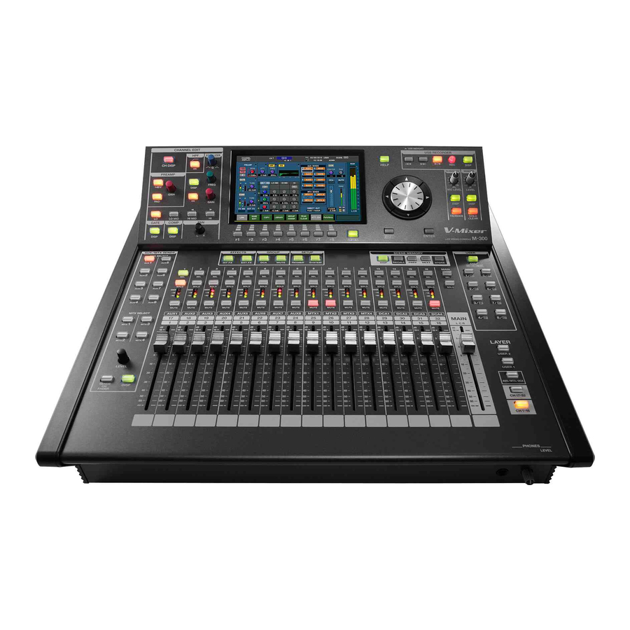
Explanation of the panels Top panel/Front panel fig.TopPanelGuide.eps 14 15 Fader module section p. 21 Layer section p. 21 Main fader module p. 22 CHANNEL EDIT section p. 22 Display p. 25 Function button section p. 25 Screen controller section p. -
Page 21: Fader Module Section
Explanation of the panels Fader module section LAYER section fig.FaderModSectGuide.eps fig.LayerSectGuide.eps This section lets you select the channel layer that will be assigned to the fader module section. The button of the currently assigned channel layer will be lit. USER1 layer button USER2 layer button This assigns the user fader layer 1 or user fader layer 2 to the fader module section. -
Page 22: Main Fader Module
Explanation of the panels Main fader module CHANNEL EDIT section fig.MainFaderModGuide.eps fig.ChEditSectGuide.eps SEL button This button selects the MAIN channel so that it can be controlled from the CHANNEL EDIT section or in the screen. It will light if the MAIN channel is selected. By repeatedly pressing [SEL] you can alternately select the MAIN L, MAIN R, or MAIN C channels. - Page 23 Explanation of the panels PREAMP area EQUALIZER area fig.ChEdtPreamp.eps fig.ChEdtEQ.eps • GAIN knob This adjusts the preamp gain of CH1–32. When ATT Ctrl (p. 48) at the CHANNEL DISPLAY screen is on, this always adjusts the attenuator. This adjusts the attenuator of AUX1–8, MTX1–4, or MAIN L/R/ In this area you can operate the 4-band EQ or 8-band EQ that is...
- Page 24 Explanation of the panels GATE area AUX/MTX SENDS area fig.ChEdtGate.eps fig.ChEdtAux.eps In this area you can operate the gate/expander that is provided for CH1–32. • DISP button This accesses the GATE/EXPANDER popup where you can make detailed settings. The button will light red while the popup is shown.
-
Page 25: Display
Explanation of the panels • You can hold down [SHIFT] to modify the range by which a Display value will change when you operate the CHANNEL EDIT section’s knob or the value dial, allowing you to adjust the fig.DisplayGuide.eps setting in finer detail. You can use the user preference SHIFT LOCK (p. -
Page 26: Group Section
Explanation of the panels GROUP section USB MEMORY RECORDER section fig.RecorderSectGuide.eps fig.GroupSectGuide.eps DCA button button This button accesses the DCA GROUP screen where you can Here you can select the song to play, and rewind or fast- control the DCA groups and make settings for them. It will forward the playback. -
Page 27: Talkback/Osc Section
Explanation of the panels TALKBACK/OSC (talkback/oscillator) section USER section fig.TalkbackOscSectGuide.eps fig.UserSectGuide.eps MIC LEVEL knob This adjusts the preamp gain of the talkback mic input over a range of -10dBu–65dBu. DISP button In the TALKBACK/OSCILLATOR screen, you can select a talkback This button accesses the USER screen where you can change mic input from the CONSOLE INPUT 1–4. -
Page 28: Rear Panel
Explanation of the panels Rear panel fig.RearPanelGuide.eps CONSOLE INPUT jacks p. 29 CONSOLE OUTPUT jacks p. 29 REAC A, B ports p. 30 USB connector p. 30 MIDI connectors p. 30 RS-232C/MIDI select switch p. 30 RS-232C connector p. 30 DIGITAL OUT jack p. -
Page 29: Console Input Jacks
Explanation of the panels CONSOLE INPUT jacks CONSOLE OUTPUT jacks fig.ConsInJackGuide.eps fig.ConsOutJackGuide.eps CONSOLE INPUT 1–4 CONSOLE OUTPUT 1–4 These are balanced XLR-3-31 female input jacks for inputting These are balanced XLR-3-32 male output jacks for analog audio signals from microphones or line level outputting analog audio signals. -
Page 30: Usb Connector
Explanation of the panels REAC A, B ports USB connector fig.REACPortGuide.eps fig.USBPortGuide.eps This USB connector can be connected to your PC to control the These are RJ45 connectors for connecting input/output units M-300 remotely. such as the S-1608, S-0816, or S-4000S via Cat5e Ethernet cables. For details, refer to “USB MIDI”... -
Page 31: Power Switch
If you are unsure of the connection method, contact the nearest Roland Service Center, or an authorized Roland distributor, as listed on the “Information” page. -
Page 32: Basic Operation
Basic operation Basic panel operations Selecting the channel layer Operations in the CHANNEL EDIT section fig.LayerBtn.eps Here’s how to edit the channel parameters. In the fader module section or main fader module, press a [SEL] button to select the channel that you want to control. -
Page 33: Home Screen
Basic operation Accessing a screen When you press a screen select button that’s lit in green, or a screen select button that has a blue border, the corresponding screen or popup will appear, and the button will light in red. The following illustration shows the name of the screen or popup that appears for each button: fig.DispBtnGuide.eps EXTERNAL... -
Page 34: Screen Operations
Basic operation Screen operations About the screen display fig.ScrGuide.eps Top display area Main display area fig.ScrTBScrDisp.eps fig.ScrMainArea.eps This area is always shown in the upper part of the screen. Screen name This shows the name of the screen currently shown in the main display area. - Page 35 Basic operation Sub-display area Popup Indication This area shows supplementary information. The following These are popups that are shown overlaid on the main display information is shown: area. They provide a cursor and function buttons for performing operations in the screen. ●...
-
Page 36: Fader Operations
Basic operation Button operations Knob operations fig.Cursor.eps Buttons in the screen are used to turn a function on/off, to execute a command, or to access a screen. To operate a button, move the cursor to the desired button and press [ENTER]. ●... -
Page 37: Editing A Name
Basic operation Editing a name Library operations You’ll use the NAME EDIT popup to edit names. Library operations are performed in the following popups: Here we’ll explain operations that are common to the NAME EDIT CHANNEL LIBRARY popup P.52 popup. AUX/MTX/MAIN LIBRARY popup P.65 GATE/EXP LIBRARY popup... - Page 38 Basic operation Storing data to a library Recalling data from a library Access the desired LIBRARY popup. Access the desired LIBRARY popup. fig.ScrChLib.eps fig.ScrChLib.eps Verify that the desired channel or effect is shown as the Make sure that the applicable channel/effect indication object of the store operation.
-
Page 39: Message Operations
Basic operation Editing the name of library data Message operations You can assign a name of up to twelve characters to user data. ● Use the NAME EDIT popup to edit the name. CONFIRMATION message fig.Confirm.eps Access the desired LIBRARY popup. fig.ScrChLib.eps This message asks you to confirm an operation. -
Page 40: Input Channel Operations
Input channel operations About the input channels The input channels process the audio signals from the input jacks and internal ports, and send them to the MAIN bus and AUX/MTX buses. fig.InBlkDia.eps INPUT MAIN SOLO PATCHBAY C 1 2 3 4 5 6 7 8 1 2 3 4 CH 1–32 PREAMP... -
Page 41: Operations Using The Channel Edit Section
Input channel operations Operations using the CHANNEL EDIT section Most input channel operations can be performed in the CHANNEL EDIT section. Here we will explain input channel operations using the CHANNEL EDIT section. fig.ChEditSection.eps Selecting the channel to edit Viewing the parameter values In the fader module section, press a [SEL] button to select In the CHANNEL EDIT section, press [CH DISP]. -
Page 42: Compressor Operations
Input channel operations Preamp gain adjustments (High-pass filter) operations Use the PREAMP area of the CHANNEL EDIT section to adjust the Use the area of the CHANNEL EDIT section to operate the preamp gain. filter. fig.ChEdtPreamp.eps fig.ChEdtFilter.eps Press [ON] to turn the on/off. -
Page 43: Band Eq Operations
Input channel operations 4-band EQ operations Sending to the AUX/MTX buses Use the EQUALIZER area of the CHANNEL EDIT section to operate Use the AUX/MTX SENDS area of the CHANNEL EDIT section to the EQ. perform these operations. fig.ChEdtEQ.eps fig.ChEdtAux.eps Press [ON] to turn the 4-band EQ on/off. -
Page 44: Operations In The Channel Display Screen
Input channel operations Operations in the CHANNEL DISPLAY screen The principal parameters of an input channel can be operated in the CHANNEL DISPLAY screen. CHANNEL DISPLAY screen fig.ScrChDispGuide.epsz The principal operations for an input channel can be performed in the CHANNEL DISPLAY screen. PAD button Preamp This turns the pad on/off. - Page 45 Input channel operations Gate/expander For the following channels, the preamp area will show only fig.ScrChGate.eps the Ø (phase) button: • Channels to which no input port is patched • Channels to which a port that has no preamp (such as an internal port) is patched ATT (Attenuator) fig.ScrChATT.eps...
- Page 46 Input channel operations 4-band EQ graph Insert indication fig.ScrChIns.eps This shows the approximate response of the 4-band EQ. OL (Overload) indicator This will light red when the output of the 4-band EQ exceeds the OVER Lev setting specified in the METER SETUP popup (p.
- Page 47 Input channel operations AUX/MTX SENDS fig.ScrChSends.eps fig.ScrChPan.eps LCR button This button specifies how signals are sent from the channel to MAIN L/R and MAIN C. Explanation button The signals sent to MAIN L/R and MAIN C can be individually turned on/off by using the LR button and C Here you can adjust the sends from the channel to the button.
- Page 48 Input channel operations The function buttons have the following operations: Group fig.ScrChGroup.eps [F1 (LINK)] Turns channel link on/off (p. 49). [F2 (NAME EDIT)] Accesses the NAME EDIT popup, where you can specify the channel name (p. 50). [F3 (COPY)] Accesses the CH COPY popup, where you can This indicates whether the channel is assigned to a DCA group or copy channel settings (p.
-
Page 49: Stereo-Linking Channels
Input channel operations Accessing the CHANNEL DISPLAY screen Stereo-linking channels In the fader module section, press [SEL] to select a Adjacent odd-numbered and even-numbered channels can be channel. stereo-linked so that their parameters will have the same settings. This is convenient when you’re dealing with stereo In the CHANNEL EDIT section, press [CH DISP] to access sources. -
Page 50: Specifying A Channel Name And Color Label
Input channel operations The function buttons have the following operations: Specifying a channel name and [F1 (Recall Enters the name selected in the TEMPLATE list color label Template)] into the name edit field. [F2 (HISTORY)] Successively recalls the channel names that You can specify a channel name and color label for each input have been entered since power-up, starting channel. -
Page 51: Copying Channel Settings To Another Channel
Input channel operations Press [F3 (COPY)] to access the CHANNEL COPY popup. Using the template to enter a channel fig.ScrChCopyGuide.eps name Access the NAME EDIT popup for the desired channel. fig.ScrChNameEdit.eps Copy-source channel Move the cursor to the CATEGORY list in the TEMPLATE This indicates the copy-source channel. -
Page 52: Using The Channel Library
Input channel operations Press [F3 (PASTE)]. Recall parameter select buttons COPYCHConf1.eps Use these to select the parameters that will be recalled. You can select the following parameters: Phase Phase Attenuator HPF (high-pass filter) A confirmation message will appear, asking you to confirm Gate Gate/expander the Copy operation. -
Page 53: Assigning Channels To Dca Groups And Mute Groups
Input channel operations Assigning channels to DCA Assigning a channel to a DCA group groups and MUTE groups Access the GROUP ASSIGN popup for the desired channel. fig.ScrChGroupAssign.eps Input channels can be assigned to DCA groups and mute groups. Assignments to DCA groups and mute groups are made in the GROUP ASSIGN popup. -
Page 54: Aux, Mtx, Main Operations
AUX, MTX, MAIN operations About AUX, MTX, MAIN The AUX and MAIN process the mixed audio signals from the input channels, and send them to the output ports. MTX (MATRIX) process a mix of the audio signals from input channels, AUX1–8, and MAIN, and send them to an output ports. fig.OutBlkDia.eps MAIN SOLO... -
Page 55: Operations Using The Channel Edit Section
AUX, MTX, MAIN operations Operations using the CHANNEL EDIT section Most operations for the AUX, MTX, and MAIN can be performed in the CHANNEL EDIT section. Here we will explain channel operations using the CHANNEL EDIT section. fig.ChEditSection.eps Selecting the channel to edit Viewing the parameter values Press [AUX/MTX/DCA] layer button. - Page 56 AUX, MTX, MAIN operations ATT (Attenuator) adjustments 8-band EQ operations Use the PREAMP area of the CHANNEL EDIT section to adjust the Use the EQUALIZER area of the CHANNEL EDIT section to operate attenuator. the EQ. fig.ChEdtEQ.eps Use the GAIN dial to adjust the attenuator. fig.ChEdtPreamp.eps Limiter operations This operation is performed in the COMP area of the CHANNEL...
- Page 57 AUX, MTX, MAIN operations Operating on MTX Sending to the MTX buses Press [SEL] of the MTX to select the send-destination MTX This operation is performed in the AUX/MTX SENDS area of the bus. CHANNEL EDIT section. Press [AUX1]–[AUX8] on the AUX/MTX SENDS area to You can adjust the send level in either of two ways: operating on select the send-source AUX.
-
Page 58: Operations In The Channel Display Screen
AUX, MTX, MAIN operations Operations in the CHANNEL DISPLAY screen The principal parameters of the AUX, MTX, and MAIN can be operated in the CHANNEL DISPLAY screen. CHANNEL DISPLAY screen fig.ScrChMainGuide.eps ATT (Attenuator) Limiter fig.ScrMtxAttGuide.eps fig.ScrChLim.eps OL (Overload) indicator LIM button This will light red when the output of the attenuator exceeds This turns the limiter on/off. - Page 59 AUX, MTX, MAIN operations EQ button For details, refer to “Limiter operations” (p. 78). This turns the 8-band EQ on/off. Insert indication OL (Overload) indicator fig.ScrChInsOut.eps This will light when the output of the 8-band EQ exceeds the OVER Lev setting specified in the METER SETUP popup (p. 96).
- Page 60 AUX, MTX, MAIN operations MTX SENDS (AUX, MAIN only) TO MAIN (AUX only) fig.ScrMtxSends.eps fig.ScrChMainSend.eps Here you can adjust the sends from the AUX1–8 or MAIN L/ R/C to the MTX1–4. These specify the amount of signal that will be sent from the AUX to MAIN.
- Page 61 AUX, MTX, MAIN operations Balance fig.ScrChBal.eps • When LCR button is off This adjusts the left/right panning of the audio signal sent to the MAIN L/R buses in a range of L63–R63. • When LCR button is on This adjusts the left/center/right panning of the audio signal sent to the MAIN L/R/C buses in a range of L63–R63.
- Page 62 AUX, MTX, MAIN operations The function button specific to the MAIN C has the following DELAY operation: fig.ScrChDelay.eps [F1 (LINK to MAIN L/R)] If you turn this on, you’ll be able to use the MAIN fader to control MAIN L/R and MAIN C while maintaining the fader balance between MAIN L/R and MAIN C 64).
-
Page 63: Stereo-Linking Aux/Mtx
AUX, MTX, MAIN operations Press [F1 (LINK)]. Accessing the CHANNEL DISPLAY screen fig.ScrAuxLinkConf.eps In the fader module section, press [SEL] to select channel. Each time you press the MAIN [SEL], it will select the MAIN L, MAIN R, or MAIN C one after another. A confirmation message will appear, asking you to confirm In the CHANNEL EDIT section, press [CH DISP] to access the stereo-link operation. -
Page 64: Linking Main L/R And Main C
AUX, MTX, MAIN operations Linking MAIN L/R and MAIN C Copying channel settings to another channel If you turn [F1 (LINK to MAIN L/R)] on, you’ll be able to use the MAIN fader to control MAIN L/R and MAIN C simultaneously, Channel settings can be copied to another channel. -
Page 65: Using The Aux/Mtx/Main Library
AUX, MTX, MAIN operations The function buttons have the following operations: Using the AUX/MTX/MAIN library [F3 (PASTE)] Executes the copy. You can recall channel settings from the library, or store the [F8 (CLOSE)] Closes the popup. settings of the current channel in the library. Move the cursor to the desired copy parameter select AUX/MTX/MAIN library operations are performed in the AUX/ button, and press [ENTER] to select it. -
Page 66: Assigning Channels To Dca Groups And Mute Groups
AUX, MTX, MAIN operations Copying the MAIN mix Noise may occur when you preview or recall a library item, (AUX1–8 only) but this is not a malfunction. Access the CHANNEL DISPLAY screen for the AUX to The function buttons have the following operations: which you want to copy the MAIN mix. -
Page 67: Copying A Mtx Mix To Another Mtx (Mtx1-4)
AUX, MTX, MAIN operations Copying a MTX mix to another MTX (MTX1–4) You can copy the mix from one MTX to another MTX. Use the COPY MTX MIX popup to perform this operation. Access the CHANNEL DISPLAY screen for the desired copy-source MTX. -
Page 68: Dynamics
Dynamics Gate/expander operations A gate/expander is provided on CH1–32, and can be used as a gate, an expander, or a ducking processor. A gate applies a user-adjustable level of attenuation (RANGE) to input signals that are lower than the threshold level. ffig.GateCurve.eps INPUT SIGNAL OUTPUT SIGNAL... - Page 69 Dynamics Gate GATE/EXPANDER popup fig.PopGateGuide2.eps fig.PopGateGuide.eps THRESH knob This adjusts the threshold level in a range of -80.0 dB–0.0 dB. RANGE knob This adjusts the RANGE in a range of -Inf dB–0.0 dB. KEY-IN meter ATTACK knob This indicates the level of the key-in signal. For stereo-linked channels, two meters are shown (L and R).
- Page 70 Dynamics Expander Ducking fig.PopExpGuide.eps fig.PopDuckGuide.eps THRESH knob THRESH knob This adjusts the threshold level in a range of -80.0 dB–0.0 dB. This adjusts the threshold level in a range of -80.0 dB–0.0 dB. RATIO knob RANGE knob This adjusts the RATIO in a range of 1.00:1–INF:1 (14 steps). This adjusts the RANGE in a range of -Inf dB–0.0 dB.
- Page 71 Dynamics KEY-IN SELECT popup button Accessing the GATE/EXPANDER popup This accesses the KEY-IN SELECT popup where you can select In the fader module section, press a [SEL] button to select the key-in signal. For stereo-linked channels, there will be the desired channel. two (L and R).
- Page 72 Dynamics [F5 (CONSOLE)] Displays CONSOLE IN1–12as the key-in signal Selecting the key-in signal for the gate/ select buttons. expander [F6 (SELECT SELF)] Selects the channel itself as its own key-in signal. The key-in signal used by the gate/expander is taken from the [F8 (CLOSE)] Closes the popup.
- Page 73 Dynamics function buttons have the following operations: Listing the GATE/EXPANDER states [F8 (CLOSE)] Closes the popup. Access the GATE EXPANDER popup. fig.PopGate.eps Using the gate/expander library You can recall gate/expander settings from the library, or store the current gate/expander settings in the library. The GATE/EXP LIBRARY popup is used to perform gate/expander library operations.
-
Page 74: Compressor Operations
Dynamics Compressor operations Compressors are provided on CH1–32. They apply a user-adjustable ratio of attenuation to input signals that exceed the threshold level. fig.CompCurve.eps INPUT SIGNAL (KNEE=HARD, GAIN=0.0dB, AUTO GAIN=OFF) (RATIO=INF:1) OUTPUT SIGNAL THRESHOLD ATTACK RELEASE RATIO THRESHOLD INPUT LEVEL TIME The COMPRESSOR popup is used to perform compressor operations. - Page 75 Dynamics GAIN knob FREQ knob This adjusts the GAIN in a range of -40.0 dB–+40.0 dB. This This adjusts the frequency in a range of 20 Hz–20.0 kHz. adjusts the output level of the compressor. The function buttons have the following operations: If AUTO GAIN is on, the GAIN will have an effective range of -40.0 [F1 (OVERVIEW) Accesses the COMPRESSOR OVERVIEW popup...
- Page 76 Dynamics [F6 (SELECT SELF)] Selects the channel itself as its own key-in Selecting the key-in signal for the signal. compressor [F8 (CLOSE)] Closes the popup. The key-in signal used by the compressor is taken from the post- Move the cursor to the desired key-in signal select gate point of the channel itself or any of the following sources: button, and press [ENTER] to select it.
- Page 77 Dynamics The function buttons have the following operations: Listing the COMPRESSOR states [F8 (CLOSE)] Closes the popup. Access the COMPRESSOR popup. fig.PopComp.eps Using the compressor library You can recall compressor settings from the library, or store the current compressor settings in the library. The COMP LIBRARY popup is used to perform compressor library operations.
-
Page 78: Limiter Operations
Dynamics Limiter operations Limiters are provided on each AUX1–8, MTX1–4, and MAIN L/R/C. They attenuate the signal so that the output does not exceed the threshold level. fig.LimCurve.eps INPUT SIGNAL (KNEE=HARD) OUTPUT SIGNAL THRESHOLD ATTACK RELEASE THRESHOLD INPUT LEVEL TIME The LIMITER popup is used to perform limiter operations. - Page 79 Dynamics Parameters Using the limiter library In this field you can edit the compressor parameters. You can recall limiter settings from the library, or store the fig.PopLmtGuide2.eps current limiter settings in the library. The LIMITER LIBRARY popup is used to perform limiter library operations.
-
Page 80: 4-Band Eq/8-Band Eq
4-band EQ/8-band EQ 4-band EQ operations (CH1–32) 4-band EQ is provided on each input channel. The LO and HI bands provide shelving-type or peaking-type filters, and the LO-MID and HI-MID bands provide peaking-type filters. fig.EQCurve.eps LO-MID HI-MID GAIN GAIN FREQUENCY FREQ FREQ FREQ... - Page 81 4-band EQ/8-band EQ GAIN knob Using the 4-band EQ library This adjusts the gain of each band in a range of -15.0 dB– You can recall 4-band EQ and HPF settings from the library, or +15.0 dB. store the current 4-band EQ and HPF settings to the library. The 4-BAND EQ LIBRARY popup is used to perform 4-band EQ Noise may occur when you operate the HPF or 4-band EQ, library operations.
-
Page 82: 8-Band Eq Operations (Aux/Mtx/Main)
4-band EQ/8-band EQ 8-band EQ operations (AUX/MTX/MAIN) 8-band EQ is provided on AUX1–8, MTX1–4, and MAIN L/R/C. Band 8 type You can select one of the three filter types on band 1 and band 8. You can select one of the following filter types: Band 2–7 provide peaking-type filters. - Page 83 4-band EQ/8-band EQ Press [F4 (LIBRARY)] to access the 8-BAND EQ LIBRARY Setting the 8-band EQ to a flat state popup. fig.Pop_8BandEQLibGuide.eps Access the 8-BAND EQ popup. fig.Pop_8BandEQ.eps Channel indication This indicates the channel to which the 8-BAND EQ LIBRARY Press [F6 (FLAT)].
-
Page 84: Aux Send/Mtx Send
AUX send/MTX send AUX/MTX send operations (CH1–32) The AUX/MTX sends are used to send audio signals from input channels to AUX1–8 and MTX1–4. fig.InBlkSends.eps CH 1-32 MAIN SOLO C 1 2 3 4 5 6 7 8 1 2 3 4 PRE EQ PRE FADER POST FADER... - Page 85 AUX send/MTX send fig.PopAuxSendField2Guide.eps Setting all AUX/MTX send points in a singe operations Press the [SEL] button of any channel CH1–32 to select an input channel. Pan slider In the CHANNEL EDIT section’s AUX/MTX SENDS area, This adjusts the left/right panning of the signal sent to the press [DISP] to access the AUX/MTX SENDS popup.
-
Page 86: Mtx Send Operations
AUX send/MTX send MTX send operations The MTX sends are used to send audio signals from AUX1–8 or MAIN L/R/C to MTX1–4. fig.OutBlkMtxSends.eps MAIN L, R, C POST ATT PRE EQ PRE FADER POST FADER OUTPUT POST DELAY EXT FX TO MONITOR SEL FADER BAL MUTE... - Page 87 AUX send/MTX send If MTX is stereo-linked, the following parameters will be shown for the odd-numbered MTX send: fig.PopMtxSendField2Guide.eps Pan slider This adjusts the left/right panning of the signal send to the stereo-linked MTX in a range of L63–R63. The function buttons have the following operations: [F3 (ALL ON) Turns on all send switches for each send field.
-
Page 88: Input/Output Patchbay
Input/output patchbay Default setting of the input/output patchbay Default settings of the input patchbay When the M-300 is in its default state, the input patch bay is set as follows: Input channel Input port CH1–16 REAC A IN1–16 CH17–28 CONSOLE IN1–12 CH29–30 FX4 OUT L, R CH31–32... -
Page 89: Patchbay Operations
Input/output patchbay Patchbay operations You can change the settings of the input/output patchbays. Use Jack indication the PATCHBAY screen to perform patchbay operations. This indicates the jack number. For the input patchbay, this also indicates the signal level at the input jack. Accessing the PATCHBAY screen The color indicates the signal level as follows: In the... -
Page 90: Input Patchbay Operations
Input/output patchbay Input patchbay operations Editing the input patching If you attempt to patch a CONSOLE IN that an EXT FX is Access the PATCHBAY screen. using, a caution message such as the following will appear: fig.ScrPatchIn1608.eps fig.ScrInPatchExtFx.eps Press [F8 (DISABLE)] to disable the corresponding EXT FX and continue with the patching change. - Page 91 Input/output patchbay Level meter Editing the preamp This indicates the input level. You can setup the preamp gain of the input jacks directly. +48V buttons This turns the +48V phantom power on/off. It is useful when an input jack is not patched to M-300’s input channel, but is a split source used for a multi-channel recording system.
-
Page 92: Output Patchbay Operations
Input/output patchbay Output patchbay operations Editing the output patching If you attempt to patch to a CONSOLE OUT that an EXT FX is Access the PATCHBAY screen. using, a caution message such as the following will appear: fig.ScrPatchIn1608.eps fig.ScrOutPatchExtFx.eps Press [F8 (DISABLE)] to disable the corresponding EXT FX and continue with the patching change. - Page 93 Input/output patchbay The function buttons have the following operations: [F3 (NAME EDIT)] Accesses the NAME EDIT popup. [F4 (RECALL)] Recalls the selected library data. [F5 (STORE)] Stores the current settings into the selected library data. [F6 (CLEAR)] Clears the selected library data. [F7 (LOCK)] Locks/unlocks the selected library data.
-
Page 94: Metering
Metering AUX/MTX/MAIN meter point About the meters This indicates the point at which the AUX/MTX/MAIN meters are detecting the level. Here we will explain the METER screen, which shows the levels of the channels. AUX/MTX/MAIN meters Accessing the METER screen These indicate the level and fader position for AUX1–8, MTX1–4, and MAIN L/C/R. -
Page 95: Viewing The Channel Strip Of The Channel Layer
Metering Viewing the channel strip of the channel layer You can view the channel strip of all of the input channels or Channel number/name output channels in the current layer of the top panel. This indicates the channel number and name. To view the channel strips, use the LAYER VIEW tab of the METER screen. -
Page 96: Editing The Meter Settings
Metering Editing the meter settings In the METER SETUP popup you can change the level detection button is on. point of the meter, and make peak hold settings. If CONTINUE is selected, the indication will remain until you Accessing the METER SETUP popup execute the PEAK CLEAR operation (by pressing a function button) in the METER screen, etc. -
Page 97: Listing The Channel Names And Group Names
Metering Listing the channel names and group names NAME LIST tab fig.ScrMeterList_Guide.eps Name list This lists the names of each channel and group. fig.List_Compo_Guide.eps Name This is the name of the channel or group. If you move the cursor to the name of a channel, that channel will become the selected channel. -
Page 98: Effects
Effects About effects fig.EffectDia.eps INPUT OUTPUT SELECT SELECT CH 1 FX INSERT OUT INPUT OUTPUT To CH 1 FX INSERT IN CH 32 FX INSERT OUT To CH 32 FX INSERT IN FX 1 AUX 1 FX INSERT OUT To AUX 1 FX INSERT IN EFFECT AUX 8 FX INSERT OUT To AUX 8 FX INSERT IN... -
Page 99: Accessing The Effects Screen
Effects ● Dual mono Accessing the EFFECTS screen fig.ScrFxTypeMM.eps In the EFFECTS section, press [INT FX]. fig.ScrFxRack.eps This allows the effect to be used as two monaural effects. These effects are used mainly for insertion in a channel. ● Singe mono fig.ScrFXTypeSingleMono.eps This is a singe monaural type effect. -
Page 100: Effect Input/Output Settings
Effects Effect input/output settings The FX INSERT/SOURCE SELECT popup and the FX DESTINATION The function buttons have the following operations: SELECT popup are used to select the input-source and output- [F1 (CH 1–32 INSERT)] Displays CH1–32 as the insert-destination destination for the effect. channel select buttons. - Page 101 Effects Specifying the effect return channel Current output-destination indication Access the EFFECTS screen. This indicates the current output-destination channel. Move the cursor to the FX DESTINATION SELECT popup button L for FX3, and press [ENTER]. If more than one output-destination channel are exist, the fig.ScrFXOutSel2.eps lowest number channel is shown.
-
Page 102: Editing Effect Parameters
Effects Editing effect parameters The FX EDIT popup is used to edit the effect parameters. Editing effect parameters Accessing the FX EDIT popup Access the FX EDIT popup for the desired effect. fig.ScrFxEdit.eps Access the EFFECTS screen. fig.ScrFxRack.eps Use [F1]–[F6] to switch between tabs to view the parameters you want to edit. -
Page 103: Setting The Tempo
Effects Applicable effect indicator Setting the tempo This indicates the FX to which the FX LIBRARY popup applies. From the FX EDIT popup for delay-type effects, you can access the TEMPO popup, which lets you set the tempo used for delay- RAM Access field type effects. -
Page 104: Using The 31-Band Geq
Effects Using the 31-band GEQ Recalling “GEQ x1” on the FX LIBRARY popup allows you to use Insert into MAIN R the FX as a 31-band GEQ. Move the cursor to the FX INSERT/SOURCE SELECT popup Recalling the 31-band GEQ button L for FX2, and press [ENTER]. - Page 105 Effects fig.ScrFXEdit_GEQ_Guide.eps While using the top panel faders to control the 31-band GEQ, [MUTE] buttons will blink for the faders the position of which is anything other than 0.0dB. When you press the blinking [MUTE], the fader will be reset to the 0.0dB position. GEQ faders For each frequency band, these adjust the amount of boost or cut in a range of -15.0dB–...
-
Page 106: Inserting An External Effects Device
Inserting an external effects device About inserting an external effects device fig.ExtInsDia.eps INSERT INSERT CONSOLE INPUT 5-8 CH 1 EXT FX INSERT OUT To CH 1 EXT FX INSERT IN CH 32 EXT FX INSERT OUT To CH 32 EXT FX INSERT IN SEND RETURN AUX 1 EXT FX INSERT OUT... -
Page 107: Inserting An External Effects Device Into A Channel
Inserting an external effects device Inserting an external effects device into a channel To insert an external effects device into a channel, connect the [F2 (BUS INSERT)] Displays AUX1–8, MTX1–4, and MAIN L/R/C CONSOLE IN jack and CONSOLE OUT jack to your external effects the insert-destination channel select buttons. -
Page 108: Dca Groups
DCA groups The function buttons have the following operations: About DCA groups [F6 (DCA If this is on, the top panel fader modules 13–16 ON FADER) will control DCA groups. DCA grouping is a function that lets you make relative adjustments to the output level of channels so that the level of [F7 (NAME EDIT)] Accesses the NAME EDIT popup (p. -
Page 109: Specifying A Name And Color Label For The Dca Group
DCA groups Assigning a channel to a DCA group Using the panel to control DCA groups Access the DCA GROUP ASSIGN popup for the desired DCA group. fig.ScrDCAGroupAssign.eps You can use the AUX/MTX/DCA layer of the fader module section to control DCA groups from the panel. In the layer section, press [AUX/MTX/DCA] to access the... -
Page 110: Mute Groups
Mute groups About mute groups Assigning a channel to a mute group Mute grouping is a function that lets you control the mute status of multiple channels belonging to a mute group. A channel can The MUTE GROUP ASSIGN popup is used to assign a channel to a belong to more than one mute group. -
Page 111: Specifying A Name And Color Label For A Mute Group
Mute groups Move the cursor to the desired channel select button, Move the cursor to the MUTE group button of the desired and press [ENTER] to select it. mute group, and press [F7 (NAME EDIT)]. fig.ScrChNameEdit.eps Press [F8 (CLOSE)] to close the popup. When the MUTE GROUP ASSIGN popup is displayed, you can press a top panel [SEL] to turn on/off the corresponding channel’s assignment to the mute group. -
Page 112: Talkback/Oscillator
Talkback/Oscillator About talkback and oscillator fig.TB-OSCFlow.eps MAIN C 1 2 3 4 5 6 7 8 1 2 3 4 TALKBACK / OSCILLATOR TALKBACK / OSC OUT TALKBACK / OSC OSC ON SELECT CONSOLE INPUT 1 TALKBACK LEVEL CONSOLE INPUT 2 OSC ON CONSOLE INPUT 3 CONSOLE INPUT 4... -
Page 113: Using Talkback
Talkback/Oscillator The function buttons have the following operations: MIC SELECT buttons These select the CONSOLE IN that connects a talkback mic. (OSC ON)] Turns the oscillator on/off. Using talkback The preamp gain of the selected CONSOLE IN will be locked by the MIC LEVEL knob on the TALKBACK/OSC section. -
Page 114: Monitor/Solo
Monitor/Solo About monitoring fig.MonitorFlow.eps SOLO MONITOR OUTPUT PATCHBAY MONITOR MONITOR SELECT SOLO MONITOR AUX 1 OUT LOGIC LEVEL AUX 8 OUT MONITOR OUT L DELAY MAIN OUT LR MONITOR OUT R MAIN OUT C DELAY MAIN OUT LCR MONO OUT MTX 1 OUT MTX 4 OUT REC OUT LR... -
Page 115: Using Monitor
Monitor/Solo SOLO MODE select buttons [F8 (M-48 MANAGER)] This accesses the M-48 MANAGER popup (p. 170) These select the solo mode from the following choices: ADD ON Channels whose [SOLO] are on will be mixed for monitoring. Using Monitor LAST Only the channel whose [SOLO] was turned on most recently will be monitored. -
Page 116: Scene Memory
Scene memory About scene memory About the scene indication in the top display area Scene memory is a function that lets you store mixer parameters fig.ScrTBSceneDispGuide.eps as a scene, and recall them when desired. Scene memory is a function that lets you store and recall mixing parameters as “scenes.”... - Page 117 Scene memory SCENE MEMORY section If the “SCENE/LIB STORE” button located in the CONFIRMATION fig.SceneMemSectGuide.eps area of User Preferences (p. 137) is not selected, no confirmation message will appear in step 5. If “LOCK” is indicated next to the scene number, that scene is locked, and you can’t store to it.
-
Page 118: Operations In The Scene Screen
Scene memory The function buttons have the following operations: Operations in the SCENE screen [F1 (RECALL)] This recalls the mixer parameters from the currently selected scene number. The SCENE screen is used to edit the scene list and make various scene settings. -
Page 119: Editing The Scene List
Scene memory Memory number Editing the scene list This specifies the M-48 memory number that will be recalled for all connected M-48 units. The SCENE LIST EDIT popup is used to edit the scene list. RECALL PARAMETERS select buttons Accessing the SCENE LIST EDIT popup These buttons specify the parameters that will be recalled if the recall filter is turned on. -
Page 120: Cutting A Scene
Scene memory ●INSERT Editing the name of a scene If you press [F5 (INSERT)], a message will ask you to confirm the Insert operation. You can assign a name of up to sixteen characters to each scene. Access the SCENE LIST EDIT popup. From the scene list, select the scene whose name you want to edit. -
Page 121: The Global Scope Function
Scene memory Parameter recall scope buttons Erasing the contents of a scene (CH1–32, AUX/MTX/MAIN tab) Access the SCENE LIST EDIT popup. These buttons specify the scope of the parameters that will be recalled for the channels selected by the channel recall From the scene list, select the scene whose contents you scope buttons. -
Page 122: Synchronizing Scene Memories With M-48 Memories
Scene memory Use the DCA/MUTE group recall scope buttons of OTHER parameter recall scope buttons (OTHER)] to specify the DCA/MUTE groups that will be Use these to specify other parameters that will be included recalled. in the scope of recall. fig.ScrRecallSafeOther.eps Select the parameters that you want to include in the scope of recall, and de-select the parameters that you don’t want... - Page 123 Scene memory The function buttons have the following operations: By holding down [SHIFT] and pressing [ ] or [ ], you can [F1 ( PREV UNIT)] Change the target unit. quickly move the cursor between the name edit field and M-48 [F2 (NEXT UNIT )] MEMORY.
-
Page 124: Usb Memory Recorder
USB memory recorder About the USB memory recorder About USB memory The M-300 provides a two-track recorder function that uses USB The USB memory used by the USB memory recorder must be memory. This function allows you to choose any two sources able to read or write data with sufficient speed when used from AUX1–8, MTX1–4, MAIN L, MAIN R, MAIN C, MAIN MONO, with the M-300. -
Page 125: Using The Usb Memory Recorder
USB memory recorder Recorder display Using the USB memory recorder fig.ScrRcdrDisp.eps USB memory recorder settings are made in the RECORDER screen. Accessing the RECORDER screen In the USB MEMORY RECORDER section, press [DISP]. fig.ScrRecorderGuide.eps Recorder status This indicates the recording or playback status of the USB memory recorder. - Page 126 USB memory recorder ig.ScrRcdrSrcSelectGuide.eps If more than one output-destination channel are exist, the lowest number channel is shown. The function buttons have the following operations: [F1 ( Selects the previous WAV file. Holding this down during playback rewinds the WAV file being played. [F2 ( Selects the next WAV file.
-
Page 127: Recording To Usb Memory
USB memory recorder fig.ScrRcdrDestSelectGuide.eps Press [ The selected WAV file will play. The sub-display area shows the playback time. fig.SubDispRcdr.eps Pressing and holding [ ] during playback rewinds the playback, and pressing and holding [ ] fast-forwards it. To stop playback, press [ The RECORDER DESTINATION SELECT popup will appear. -
Page 128: User Settings
User settings About user settings Each user who uses the M-300 can have their own individual user settings. These settings can be used according to the level of the Do not disconnect the USB memory or switch off the M-300’s user to restrict the range of channels and parameters that can be power while data is being saved to USB memory. - Page 129 User settings Accessing the USER screen Switching user settings Access the USER screen. In the USER section, press [DISP]. fig.ScrUser.eps fig.ScrUserGuide.eps The USER screen will appear. From the user list, select the desired user. Current user indication Press [F1 (CHANGE USER)]. This shows the current user name.
- Page 130 User settings ENTER PASSWORD popup. Creating user settings fig.ScrUserPwdErr.eps You can create user settings if the current user setting has ADMIN privileges. User settings are created on USB memory. Connect USB memory to the USB memory connector. Access the USER screen. Switching to user settings in USB memory is performed as fig.ScrUser.eps follows:...
- Page 131 User settings Saving the current user settings in USB Deleting user settings memory Here’s how to delete user settings from USB memory. Here’s how to save the current user settings in USB memory. This You can delete user settings if the current user setting has ADMIN can be done if the current user setting is other than ADMIN or privileges.
- Page 132 User settings If the contents entered in the PASSWORD field and the Changing the password of user settings CONFIRM field do not match, the following error message will appear. You can change the password for ADMIN or USER settings. fig.ScrUserPwdMatchErr.eps If you have specified a password, an ENTER PASSWORD popup will appear when you switch user settings.
-
Page 133: Limiting The Range Of Possible Operations
User settings Limiting the range of possible operations You can limit the range of operations that are possible by editing Channel access permission buttons the user levels to correspond to the user settings. These buttons select the channels that the user will be able You edit the user level at the USER LEVEL popup. -
Page 134: Editing The User Fader Layers
User settings Use the ADMIN button to specify whether the user will Editing the user level have ADMIN privileges. The USER LEVEL popup is used to edit the user level. Use [F1 (CH 1–32)] to access the CH 1–32 tab, and specify the channels and parameters to which the user will have access. - Page 135 User settings Use [F1 (CH 1–32)], (AUX/MTX/MAIN)] or (DCA)] to Applicable user indication access the tab that contains the desired channel. This indicates the user settings to which the USER Move the cursor to the desired channel, and press PREFERENCE popup applies. [ENTER] to select it.
-
Page 136: Editing The User Button
User settings Editing the user button The user buttons are a function for assigning desired functions to Move the cursor to the desired user button assignment, the [1] through [8] buttons on the USER section (p. 27). You can and press [ENTER]. make settings for 16 user buttons. -
Page 137: Editing Other User Preferences
User settings Editing other user preferences Access the USER screen. modes: fig.ScrUser.eps Channel SELECT [SOLO] will select the channel. follows SOLO button Channel SELECT The selected channel for each layer is changes with Layer remembered, and button operations in the Selection layer section will change the selected channel. -
Page 138: Reac Applications And Settings
REAC applications and settings REAC applications This chapter explains more advanced ways to use REAC. operate as the REAC master or the REAC slave. For basic information about REAC, refer to “Basic knowledge REAC A port output about REAC” (p. 13). The forty channels from the output patchbay are output to the REAC splitting REAC A port. -
Page 139: Reac Connection Examples
REAC applications and settings REAC connection examples Here we show some examples of REAC setups and connections. Recording to a PC For details on REAC settings for the M-300, refer to “REAC settings” (p. 140). You can use a REAC driver with SONAR DAW software to record from the M-300’s REAC port to a computer. -
Page 140: Reac Settings
REAC applications and settings Monitor/Broadcast console setup REAC settings Set the M-300’s REAC setting to MONITOR/BROADCAST A (p. The SETUP tab of the REAC CONFIG popup is used to make REAC 140). REAC A will be the REAC split, and REAC B will be the REAC settings for the M-300. - Page 141 REAC applications and settings refer to “REAC connection examples” (p. 139). Press [F2 (REAC A)] (or [F3 (REAC B)]) to access the REAC A tab (or the REAC B tab). Use the setup display area to check the input/output unit fig.ScrSysReacConfABGuide.eps connections, REAC mode settings for the input/output units, and the signal flow.
-
Page 142: Editing The S-4000M's Input/Output Settings
REAC applications and settings Editing the S-4000M’s Input/Output Settings The S-4000M has a Merge patchbay and an Output patchbay S-4000M CONFIGURATION popup (Output patchbay supports S-0808 8x8 I/O UNITS only). You can edit the S-4000M’s Merge/Output patchbays using S-4000 RCS to To edit S-4000M’s Merge/Output patchbay, use the S-4000M change input/output assignments. - Page 143 REAC applications and settings Accessing the S-4000M CONFIGURATION Resetting S-4000M Input/Output Setups popup (System Reset) In the SETUP section, press [SYSTEM] to access the You can reset and optimize the merge/output patchbays SYSTEM screen. according to the devices physically connected to REAC ports 1–4. fig.ScrSystem.eps This has the same function as [AUTO MAP SLAVE UNITS] button on S-4000M’s front panel.
-
Page 144: Merge Patchbay Operations
REAC applications and settings Merge Patchbay Operations Access the S-4000M CONFIGURATION popup. REAC channel indication This indicates the number of the REAC channels being sent to the M- Press [F1 (MERGE)] to access the MERGE tab. 300. fig.S4M_Config_IN_Guide.eps Input indication This indicates the input numbers of the REAC slave device and the signal level s. -
Page 145: Output Patchbay Operations (S-0808)
REAC applications and settings Output Patchbay Operations (S-0808) Access the S-4000M CONFIGURATION popup. REAC channel indicator This indicates the number and the signal level of the REAC Press [F2 (OUTPUT)] to access the OUTPUT tab. channels being sent from the M-300. fig.S4M_Config_OUT_Guide.eps The color indicates the signal level as follows: Color... -
Page 146: Splitting Merged Inputs (S-4000M's Split Function)
REAC applications and settings Splitting Merged Inputs (S-4000M's Split Function) By using the S-4000M’s Split Function, you can split the merged Using S-4000M’s split function inputs (being sent to the M-300) to REAC port 4 of the S-4000M. It is very convenient when splitting to a monitor console or a multi- Access the S-4000M CONFIGURATION popup. -
Page 147: Saving/Loading The S-4000M's Input/Output Setups
REAC applications and settings Saving/Loading the S-4000M’s Input/Output Setups You can save/load the S-4000M input and output setups to a USB Saving the S-4000M Input/Output Setup memory as an S-4000M Input/Output Setup file. file To save/load the S-4000M Input/Output Setup File, use the S- 4000M LOAD/SAVE popup. -
Page 148: Remote
M-300 from an external computer or other device. For details on the RS-232C commands, refer to the “M-300 RS-232C Reference” (PDF version), which you can obtain from the Roland website listed below: In order to use V-LINK, the MIDI/RS-232C select switch of the M- 300 must be set to the MIDI position. -
Page 149: Remote Settings
Remote Remote settings The REMOTE popup of the SYSTEM screen is used to make remote settings. Always make sure to switch off the M-300’s power before you change the setting of the MIDI/RS-232C select switch. MIDI settings Dev ID knob The MIDI tab of the REMOTE popup is used to make MIDI settings. - Page 150 Remote minimum (0%), in a range of -Inf dB–+10.0 dB. V-LINK settings Move the cursor to the Dev ID knob and specify the To make V-LINK settings, use the V-LINK tab of the REMOTE device ID. popup. Move the cursor to the V-LINK SOURCE CHANNEL SELECT In the SETUP section, press [SYSTEM] to access the popup button for the desired source, and press [ENTER].
- Page 151 Remote USB MIDI settings RS-232C settings To make USB MIDI settings, use the USB MIDI tab of the REMOTE The RS-232C tab of the REMOTE popup is used to make RS-232C popup. settings. In the SETUP section, press [SYSTEM] to access the In the SETUP section, press [SYSTEM] to access the SYSTEM screen.
-
Page 152: Other Settings And Functions
Other settings and functions System information and basic mixer settings Accessing the SYSTEM screen Viewing system information and making basic mixer settings In the SETUP section, press [SYSTEM]. fig.ScrSystem.eps The SYSTEM screen is used to view system information and make basic mixer settings. - Page 153 Other settings and functions View the system information in the INFORMATION area. Adjusting the brightness of the panel If the Battery indication shows OK, the internal lithium and display battery voltage is satisfactory. If this shows LOW or NG, the voltage is low. Replace the The BRIGHTNESS field of the SYSTEM screen is used to adjust the internal lithium battery as described in “About the internal brightness of the panel, and display.
- Page 154 Other settings and functions When you press [F8 (INIT)], the section you selected in Initializing the mixer settings step 3 will be initialized. If you press [F7 (CANCEL)], the operation will be cancelled. Access the SYSTEM screen. fig.ScrSystem.eps If you attempt to initialize the scenes or libraries when a locked scene or library exists, the following caution message will appear.
-
Page 155: Saving/Loading Mixer Settings
Other settings and functions Saving/loading mixer settings You can use USB memory to save or load mixer settings as a The function buttons have the following operations: project file. The LOAD/SAVE popup of the SYSTEM screen is used [F1 (LOAD)] Loads the project file that is selected in the list to save or load mixer settings. - Page 156 Other settings and functions Saving mixer settings to USB memory Loading mixer settings from USB memory Access the LOAD/SAVE popup. Access the LOAD/SAVE popup. fig.ScrSysLoadSave.eps fig.ScrSysLoadSave.eps Move the cursor to the project file list, and move to the Move the cursor to the project file list, and select the file that you want to load.
- Page 157 Other settings and functions Renaming a project file Deleting a project file Access the LOAD/SAVE popup. Access the LOAD/SAVE popup. fig.ScrSysLoadSave.eps fig.ScrSysLoadSave.eps Move the cursor to the project file list, and select the Move the cursor to the project file list, and select the project file that you want to rename.
-
Page 158: Date&Time Settings
Other settings and functions Date&time settings Use the DATE&TIME popup of the SYSTEM screen to set the date MONTH knob and time. This specifies the month in a range of 1–12. Access the SYSTEM screen. fig.ScrSystem.eps DATE knob This specifies the date in a range of 1–31. The function buttons have the following operations: [F6 (SET)] Finalizes the specified date and time. -
Page 159: Managing Usb Memory
Other settings and functions Managing USB memory The USB MEMORY popup of the SYSTEM SCREEN is used to The function buttons have the following operations: perform USB memory management. [F1 (FORMAT)] Formats the USB memory (p. 159). Accessing the USB MEMORY popup [F2 (MAKE FOLDER)] Creates a folder in the list (p. - Page 160 Other settings and functions Creating a folder Renaming a file or folder name Access the USB MEMORY popup. Access the USB MEMORY popup. fig.ScrSysUSBMem.eps In the file list, move the cursor to the desired file or folder. Press [F3 (NAME EDIT)]. fig.ScrNameEdit.eps The NAME EDIT popup will appear.
-
Page 161: Deleting A File
Other settings and functions Copying a file Deleting a file Access the USB MEMORY popup. Access the USB MEMORY popup. In the file list, move the cursor to the desired file. In the file list, move the cursor to the file you want to delete. -
Page 162: Console Lock
Other settings and functions Console Lock You can lock the console to prevent it from being operated. If a Unlocking the console password has been specified for the current user settings, you will need to enter the password in order to unlock the console. When the console is locked, press [ENTER]. -
Page 163: Help Function
Other settings and functions Help function The Help function explains how to use the M-300. Help shortcuts By holding down [HELP] and pressing a top panel button, you The Help contents are provided only in English. can access the Help content related to that button. Using the Help function You can use the following buttons as Help shortcuts: •... -
Page 164: Other Settings
Other settings and functions Other settings Initializing the M-300’s internal memory Clearing the ADMIN password The following items will be initialized, returning them to the If you’ve forgotten the ADMIN password, you can use the factory settings: following procedure to clear the ADMIN password. •... -
Page 165: Fader Calibration
Other settings and functions [F8 (CLOSE)] Closes the FADER CALIBRATION popup. Fader calibration Add a check mark to the fader select button of the fader If the fader positions are no longer aligned with the index you want to adjust. markings of the top panel, you can use the Fader Calibration function to correct the misalignment. -
Page 166: Management Of The M-48 Live Personal Mixer
Management of the M-48 live personal mixer What is the M-48 live personal mixer? The M-48 is a live personal mixer that allows each musician to The sources 1–40 being input via REAC are mixed by the M-48’s create their own monitor mix. By unifying the professional 40-channel mixer. -
Page 167: Connecting M-48 Units To The M-300
Management of the M-48 live personal mixer LINE OUT Memory functionality As the LINE OUT source, you can choose PHONES (the signal The M-48 has 16 memories, and allows mixer settings to be immediately before PHONES VOLUME), MAIN bus, or AUX stored or recalled. -
Page 168: Editing And Managing M-48 Units
Management of the M-48 live personal mixer Editing and managing M-48 units Each musician will be able to use their M-48 with greater comfort and convenience if the mixing engineer has made the appropriate settings for each M-48. In particular, the mixing engineer should consult with each musician when assigning sources to groups. Each musician can decide what sources they want assigned to which knobs (groups). -
Page 169: Specifying The Outputs From The M-300 To The M-48 Unit
Management of the M-48 live personal mixer Specifying the outputs from the M-300 to the M-48 unit Use the REAC B output patchbay to specify the outputs from the In addition to input channel direct outs, you can use a variety of M-300 to the M-48. -
Page 170: Viewing The Connected M-48 Units
Management of the M-48 live personal mixer Viewing the connected M-48 units You can use the M-48 MANAGER popup to view a list of the M-48 Item Explanation Function of [ENTER] units connected to the M-300's REAC B port. MEMORY If this is checked, Check/uncheck SAFE... - Page 171 Management of the M-48 live personal mixer Editing the M-48’s unit name Changing the order of a unit in the M-48 list Access the M-48 MANAGER popup. A unit name of up to eight characters can be assigned to each M- 48.
-
Page 172: Making Settings For An M-48 Unit
Management of the M-48 live personal mixer Making settings for an M-48 unit Group name Accessing the M-48 SETUP popup This indicates the group name. If you move the cursor here Access the M-48 MANAGER popup. and press [ENTER], the NAME EDIT popup will appear, fig.ScrM48Manager.eps allowing you to edit the group name. - Page 173 Management of the M-48 live personal mixer LINE OUT SOURCE select buttons Making preference settings for an M-48 These buttons select one of the following as the LINE OUT unit source: Access the desired M-48 SETUP popup. Selection Explanation fig.ScrM48Setup.eps MAIN BUS Output the signal of the MAIN BUS.
- Page 174 Management of the M-48 live personal mixer Returning the preference settings to the Assigning group names for an M-48 unit default state Access the desired M-48 SETUP popup. fig.ScrM48Setup.eps Access the desired M-48 SETUP popup. fig.ScrM48Setup.eps In the GROUP MIX (VOLUME) area, move the cursor to the desired group name and press [ENTER].
-
Page 175: Source Level/Pan Settings
Management of the M-48 live personal mixer Source Level/Pan settings fig.ScrM48SrcLev_Guide.eps M-48 SOURCE LEV/PAN popup This popup lets you set the source level and pan. Set the LEVEL, PAN, and AUX switch for each source 1–40. Two views are provided; the SOURCE LAYOUT tab and the M-300 LAYOUT tab. - Page 176 Management of the M-48 live personal mixer Verify that the desired M-48 is shown in the target unit PAN knob indication. This adjusts the source’s panning in a range of L63–C–R63. If the wrong unit is selected, press [F8 (CLOSE)] to close the popup;...
- Page 177 Management of the M-48 live personal mixer values: Press [F8 (OK)]. fig.ScrM48CopyMix_Conf.eps Parameter Value AUX switch LEVEL A message will ask you to confirm the operation. Pressing [F7 (CANCEL)] will cancel the operation and close the popup. In this example, the MAIN L/R mix is being copied. Copying the M-300’s mix levels to the Press [F8 (COPY)];...
-
Page 178: Source Assign Settings
Management of the M-48 live personal mixer Source Assign settings This assigns source 1 through 40 to group 1 through 16 for Source indication operating the M-48 panel. You make assignments to the groups This indicates the number and name of each source. using the M-48 SOURCE ASSIGN popup. -
Page 179: Setting The Source Assignments
Management of the M-48 live personal mixer Setting the source assignments Access the M-48 SOURCE ASSIGN popup. fig.ScrM48SrcAssign.eps In the assignment grid, move the cursor to the location where the desired source and group intersect, and press [ENTER] to make an assignment symbol appear. A source can be assigned only to one group. -
Page 180: Checking And Adjusting The Musician's Mix (Group Mix)
Management of the M-48 live personal mixer Checking and adjusting the musician’s mix (Group Mix) SOLO button Accessing the M-48 GROUP MIX popup This turns solo on/off for each group. Access the desired M-48 SETUP popup. EQ graph fig.ScrM48Setup.eps This indicates the approximate response of the group’s EQ. You can move the cursor here and press [ENTER] to turn the EQ indication on/off. -
Page 181: Checking And Adjusting The Group Mix
Management of the M-48 live personal mixer LO GAIN knob Resetting the group mix to the default This adjusts the LO gain in a range of -15.0 dB – +15.0 dB. settings The function buttons have the following operations: Access the desired M-48 GROUP MIX popup. fig.ScrM48GrpMix1.eps [F1 (LAYER 1-8)] Switches the group layer. -
Page 182: Copying M-48 Settings
Management of the M-48 live personal mixer Copying M-48 settings Access the M-48 MANAGER popup. The function buttons have the following operations: fig.ScrM48Manager.eps [F1 (MARK ALL)] Adds a check mark to all DEST fields of the copy-destination list. [F2 (CLEAR MARKS)] Clears the check marks from all DEST fields of the copy-destination list. -
Page 183: M-48 Memory Operations
Management of the M-48 live personal mixer M-48 memory operations You manipulate M-48 memory using the M-48 MEMORY popup. fig.ScrM48Memory_Guide.eps Accessing the M-48 MEMORY popup Access the M-48 MANAGER popup. fig.ScrM48Manager.eps Target unit indication This indicates the M-48 that is the target of memory operations. - Page 184 Management of the M-48 live personal mixer Storing the M-48’s current memory Recalling a memory to the M-48 Access the M-48 MEMORY popup. Access the M-48 MEMORY popup. fig.ScrM48Memory.eps Select the desired memory in the memory list. If the ALL UNITS tab is shown, all M-48 units will be affected by this operation (except for units whose MEMORY SAFE function is turned on).
-
Page 185: Using The M-48 Library
Management of the M-48 live personal mixer Using the M-48 library The current settings of the M-48 can be organized in the form of a Recall parameter select buttons “Library,” and saved on the M-300. These buttons select the parameters that will be recalled from the library. - Page 186 Management of the M-48 live personal mixer Storing to the M-48 library Recalling settings from the M-48 library Access the M-48 LIBRARY popup. Access the M-48 LIBRARY popup. fig.ScrM48Library.eps In the library list, select the library item that you want to recall.
-
Page 187: Saving/Loading Usb Memory
Management of the M-48 live personal mixer Saving/loading USB memory This loads or stores all data saved in M-48 units as M-48 project The function buttons have the following operations: files on USB memory. [F1 (MARK ALL)] Adds a check mark to all MARK fields of the target unit list. - Page 188 Management of the M-48 live personal mixer Press [F6 (SAVE)]. Loading an M-48 project from USB fig.ScrM48Save.eps memory Access the M-48 LOAD/SAVE popup. fig.ScrM48LoadSave.eps The M-48 SAVE popup will appear. If you selected a single M-48 unit in step 2, specify a file name. If you added a check mark to multiple M-48 units in step 2, specify a folder name.
-
Page 189: Deleting A Project File Or Folder
Management of the M-48 live personal mixer Deleting a project file or folder Access the M-48 LOAD/SAVE popup. In the project file list, select the project file that you want to delete. This operation cannot delete files or folders other than M-48 project files or folders. -
Page 190: Appendix
Appendix User button functions FUNCTION PARAM1 PARAM2 Explanation NONE Unlit SCENE PREV RECALL Lit while held Recalls the scene of the previous number NEXT RECALL Lit while held Recalls the scene of the next number DIRECT RECALL 000–299 Lit while held Recalls the scene of the specified number UNDO RECALL Lit if UNDO is available... -
Page 191: Error Message List
Appendix Error message list Message Explanation xxx is directory. You attempted to copy the xxx directory of the USB memory. xxx is used for EXT FXx Port xxx is being used by EXT FXx. Do you want to disable EXT FXx? Do you want to disable it? Cannot operate the USB memory. -
Page 192: Troubleshooting
Appendix Troubleshooting Can’t input successfully from REAC; Overall operation noise is heard If REAC devices are connected incorrectly or if the REAC mode No sound setting is incorrect, it will not be possible to input from REAC, and ● A device is not powered on. noise may be heard. -
Page 193: Pin Configuration Diagrams
Appendix Can’t control the M-300 from an Pin configuration diagrams external device ● The settings of the external device are incorrect. ● Cat5e Ethernet cables The external device is not connected correctly. ● (RJ45 EtherCon type connectors) The cable is broken. ●... -
Page 194: Requirements For Switching Hubs
Appendix Requirements for switching hubs Switching hubs used to connect REAC devices must meet the following conditions: • We recommend a switching hub that supports 1000BASE-T (IEEE 802.3ab, Gigabit Ethernet) • 100BASE-TX interface must be supported (IEEE 802.3u, Fast Ethernet) •... -
Page 195: Main Specifications
Appendix Main specifications M-300: LIVE MIXING CONSOLE Mixing Channels INPUT: 32 channels BUS: MAIN L/C/R, 8 AUX buses, 4 MATRIX buses OUTPUT: 10 ports (Max 90 ports When using REAC Devices) Signal Processing AD/DA Conversion: 24 bit Sample Rate: 48.0 kHz or 44.1 kHz Frequency Response CONSOLE OUTPUT jacks (1 to 8): -2 dB / +0 dB (20k ohms load, +4 dBu) PHONES jack: -3 dB / +0 dB (40 ohms load, 150 mW) -
Page 196: Power Consumption
Appendix Output Impedance CONSOLE OUTPUT jacks (1 to 8): 600 ohms PHONES jack: 100 ohms Recommended Load Impedance CONSOLE OUTPUT jacks (1 to 8): 10 k ohms or greater PHONES jack: 8 ohms or greater Non Clip Maximum Output level CONSOLE OUTPUT jacks (1 to 8): +22 dBu (1 kHz, 10 k ohms load) PHONES jack: 150 mW + 150 mW (Typ., 1 kHz, 40 ohms load) Residual Noise Level (IHF-A, typ.) - Page 197 Appendix Dimensions Desktop: 470.0 (W) x 482.7 (D) x 194.9 (H) mm Desktop: 18-1/2(W) x 19(D) x 7-1/4(H) inches Weight 9.8 kg 21 lbs 10 oz Operation Temperature +5 to +40 degrees Celsius +41 to +104 degrees Fahrenheit Accessories Power Cord REAC Connector Cover x 2 Ferrite Core x 2 Channel number sticker...
-
Page 198: Dimensions
Appendix Dimensions Dimensions are shown in millimeters. -
Page 199: Effect Types
Effect types Reverb Types of sound fig.RevExp01.eps early reflections reverberation direct sound source listener The sound you normally hear is divided into three types: “direct sound,” “early reflections,” and “reverberation.” The “direct sound” is the sound that reaches the listener directly from the source. “Early reflections” are sounds that have reflected one to several times from the walls or other surfaces of the room. - Page 200 Appendix sound begins to be attenuated St.REVERB (Stereo Reverb) Value: 20 Hz–2.00 kHz fig.AlgoStRev.eps HI FREQ DAMP GAIN Input L Output L High-frequency attenuation of the reverb sound Value: -36.0–0.0 dB Stereo 4 Band EQ Reverb HI FREQ DAMP FREQ Frequency at which the high-frequency region of the reverb sound begins to be attenuated Input R...
- Page 201 Appendix LO-MID FREQ LPF2 (Low-Pass Filter 2) Center frequency of the Lo-Mid band (*1) A sharper response curve than LPF1 Freq: Valid Gain: — Q: Valid Value: 20 Hz–20.00 kHz HPF2 (High-Pass Filter 2) LO-MID Q A sharper response curve than HPF1 Steepness of the frequency response curve at the Lo-Mid band Freq: Valid Gain: —...
- Page 202 Appendix HI CUT FREQ REVERB+GATE Frequency at which the high-frequency region of the reverb sound will be cut fig.AlgoRevwGate.eps Value: 200 Hz–20.00 kHz Input L Output L WET (Wet Level) 4 Band EQ Gate Level of the reverb sound Reverb Value: -INF–+6.0 dB Key-In...
- Page 203 Appendix HI-MID FREQ GATE Center frequency of the Hi-Mid band (*1) GT SW (GATE switch) Value: 20 Hz–20.00 kHz Turns the gate on/off HI-MID Q Value: OFF, ON Steepness of the frequency response curve at the Hi-Mid band center frequency (*1) GT MODE (Gate mode) Value: 0.36–16.00...
-
Page 204: Delay
Appendix Delay DELAY x2 As delay units, you can use msec, Meter, Feet, Frame (24, 25, fig.AlgoDualDelay.eps 29.97, 30fps), or Note. The M-300’s delay is based on msec units, Input A Output A and simply changing the delay unit parameter will not change the delay time in msec units. -
Page 205: Long Delay
Appendix WET POSITION FEEDBACK TIME (Feedback time) The wet position specifies how the delay’s wet signal is related Time until the delayed sound is returned to the input of the to the position of the DPF (Damp Filter). delay Value Value: 0.0–2700 ms PRE DAMP:... - Page 206 Appendix Value: 20 Hz–2.00 kHz M.TAP DELAY (Multi Tap Delay) HI FREQ DAMP GAIN fig.AlgoMTPDly.eps Output L High-frequency attenuation of the delay sound Input L Value: -36.0–0.0 dB Pan 1 HI FREQ DAMP FREQ Pan 2 Frequency at which the high-frequency region of the delay sound begins to be attenuated Value: 200 Hz–20.00 kHz...
- Page 207 Appendix X.MOD DELAY (Cross-modulation Delay) Cross feedback will feed back the effect sound to the opposite input (left or right). fig.AlgoXModDelay.eps Input L Output L LO FREQ DAMP GAIN PRE DPF POSITION Low-frequency attenuation of the delay sound Delay L POST DPF Value: -36.0–0.0 dB...
-
Page 208: Modulation
Appendix Modulation St.FLANGER (Stereo Flanger) St.CHORUS (Stereo Chorus) fig.AlgoStFlang.eps fig.AlgoStCho.eps DIR SW Input L Output L DIR SW Input L Output L EFF SW EFF SW Chorus L Flanger L XMIX Chorus R EFF SW Flanger R Input R DIR SW Output R EFF SW his is a stereo-in, stereo-out chorus. - Page 209 Appendix Value: OFF, ON FB (Feedback) Amount of phaser sound that is returned to the input of the EFF SW (Effect switch) phaser Turns the effect sound on/off Value: -100–100 Value: OFF, ON XFB (Cross feedback) Amount of phaser sound that is returned to the opposite-side Feedback means returning the effect sound back into the input of the phaser input.
-
Page 210: Channel Strip
Appendix Channel strip EQ A/B CH STRIP x2 (Channel Strip x2) EQ SW (EQ switch) fig.AlgoDualChStrip.eps Turns the EQ on/off Input A Output A Enhancer/ Value: OFF, ON 4 Band EQ Delay De-esser Input B Output B EQ ATT (EQ attenuator) Enhancer/ 4 Band EQ Delay... - Page 211 Appendix HI-MID FREQ BPF (Band Pass Filter) Center frequency of the Hi-Mid band (*1) Passes the frequency region around FREQ. Freq: Valid Gain: — Q: Valid Value: 20 Hz–20.00 kHz BEF (Band Eliminate Filter) HI-MID Q Removes the frequency region around FREQ Steepness of the frequency response curve at the Hi-Mid band Freq: Valid Gain: —...
-
Page 212: Pitch Shift
Appendix filter is used as the wet signal. In this case, Pitch shift the damp filter is applied only to the delay feedback. POST DAMP: Takes the wet sound from after the damp P.SHIFTER x2 (Pitch Shifter x2) filter. fig.AlgoDualPS.eps the signal after passing through the damp Input A Output A... -
Page 213: Geq
Appendix GEQx1 fig.AlgoDualGEQ.eps Input A Output A 31 Band GEQ Input B THRU Output B This is a single-mono 31-band GEQ. ATT (Attenuator) Attenuator for the GEQ Value: -42.0–+15.0 dB 20 Hz Gain–20 kHz Gain Gain of each band Value: -15.0–+15.0 dB... -
Page 214: Roland Vintage Effects
SPH-323 (PHASE SHIFTER SPH-323) fig.ScrSBF325.eps fig.ScrSPH323.eps This is a stereo-in, stereo-out flanger that models the Roland SBF- This is a phase shifter that models the Roland SPH-323 Phase 325 Stereo Flanger. Shifter. The original was mono-in, mono-out, but this modeling is a dual-mono design with two units in parallel. - Page 215 LFO1 modulation rate Value: 0–100 LFO2 DEPTH LFO2 modulation depth Value: 0.0–10.0 This is a stereo-in, stereo-out chorus that models the Roland SDD- 320 Dimension D. LFO2 RATE LFO2 modulation rate The SDD-320 was released in 1979, and became standard Value: 0–100 equipment in many recording studios.
-
Page 216: Index
Index Numerics Auto gain .................. 75 Compressor Library ............... 77 +48V ..................44, 91, 95 4-band EQ GR (Gain Reduction) meter ..........74 4-band EQ Library ..............81 KEY-IN ................. 74, 76 Operations ................80 KNEE ................... 74 8-band EQ Operations ................ - Page 217 St.CHORUS ................208 Operations using the CHANNEL EDIT section ..... 41 St.FLANGER ................208 Operations in the CHANNEL DISPLAY screen ..... 44 St.PHASER ................209 Stereo-linking ................49 St.REVERB ................200 Specifying a channel name ..........50 X.MOD DELAY ............... 207 Copying ..................
- Page 218 REAC connector covers .............. 15 Rear panel ..................28 OL (Overload) indicator ........44–46, 58–59 RJ45 ....................14 ON/OFF buttons ................36 Roland vintage effects Oscillator ..................112 Output channel DIMENSION D SDD-320 ............ 215 Grouping .................. 66 PHASE SHIFTER SPH-323 ..........214 Copying STEREO FLANGER SBF-325 ..........
- Page 219 [SHIFT] button ................25 Solo ....................115 W100S-R ................... 13 S-OPT ....................13 WAV file ..................124 Sub-display area ................35 [SYSTEM] button ................26 System config mode ............164–165 Talkback ..................112 TALKBACK/OSC section ............. 27 Tap ....................103 TO MAIN ..................
-
Page 220: Screen Index
Screen index Numerics 4-BAND EQ LIBRARY popup ..........81 KEY-IN SELECT popup ..........72, 76 4-BAND EQ popup ............80 8-BAND EQ LIBRARY popup ..........83 LIBRARY popup ............... 37 8-BAND EQ popup ............82 LIBRARY STORE popup ........... 38 LIMITER LIBRARY popup .......... - Page 221 SETUP tab ..............140 RECALL PARAMETER EDIT popup ......... 118 RECORDER DESTINATION SELECT popup ..... 127 RECORDER screen ............125 RECORDER SOURCE SELECT popup ......126 REMOTE popup MIDI tab ..............149 RS-232C tab .............. 151 USB MIDI tab ............151 V-LINK tab ..............
- Page 222 For the USA DECLARATION OF CONFORMITY Compliance Information Statement Model Name : M-300 Type of Equipment : Digital Mixer Responsible Party : Roland Systems Group U.S. Address : 801 West Orchard Drive, Suite 3, Bellingham, WA 98225 Telephone : (360) 594-4282...
- Page 223 For EU Countries CAUTION Danger of explosion if battery is Apparatus containing incorrectly replaced. Replace only with the same or Lithium batteries equivalent type recommended by the manufacturer. Discard used batteries according to the manufacturer’s instructions. ADVARSEL! VARNING Lithiumbatteri - Eksplosionsfare ved Explosionsfara vid felaktigt batteribyte.
- Page 224 Block Diagram S-1608 16 INPUTS INPUT1—16 MAIN SOLO PHANTOM GAIN PEAK OUTPUT +48V C 1 2 3 4 5 6 7 8 1 2 3 4 PATCHBAY S-1608 8 OUTPUTS REAC A INPUT OUTPUT 1—8 TO OUTPUT PATCHBAY REAC B INPUT S-0816 8 INPUTS INPUT1—8...
Need help?
Do you have a question about the RSS M-300 and is the answer not in the manual?
Questions and answers