Table of Contents
Advertisement
Oct, 1998
TABLE OF CONTENTS
A-6
SPECIFICATIONS•••••••••••••••••••••••••••••••••••••••••••••••••••••••••••••••••••••••••••••••••••••••••••••••••••••••••••••1
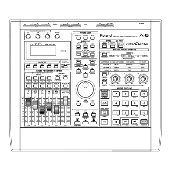
LOCATION OF CONTROLS•••••••••••••••••••••••••••••••••••••••••••••••••••••••••••••••••••••••••••••••••••••••••••••••••2
EXPLODED VIEW•••••••••••••••••••••••••••••••••••••••••••••••••••••••••••••••••••••••••••••••••••••••••••••••••••••••••••••3
BLOCK DIAGRAM•••••••••••••••••••••••••••••••••••••••••••••••••••••••••••••••••••••••••••••••••••••••••••••••••••••••••••••4
PARTS LIST ••••••••••••••••••••••••••••••••••••••••••••••••••••••••••••••••••••••••••••••••••••••••••••••••••••••••••••••••••••5
TEST MODE ••••••••••••••••••••••••••••••••••••••••••••••••••••••••••••••••••••••••••••••••••••••••••••••••••••••••••••••••6~8
SYSTEM SOFTWARE UPDATE••••••••••••••••••••••••••••••••••••••••••••••••••••••••••••••••••••••••••••••••••••••••••••8
CIRCUIT DIAGRAM & BOARD ••••••••••••••••••••••••••••••••••••••••••••••••••••••••••••••••••••••••••••••••••••••••9~15
IC DATA ••••••••••••••••••••••••••••••••••••••••••••••••••••••••••••••••••••••••••••••••••••••••••••••••••••••••••••••••••••••••16
SPECIFICATIONS •••••••••••••••••••••••••••••••••••••••••••••••••••••••••••••••••••••••••••••••••••••••••••••••••••••••••••17
INSTALLING THE ••••••••••••••••••••••••••••••••••••••••••••••••••••••••••••••••••••••••••••••••••••••••••••••••••••••••••••17
PARTS LIST•••••••••••••••••••••••••••••••••••••••••••••••••••••••••••••••••••••••••••••••••••••••••••••••••••••••••••••••••••18
CIRCUIT DIAGRAM & BOARD•••••••••••••••••••••••••••••••••••••••••••••••••••••••••••••••••••••••••••••••••••••••19~20
Copyright c 1998 by ROLAND CORPORATION
All rights reserved. No part of this publication may be reproduced in any form without the written permission of ROLAND CORPORATION.
17059934
A-6
SPECIFICATIONS
A-6 Digital Multi Audio Station Video Canvas
Tracks
Tracks:
V-Tracks:
* One stereo pair of tracks can be recording simultaneously.
Issued by RJA
Maximum Polyphony
4 stereo (total)
Maximum Useful Capacity
16 G bytes:
Audio Data Format
A-6 Original (R-DAC)
Page
Internal Memory
Pad Groups:
Pad Clips:
Projects:
Effect Patches:
Channel Equalizer
3 band parametric (HI, MID, LOW)
(5 channel: Track A -- D, PAD)
Signal Processing
AD Conversion:
DA Conversion:
Internal Processing:
Sample Rate
44.1 kHz
Recording Time (at 2 G bytes, conversion in stereo track)
9 hours approx. (Including Demo Clips on the HDPA6 series hard disk)
* Times may be slightly depending on the times of recording procedure.
Number of Track Clips
Approx. 2,000 clips per 1 project
Synchronization
MIDI MTC/MMC (Master, Slave)
Frequency Response
10 Hz -- 21 kHz (+0/-3 dB)
Nominal Input Level (variable)
MIC:
VCR:
CD:
Input L, R (Available with A6-OP1 is installed.)
(MIC):
(LINE):
Input Impedance
MIC:
VCR:
CD:
Input L, R (Available with A6-OP1 is installed.):
Nominal Output Level
Master Out:
Monitor Out:
Output L, R (Available with A6-OP1 is installed.):
Output Impedance
Master Out:
Monitor Out:
Headphones:
Output L, R (Available with A6-OP1 is installed.):
Recommended Load Impedance
Master Out:
Monitor Out:
Headphones:
Output L, R (Available with A6-OP1 is installed.):
S/N Ratio (Line AD/DA total, IHF-A, typ.)
Master Out:
Monitor Out:
Display
LCD UNIT 69.0 x 25.0 mm (with backlight)
Connectors
MIC In Jack (1/4 inch phone type)
VCR In Jacks L, R (RCA phone type)
CD In Jacks L, R (RCA phone type)
Master Out Jacks L, R (RCA phone type)
Monitor Jacks L, R (RCA phone type)
Headphones Jack (Stereo 1/4 inch phone type)
GPI In Jack (1/4 inch phone type)
MIDI Connectors (IN, OUT/THRU)
* Available with the Multi I/O Expansion "A6-OP1" is installed.
SCSI Connector (DB-25 type)
Digital In Connector (Coaxial type)
Digital Out Connector (Coaxial type)
Input L, R (XLR type, balanced, line/mic selective)
Output L, R (XLR type, balanced)
Power Supply
AC 117 V, AC 230 V or AC 240 V
Power Consumption
16 W (Including internal hard disk)
Dimension
394 (W) x 343 (D) x 99 (H) mm
15-9/16 (H) x 13-9/16 (D) x 3-15/16 (H) inches
Weight
4.1 kg (Excluding internal hard disk and A6-OP1)
9 lbs 1 oz
Accessories
Owner's Manual Set (English)
AC Cord 120V
AC Cord 230V
AC Cord 240VA
AC Cord 240VE
Memo Sheet
Discovery Demo CD (English)
Options
Internal Hard Disk Drive Unit:
Multi I/O Expansion:
Video MIDI Sync Interface:
(0 dBu = 0.775 V rms)
* In the interest of product improvement, the specifications and/or appearance of this unit are subject
to change without prior notice.
Printed in Japan (GF0) (CR)
1
4 stereo
32 stereo (4 stereo tracks x 8 V-Tracks)
2 G bytes (capacity) x 8 (partition)
99
994 (10 pad x 99 group + 4 (favorite))
64
99 (preset) + 99 (user) + 4 (panel)
20 bits, 64 times over sampling
20 bits, 128 times over sampling
24 bits (mixer section)
-50 -- -20 dBu
-10 -- +4 dBu
-10 -- +4 dBu
-50 -- -20 dBu
-10 -- +4 dBu
100 k ohms
47 k ohms
47 k ohms
6 k ohms
-10 dBu
-10 dBu
+4 dBu
2 k ohms
2 k ohms
10 ohms
600 ohms
10 k ohms or greater
10 k ohms or greater
4 -- 600 ohms
10 k ohms or greater
92 dB
92 dB
(#71125145)
(#00894378)
(#00894389)
(#23495124)
(#00907001)
(#17048432)
(#17048434)
HDPA6 Series
A6-OP1
SI-80S
Advertisement
Table of Contents

Subscribe to Our Youtube Channel
Related Manuals for Roland A-6


Summary of Contents for Roland A-6
-
Page 1: Table Of Contents
* In the interest of product improvement, the specifications and/or appearance of this unit are subject to change without prior notice. All rights reserved. No part of this publication may be reproduced in any form without the written permission of ROLAND CORPORATION. 17059934... -
Page 2: Location Of Controls
Oct, 1998 LOCATION OF CONTROLS (A-6 + A6-OP1) SLIDE SWITCH SSSS922N-4C2-1 PIN JACK (01565701) YKC21-3044 WIRING AC ASSY (00458801) (01458878) CANNON JACK CANNON JACK NC3FAH2-0 NC3MAH D-SUB 25PIN CONNECTER (01239890) (00679767) DBLC-J25SAF-20L9F (13429314) A6-OP1 EXP COVER (01564790) REAR PANEL (01562134) -
Page 3: Exploded View
Oct, 1998 EXPLODED VIEW (A-6) [PARTS] PART No. PART NAME 01562089 TOP CASE 01562145 TOP PANEL 01562167 RUBBER SW 71016045 SWITCH BOARD 01562178 HD COVER 71124723 BEAM BOARD 01348490 LCD UNIT RCM6038T-A 70909012 PANEL BOARD 01348501 SUB CHASSIS 71127056 MAIN BOARD... -
Page 4: Block Diagram
Oct, 1998 BLOCK DIAGRAM SWITCH BOARD SWITCH,LED PANEL BOARD INPUT FADER SWITCH , LED Drive UNIT INPUT INPUT A/D/A IC24 D-RAM FLASH-RAM I/F GATE ARRAY AK4520 IC13 TMS418169A LH28F800SUT SLA919FF0J MUTE MIDI MASTER IC35 4053 OUTPUT BOARD INPUT HD6432653 INPUT BA11F A/D/A IC23... -
Page 5: Parts List
Oct, 1998 PARTS LIST 15289105 UPC4570G2-T2 BIPOLAR OP AMP IC25-IC32.IC34.IC36 on MB 15199286 AN78L05M-(E1) REGULATOR IC IC22 on MB 00564690 TC9246F(ELP) IC19 on MB 15289123 M51953AFP-600C RESET IC IC6 on MB 15169550T0 TC74HC138AP CMOS IC1.IC5 on PB 15169556T0 TC74HC574AP CMOS IC3 on PB CONSIDERATIONS ON PARTS ORDERING SAFETY PRECAUTIONS:... -
Page 6: Test Mode
Note: When the Zip drive is to be used during test, connect it each time the button is pressed. "* SW OK!!" appears before turning on the A-6. Set Termination to "ON" and SCSI ID to "6". when all the buttons have been pressed. - Page 7 Install the hard disk drive unit ( equivalent to HDPA6-21 ) section to switch "Fs=32.0kHz" to "Fs= 44.1kHz" on the to the A-6 before start testing. ( Turn off the power when up left of the LCD. installing the hard disk drive unit.)
-
Page 8: System Software Update
(coaxial-type) and A6-OP1's [DIGITAL IN] connector with digital audio cable (coaxial-type). Connect the headphones to A-6's [PHONES] The latest system software of the A-6 is stored to the floppy disk connector. named "A-6 System Ver. 1.xx SMF" as the standard MIDI file When the power of the CD player is OFF, "Unlock"... -
Page 9: Circuit Diagram & Board
Oct, 1998 CIRCUIT BOARD MAIN BOARD ASSY (71127056) View from component side. - Page 10 Oct, 1998 MAIN BOARD ASSY (71127056) View from foil side.
- Page 11 Oct, 1998 PANEL BOARD ASSY (70909012) / MIDI BOARD ASSY (71016034) MIDI BOARD ASSY /CONNECTOR BOARD ASSY (71124767) (71016034) View from component side. CONNECTOR BOARD ASSY (71124767) View from foil side. PANEL BOARD ASSY (70909012)
- Page 12 Oct, 1998 SW BOARD ASSY (71016045) / BEAM BOARD ASSY (71124723) BEAM BOARD ASSY (71124723) SW BOARD ASSY (71016045) View from component side. View from foil side.
- Page 13 Oct, 1998 CIRCUIT DIAGRAM MAIN BOARD ASSY (71127056) TO LCD UNIT TO PANEL BOARD CN1 TO PANEL BOARD CN2 D[0:15] AS,RD,GARD,BRD,HWR,LWR,WAIT0,WAIT1,CLK,RST CS1,CS3,CS[5:7] DRQ0,DRQ1,DRQ_R,IRQ0,IRQ2,IRQ3 C311 100P 100P C300 C312 100P C301 100P C313 100P DAN202 C302 100P C314 100P A[0:23] B4B-PH-K-S C303 100P C315...
- Page 14 Oct, 1998 PANEL BOARD ASSY (70909012) SEL5421E PLAY SEL5221S SEL5221S EFE.A FROM MAIN BOARD CN9 EFE.B LED1 LS[0:7] LED2 100/6.3 LED3 EWAQ1AC10B54 RK09L1140 D230 EWAQ1AC10B54 RK09L1140 RK09L1140 EFE.C SML72423C PROJECT STATUS EFE.A DRAG SHIFT SEL5921A SEL5921A SEL5921A SEL5221S LLCK D231 FROM MAIN BOARD CN11 SML72423C SSEN...
- Page 15 Oct, 1998 CONNECTOR BOARD ASSY (71124767) SWITCH BOARD ASSY (71016045) C N3 RESET RESET DD07 DD07 DD08 DD08 DD06 DD06 DD09 DD09 DD05 DD05 DD10 DD10 LB[0:7] FROM PANEL BOARD CN3 DD04 DD04 DD11 DD11 DD03 DD03 >| BEEP DD12 DD12 DD02 DD02...
-
Page 16: Ic Data
Oct, 1998 IC DATA 16M DRAM HD6432653BA11F (01340201) TMS41816A-60 (01347745) IC7 on MB IC8 on MB PG / CS P5 / ADTRG LCAS PG / CS P5 / SCK UCAS P5 / RxD PC / A P5 / TxD PC / A PF / BREQ PC / A PF / BACK... -
Page 17: A6-Op1
Oct, 1998 INSTALLING THE A6-OP1 A6-OP1 1. Turn off the A-6. Remove all connecting cables from the A-6. 2. Place the A-6 upside down. Remove the bottom cover. 3. Remove the EXP cover from the A-6. 4. Plug in A6-OP1 connector, with a length of the flat cable bent, intothe A-6 main board connector. -
Page 18: Parts List
Oct, 1998 PARTS LIST CONSIDERATIONS ON PARTS ORDERING SAFETY PRECAUTIONS: When ordering any parts listed in the parts list, please specify the following items in the order sheet. The parts marked have PART NUMBER DESCRIPTION MODEL NUMBER safety-related characteristics. 22575241 Sharp Key C-20/50 Use only listed parts for... -
Page 19: Circuit Diagram & Board
Oct, 1998 CIRCUIT BOARD (A6-OP1) A6-OP1 I/O BOARD ASSY (71126790) View from component side. View from foil side. - Page 20 Oct, 1998 CIRCUIT DIAGRAM SCSI A6-OP1 I/O BOARD ASSY (71126790) DBLC-J25SAF-20L9F 220/6.3 SB20-03P UBDA CKA2 CKA1 LRCK LBIT YKC21-3044 FR32 TC7WU04F DATA CTG3 DIGITAL VLDV CTG2 EMPH CTG1 220/6.3 BLM41P750S COPY PT-10 220/6.3 TC7WU04F TC9271F YKC21-3044 DIGITAL DIN1 C103 DIN2 HCU04 HCU04 220/6.3...
Need help?
Do you have a question about the A-6 and is the answer not in the manual?
Questions and answers