
Subscribe to Our Youtube Channel
Related Manuals for GE GLM064


Summary of Contents for GE GLM064
-
Page 1: User Manual
Automation & Controls Programmable Control Products PACSystems* PROFINET PACSystems* Ethernet Switch GLM Series User Manual GFK-3030 Managed Industrial Ethernet Switches User Manual GFK-3030 December 2017 For Public Disclosure... - Page 2 Changes, modifications, and/or improvements to equipment and specifications are made periodically and these changes may or may not be reflected herein. It is understood that GE may make changes, modifications, or improvements to the equipment referenced herein or to the document itself at any time. This document is intended for trained personnel familiar with the GE products referenced herein.
- Page 3 Online technical support and GlobalCare www.geautomation.com/support Additional information www.geautomation.com Solution Provider solutionprovider.ip@ge.com Technical Support If you have technical problems that cannot be resolved with the information in this manual, please contact us by telephone or email, or on the web at www.geautomation.com/support...
-
Page 4: Table Of Contents
Table of Contents PACSystems* Ethernet Switch GLM Series User Manual GFK-3030 Table of Contents ................................i Table of Figures ................................iv Chapter 1 Introduction ..............................1 Revisions in this Manual ........................... 2 PACSystems Documentation ........................2 Chapter 2 Overview ..............................3 System Overview ............................ - Page 5 Contents Chapter 4 Configuration ............................17 Import the GSDML file ..........................18 Associating the IO-Device with its Controller ..................21 PROFINET Cyclic I/O Data ........................23 Slot 1: Device Status ..............................24 Slot 2: Port Status ..............................24 Slot 3: Port Alarm & Port Settings & Status ....................25 Slot 4: MRP Group 1 Status ..........................
- Page 6 Contents Summary of Commands Descriptions....................48 Command Descriptions .......................... 49 Initialize Mode Commands ..........................49 Enable Mode Commands ............................. 50 Configure Mode Commands..........................71 VLAN Mode Commands ............................91 Interface VLAN Mode Commands ........................94 RingV2 Group Mode Commands ........................97 Spanning Tree Commands ..........................
-
Page 7: Table Of Figures
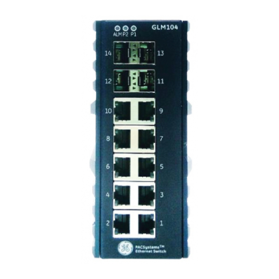
Contents Table of Figures Figure 1: GLM064 ........................................1 Figure 2: GLM082 ........................................1 Figure 3: GLM104 ........................................1 Figure 4: Typical PROFINET System with GLM Switches ..........................3 Figure 5: GLM Switch Bottom Panel...................................5 Figure 6: Front-Panel LEDs .....................................6 Figure 7: DIN-Rail Mounting ....................................7 Figure 8: Panel-Mounting ......................................8... -
Page 8: Chapter 1 Introduction
Chapter 1 Introduction Figure 1: GLM064 Figure 3: GLM104 Figure 2: GLM082 The PACSystems GLM series Industrial Ethernet Switches deliver high quality Ethernet operation over a wide temperature range and can tolerate an extended power input range. These switches are ideal for harsh environments and mission critical applications. -
Page 9: Revisions In This Manual
GFK-2737 In addition to these manuals, datasheets and product update documents describe individual modules and product revisions. The most recent PACSystems documentation is available on the GE Intelligent Platforms support website http://geautomation.com/support. PACSystems PROFINET Managed Industrial Ethernet Switches User Manual... -
Page 10: Chapter 2 Overview
Chapter 2 Overview System Overview IO-Devices on a PROFINET Network GLM Switches are treated as PROFINET-IO devices. The host PLC will therefore use an embedded PROFINET port or a PNC001 PROFINET IO-Controller Module. All physical connections use standard Ethernet connectors (RJ45 or SFP). -
Page 11: Ethernet Devices On An Ethernet Network
Chapter 2. Overview Ethernet Devices on an Ethernet Network The GLM switches contain a number of features which cannot be accessed over PROFINET, but are available over Ethernet. The user may choose to install a separate Ethernet network for this purpose, or run both PROFINET and Ethernet on the same physical network. -
Page 12: Glm Product Differentiation
Chapter 2. Overview GLM Product Differentiation Product differentiation within the GLM Series of products lies in the number of standard RJ45 Ethernet connections and Small Form-Factor Pluggable (SFP) ports offered, as follows: Product Number of RJ45 Ports Number of SFP Ports Appearance IC086GLM064 Figure 1... -
Page 13: Glm Leds
Chapter 2. Overview GLM LEDS Figure 6: Front-Panel LEDs Each GLM Switch product is equipped with a common set of LEDs, as shown in Figure 6: • One LED for each of the two permitted power supply inputs (P1 and P2) •... -
Page 14: Chapter 3 Installation
Chapter 3 Installation Mounting The GLM switches may be DIN-rail mounted or panel-mounted. DIN-Rail Mounting Figure 7: DIN-Rail Mounting Attach the DIN-Rail bracket to the mounting surface with the bracket and screws in the included accessory kit. Hook the top edge of the DIN-Rail latch attached to the GLM switch over the top edge of the DIN rail. Push the bottom of the GLM unit towards the DIN Rail until the bottom latch snaps into place. -
Page 15: Panel Mounting
Chapter 3. Installation Panel Mounting Figure 8: Panel-Mounting Prepare two pilot holes in the mounting surface 172mm apart, per Figure 8. Attach the top and bottom panel-mounting plates to the rear of the GLM switch chassis using the screws provided in the accessory kit. Secure the GLM switch to the mounting surface with a pair of M4 machine screws. -
Page 16: Power Connection
The P1 and P2 LEDs on the front panel indicate the status of these two power supply inputs, as shown in Section 3.6, LED Operation. GLM Switch Current Draw The maximum current draw at 24Vdc (nominal) for each of the devices is shown below: Device Max Current @ 24Vdc (nominal) GLM064 580mA GLM082 521mA GLM104 709mA Note: Each DC power input should be connected to a suitably-fused power supply. -
Page 17: Grounding
Chapter 3. Installation Grounding Each GLM switch must be properly grounded for optimal performance. A ground screw (chassis ground) is provided as part of the bottom panel, as shown below. Loosen the ground screw, insert the stripped end of the ground strap, then tighten the ground screw to secure the ground strap in place. -
Page 18: Alarm Relay Output
Chapter 3. Installation Alarm Relay Output The Alarm Relay Output is located on the two terminals in the center of the 6-pin terminal strip on the bottom panel. Figure 11: Alarm Relay Output The Alarm Relay Output may be connected to an external device. It is a Normally Open Relay. The state of the Alarm Relay is indicated on the ALM LED, as documented in Section 3.6, LED Operation. -
Page 19: Ethernet Connections
Chapter 3. Installation Ethernet Connections Ethernet connections use either RJ45 (electrical) or mini-GBIC (optical) interfaces. All Ethernet connections are located on the faceplate. Refer to Figure 1 through Figure 3.The number and type available for each product in the GLM series is discussed in Section 2.1.3, GLM System Capabilities. The activity and speed of each port is indicated separately, as documented in Section 3.6, LED Operation. -
Page 20: Sfp Connections
Chapter 3. Installation SFP Connections GLM Switches provide SFP connections using an optical (mini-GBIC) interface. For example, on GLM082, Ports 9 and 10 are SFP ports. Figure 15: Attach Fiber-Optic Cables to Installed SFP Figure 14: Fiber-Optic Cable with LC Duplex Connectors Socket Prepare a suitable SFP module and install it into the GLM optical port. -
Page 21: Led Operation
Chapter 3. Installation LED Operation STATE Description On Green P1 input power is within specification P1 power line is disconnected or supply power is not within specifications On Green P2 input power is within specification P2 power line is disconnected or supply power is not within specifications On Red Alarm contact energized... -
Page 22: System Reset
Chapter 3. Installation System Reset In the event a GLM switch becomes unresponsive, press the recessed Reset button located on the bottom panel. The reset pushbutton reboots the GLM switch without the need to remove power from that switch. Resetting a switch is normally not required. The Reset button is recessed in order to avoid accidental use. GFK-3030 December 2017... -
Page 23: Console Connection
Chapter 3. Installation Console Connection The Console port, located on the bottom panel (Figure 16), is intended for administrative functions, and its use is optional. It uses a terminal emulator or a computer with terminal emulation software, connected as follows: •... -
Page 24: Chapter 4 Configuration
Chapter 4 Configuration Configuration is accomplished using Proficy Machine Edition (PME). Each GLM device has a corresponding GSDML file, which must also be imported. The GLM Switch Device is always used as a PROFINET IO-Device. Select a suitable PROFINET Controller within the CPU and “add”... -
Page 25: Import The Gsdml File
Chapter 4. Configuration Import the GSDML file Browse to the folder containing the GSDML file, then import it using the Toolchest feature of PME, as shown below. Alternately, use the Have GSDML button shown in Figure 25, and perform the import as configuration progresses. -
Page 26: Figure 20: Select Profinet Device
Chapter 4. Configuration Since the GLM Switch is to be used as a PROFINET Device, select PROFINET Devices from the drop-down list (Figure 20). Figure 20: Select PROFINET Device Right click on the PROFINET Devices line item. At the bottom of the resulting drop-down menu, under Assistants, select the Import GSDML command. -
Page 27: Figure 22: Browse To Folder And Select Gsdml File For Import
Chapter 4. Configuration The resulting dialog box allows you to browse to the desired folder and select the GSDML file. Figure 22: Browse to Folder and Select GSDML file for Import The Toolchest now displays the newly-added device: Figure 23: Toolchest Displays Newly-Added Device PACSystems PROFINET Managed Industrial Ethernet Switches User Manual GFK-3030... -
Page 28: Associating The Io-Device With Its Controller
Chapter 4. Configuration Associating the IO-Device with its Controller Each GLM Switch device has to be associated with the PROFINET Controller which will be controlling and monitoring it. Figure 24 shows that the PNC001 module located in Slot 6 of Rack 0 (the Main CPU Rack) has been selected. -
Page 29: Figure 26: Io-Device Installed Under Pnc001
Chapter 4. Configuration Once selected, the IO-Device will display as having been installed under the previously selected PNC001. Figure 26: IO-Device Installed Under PNC001 Also note that the constituent ports of the new IO-Device are also displayed in Figure 26. The data from the associated slots (shown in Figure 26) is treated as Cyclic I/O Data (RTC) by the PROFINET Controller. -
Page 30: Profinet Cyclic I/O Data
8, plus 1. In the case of slot 3, where there are matching input and output settings, GE recommends selecting the same %I and %Q references, as this will avoid confusion when debugging and in project documentation. For instance, if %I00129 is used for the Port Alarm Inputs, then use %Q00129 for the Port Alarm Outputs. -
Page 31: Slot 1: Device Status
Chapter 4. Configuration Slot 1: Device Status Category Direction Byte# Bit# Name Description 0=No Alarm (ALM Relay Open), Alarm Status 1=Alarm Detected (ALM Relay Closed) Power 1 Status 0=PWR1 not OK, 1=PWR1 OK Device Data Input (Slot 1) Power 2 Status 0=PWR2 not OK, 1=PWR2 OK Ring Enabled/Disabled 0=Disabled, 1=Enabled... -
Page 32: Slot 3: Port Alarm & Port Settings & Status
Chapter 4. Configuration Slot 3: Port Alarm & Port Settings & Status Output Input Description Category Direction Byte# Bit# Name Description 0=Alarm Disabled, 0=No Alarm Port 1 Alarm 1=Alarm Enabled 1=Alarm Condition Detected 0=Alarm Disabled, 0=No Alarm Port 2 Alarm 1=Alarm Enabled 1=Alarm Condition Detected 0=Alarm Disabled,... - Page 33 Chapter 4. Configuration Category Direction Byte# Bit# Name Output Description Input Description 0=Enable Port, 0=Port Enabled Port 1 Admin 1=Disable Port 1=Port Disabled 0=Enable Port, 0=Port Enabled Port 2 Admin 1=Disable Port 1=Port Disabled 0=Enable Port, 0=Port Enabled Port 3 Admin 1=Disable Port 1=Port Disabled 0=Enable Port,...
-
Page 34: Slot 4: Mrp Group 1 Status
Chapter 4. Configuration Slot 4: MRP Group 1 Status Category Direction Byte# Bit# Name Description MRP Group 1 Mode 0=MRP Disabled, 1=MRP Enabled MRP Group 1 Input (Slot 4) MRP Group 1 Role 0=MRP Client, 1=MRP Master 0=Not MRP-G1 Ring Port Port 1 MRP-G1 Status 1=MRP-G1 Ring Port 0=Not MRP-G1 Ring Port... -
Page 35: Slot 5: Mrp Group 2 Status
Chapter 4. Configuration Slot 5: MRP Group 2 Status Category Direction Byte# Bit# Name Description MRP Group 2 Mode 0=MRP Disabled, 1=MRP Enabled MRP Group 2 Input (Slot 5) MRP Group 2 Role 0=MRP Client, 1=MRP Master 0=Not MRP-G2 Ring Port Port 1 MRP-G2 Status 1=MRP-G2 Ring Port 0=Not MRP-G2 Ring Port... -
Page 36: Slot 6: Ring Group 1 Status
Chapter 4. Configuration Slot 6: Ring Group 1 Status Category Direction Byte# Bit# Name Description Ring Group 1 Mode 0=Ring Disabled, 1=Ring Enabled Ring Group 1 Input Ring Group 1 Role 0=Ring Slave, 1=Ring Master (Slot 6) Ring Status 0=Failure, 1=Normal Condition 0…3 Ring Port 1 Number Port ID number (1 thru 14) -
Page 37: Profinet Acyclic I/O Data
Chapter 4. Configuration PROFINET Acyclic I/O Data The GLM Switches also support PROFINET Acyclic I/O Data (RTA). Data of this type has been mapped to the sub-slots as indicated in this section, and may be retrieved via the assigned %I references. Acyclic Device Data –Subslot 0 Byte Name Access... - Page 38 Chapter 4. Configuration Byte Name Access Value Description Not supported Ring-2 Mode read-only Enabled (config value) Disabled Not supported Ring Master Ring Slave Ring-2 Role read-only Coupling Primary Coupling Backup Dual Homing Not supported Disabled Ring-2 State read-only Normal Failed Not supported Ring-3 Mode read-only...
-
Page 39: Acyclic Port Data - Subslot 1
Chapter 4. Configuration Acyclic Port Data – Subslot 1 Byte Name Access Value Output Description Input Description Port Alarm read-write Do not send alarm No Port Alarm Send alarm when port link down Port Alarm Detected Port Setting read-write Not supported Not supported State Port Link State... -
Page 40: Acyclic Mrp Group 1 Data - Subslot 2
Chapter 4. Configuration Acyclic MRP Group 1 Data – Subslot 2 Byte Name Access Value Output Description Input Description MRP Mode read-write Disable MRP MRP Disabled Enable MRP (Default) MRP Enabled MRP Role read-write MRC (Default) Assigned Port ID of Ring Port1 Ring Port1 of MRP read-write Port ID... -
Page 41: Acyclic Ring Group 1 Data - Subslot 4
Chapter 4. Configuration Acyclic Ring Group 1 Data – Subslot 4 Byte Name Access Value Output Description Input Description Ring Mode read-write Disable Ring (Default) Ring Disabled Enable Ring Ring Enabled Ring Role read-write Slave (Default) Slave Master Master Ring Port1 read-write Assigned Port ID of Ring Port1 Port ID... -
Page 42: Acyclic Mrpe Group 1 Data - Subslot 5
Chapter 4. Configuration Acyclic MRPe Group 1 Data – Subslot 5 Byte Name Access Value Output Description Input Description MRPe Mode read-write Disable MRPe (Default) MRPe Disabled Enable MRPe MRPe Enabled MRPe Role read-write Slave (Default) Slave Master Master Port ID of MRPe port MRPe Port read-write Port ID... -
Page 43: Assigning Device Name And Ip Address
Chapter 4. Configuration Assigning Device Name and IP Address In order to communicate with the newly-added IO-Device, it is necessary to provide it with a unique Device Name and a unique IP Address. This is performed using the Discovery and Configuration Protocol Tool (DCP). Figure 28: Properties of IO-Device As shown in Figure 28, you will need to drill down to the Properties of the highlighted IO-Device. -
Page 44: Mrp Settings For Io-Devices
Chapter 4. Configuration MRP Settings for IO-Devices Media Redundancy Protocol (MRP) is supported by PACSystems PROFINET Controllers. Refer to the PACSystems RX3i & RSTi-EP PROFINET I/O Controller Manual, GFK-2571, To access the MRP parameters associated with a target IO-Device, display the hardware configuration in PME, then double-click on the IO-Device of interest (Figure 30). -
Page 45: Download From Pme To Cpu
Chapter 4. Configuration Download from PME to CPU Once all the devices have been configured, download the resulting configuration from PME to the host CPU. The CPU will then distribute the configuration elements to its connected devices. Hot Standby CPU Redundancy Considerations The Properties of IO-Devices need to be synchronized between the Primary and Secondary CPUs in a Hot Standby CPU Redundancy System. -
Page 46: Discovery Tool
Chapter 4. Configuration Discovery Tool If desired, the operator may use the Launch Discovery Tool of PME to automatically detect all connected network devices. This operation may only be performed once all network devices have been interconnected and powered up. Figure 33: Launch Discovery Tool As shown in Figure 33, select the network controlling device (here the PNC001 in Slot 6 is highlighted). -
Page 47: Figure 35: Listing Of All Detected Devices
Chapter 4. Configuration Figure 35: Listing of all Detected Devices If devices are missing due to incorrect cabling or not having been powered up, correct those situations, then click on the Refresh Device List button. PACSystems PROFINET Managed Industrial Ethernet Switches User Manual GFK-3030... -
Page 48: Chapter 5 Diagnostics
Chapter 5 Diagnostics The GLM Switches support one alarm per port, plus an independent alarm for each power input circuit (PWR1 and PWR2), and an Alarm Status bit that tracks the state of the ALM relay. There are also status bits relating to MRP set-up. -
Page 49: Setting Up And Sensing Alarms
Chapter 5. Diagnostics Setting up and Sensing Alarms Use PME to assign bits in the %Q output table to control whether GLM alarms for a target device will be enabled or disabled. These are shown as the Port Alarm Outputs in Figure 36. The Alarm Enabled bits are contiguous and must be assigned a starting location in %Q on a byte boundary. -
Page 50: Power Alarm
Chapter 5. Diagnostics Power Alarm As documented in Section 3.2, Power Connection, there are two independent power connections, PWR1 and PWR2. In the event one of these is powered up and is capable of energizing the target GLM switch device, it is then possible for that GLM Switch device to sense that the alternate Power Supply Input is within specification, or otherwise. -
Page 51: External Alarm Circuit
Chapter 5. Diagnostics External Alarm Circuit The two ALM contacts in the 6-pin terminal strip located in the bottom panel may be used to drive an external alarm circuit, as diagrammed in Figure 38. The Alarm Relay is Normally Open, and closes in the event of an alarm condition. -
Page 52: Appendix A Command Language Interface (Cli)
Appendix A Command Language Interface (CLI) Command Language Interface (CLI) is the protocol used by the Console. For security reasons, use of the Console is discouraged. Information is supplied in this appendix in case the user chooses to use this interface. A-1 Operator Interface Login Access to the Switch is protected by a logon security system. -
Page 53: Execution Modes
Appendix A. Command Language Interface (CLI) Figure 40: Telnet Login Screen Execution Modes The CLI contains several execution modes. Users will see different set of commands under different execution modes. The following table lists all the execution modes and their purposes. When users enter a certain execution mode, the corresponding mode prompt will be displayed automatically on the screen. -
Page 54: Terminal Key Function
Appendix A. Command Language Interface (CLI) Terminal Key Function Following is the list of all the terminal keys and their functions. ENTER CTRL-M Run a CLI config script Tab completion. CTRL-I If tab is pressed after a non-whitespace character, complete the word before the Tab. If tab is pressed after a whitespace character, complete the next word. -
Page 55: A-2 Summary Of Commands Descriptions
Appendix A. Command Language Interface (CLI) A-2 Summary of Commands Descriptions A-3.1 Initialize Mode Commands A-3.2 Enable Mode Commands A-3.3 Configure Mode Commands A-3.4 VLAN Mode Commands A-3.5 Interface VLAN Mode Commands A-3.6 Ring Group Mode Commands A-3.7 Spanning Tree Configure Commands A-3.8 sFlow Configure Command A-3.9... -
Page 56: A-3 Command Descriptions
Appendix A. Command Language Interface (CLI) A-3 Command Descriptions Initialize Mode Commands The commands in this section (except ‘enable’ command) can be executed under all command modes. These commands are global commands. A.3.1.1 exit Description Exit current mode and quit CLI. Syntax exit Parameter... -
Page 57: Enable Mode Commands
Appendix A. Command Language Interface (CLI) Enable Mode Commands All the “show - -” commands in this section can also be executed under any other command mode except Initialize Mode. A.3.2.1 configure terminal Description Enter configuration mode. Syntax configure Parameter None A.3.2.2 disable... - Page 58 Appendix A. Command Language Interface (CLI) A.3.2.4 show access-list Description Access list show access-list [ interface [ ( <port_type> [ <v_port_type_list> ] ) ] ] [ rate-limiter [ Syntax <rate_limiter_list> ] ] [ ace statistics [ <ace_list> ] ] show access-list ace-status [ static ] [ link-oam ] [ loop-protect ] [ dhcp ] [ ptp ] [ upnp ] [ arp- inspection ] [ mep ] [ ipmc ] [ ip-source-guard ] [ ip-mgmt ] [ conflicts ] [ switch <switch_list>...
- Page 59 Appendix A. Command Language Interface (CLI) A.3.2.7 show cpu-load Description CPU LOAD Syntax show cpu-load Parameter A.3.2.8 show green-ethernet Description Green Ethernet Syntax show green-ethernet [ interface ( <port_type> [ <port_list> ] ) ] show green-ethernet eee [ interface ( <port_type> [ <port_list> ] ) ] show green-ethernet energy-detect [ interface ( <port_type>...
- Page 60 Appendix A. Command Language Interface (CLI) A.3.2.10 show ipmc Description IPMC information Syntax show ipmc profile [ <profile_name> ] [ detail ] show ipmc range [ <entry_name> ] Parameter Name Description profile IPMC profile configuration range A range of IPv4/IPv6 multicast addresses for the profile profile_name <ProfileName : word16>...
- Page 61 Appendix A. Command Language Interface (CLI) A.3.2.14 show logging Description Logging information Syntax show logging <log_id> [ switch <switch_list> ] show logging [ info ] [ warning ] [ error ] [ switch <switch_list> ] Parameter Name Description log_id <logging_id: 1-4294967295> Logging ID error Error info...
- Page 62 Appendix A. Command Language Interface (CLI) A.3.2.20 show running-config interface vlan Description Show default running configuration. Syntax show running-config interface vlan <vlan_list> [ all-defaults] Parameter None A.3.2.21 show running-config all-defautls Description Show all default setting Syntax show running-config [ all-defaults ] Parameter None A.3.2.22...
- Page 63 Appendix A. Command Language Interface (CLI) A.3.2.24 show running-config vlan Description VLAN information Syntax show running-config vlan <list> [ all-defaults ] Parameter Name Description list <vlan_list> List of VLAN numbers all-defaults Include most/all default values A.3.2.25 show version Description Show firmware hardware and software status update status. Syntax show version Parameter...
- Page 64 Appendix A. Command Language Interface (CLI) A.3.2.31 show mac address table conf Description User added static mac addresses show mac address-table [ conf | static | aging-time | { { learning | count } [ interface ( Syntax <port_type> [ <v_port_type_list> ] ) ] } | { address <v_mac_addr> [ vlan <v_vlan_id> ] } | vlan <v_vlan_id_1>...
- Page 65 Appendix A. Command Language Interface (CLI) A.3.2.36 show mac address vlan <vlanid> Description Show MAC learning table per VLAN index. Syntax show mac address-table { learning | count } vlan <vlan_id> Parameter Name Description <vlanid> Valid values: 1~4094 Type: Mandatory A.3.2.37 show mvr Description...
- Page 66 Appendix A. Command Language Interface (CLI) A.3.2.40 show fdbstatic vlan <vlanid> Description Show static MAC forwarding table per VLAN index. Syntax show mac address-table { learning | count } vlan <vlanid> Parameter Name Description <vlanid> Valid values: 1~4094 Type: Mandatory A.3.2.41 show interface port <...
- Page 67 Appendix A. Command Language Interface (CLI) A.3.2.44 show port-security Description Port security Syntax show port-security Parameter Name Description port Show MAC Addresses learned by Port Security switch Show Port Security status interface Interface port_type GigabitEthernet, 1 Gigabit Ethernet Port v_port_type_list PORT_LIST, Port list in 1/1-8 A.3.2.45 show profile alarm...
- Page 68 Appendix A. Command Language Interface (CLI) A.3.2.47 show snmp Description SNMP information Syntax show snmp show snmp access [ <group_name> { v1 | v2c | v3 | any } { auth | noauth | priv } ] show snmp community v3 [ <community> ] show snmp host [ <conf_name>...
- Page 69 Appendix A. Command Language Interface (CLI) A.3.2.48 show spanning-tree Description System Wide Spanning Tree Setting/Status. Syntax show spanning-tree [ summary | active | { interface ( <port_type> [ <v_port_type_list> ] ) } | { detailed [ interface ( <port_type> [ <v_port_type_list_1> ] ) ] } | { mst [ configuration | { <instance>...
- Page 70 Appendix A. Command Language Interface (CLI) A.3.2.52 show vlan name Description Show bridge port member set/status per VLAN name ( 32 words ). Syntax show vlan name <vword32> Parameter Name Description < vword32> Valid values: 32 words Type: Mandatory. A.3.2.53 show vlan brief Description VLAN summary information...
- Page 71 Appendix A. Command Language Interface (CLI) A.3.2.56 show vlan protocol Description Protocol-based VLAN status Syntax show vlan protocol [ eth2 { <etype> | arp | ip | ipx | at } ] [ snap { <oui> | rfc-1042 | snap-8021h } <pid> ] [ llc <dsap> <ssap> ] Parameter Name Description...
- Page 72 Appendix A. Command Language Interface (CLI) A.3.2.58 show qos-queue-mapping Description Show CoS queue mapping table. Syntax show qos maps Parameter None A.3.2.59 show interface ports <portNo> priority Description Show QoS per gigabit port. Syntax show interface <port_type> [ <port_type_list> ] statistics { priority [ <0~7> ] } Parameter Name Description...
- Page 73 Appendix A. Command Language Interface (CLI) A.3.2.64 show pvlan isolation [ interface <port_type> [ <port_type_list>]] Description Show all port isolation information. Syntax show pvlan isolation [ interface <port_type> [ <port_type_list> ] ] Parameter None Name Description <port_type> Port type in Fast, Giga or Tengiga ethernet <portNo>...
- Page 74 Appendix A. Command Language Interface (CLI) A.3.2.68 show qos maps Description MAPS show qos maps { maps [ dscp-cos ] [ dscp-ingress-translation ] [ dscp-classify ] [ cos- Syntax dscp ] [ dscp-egress-translation ] } Parameter Name Description cos-dscp Map for cos to dscp dscp-classify Map for dscp classify enable dscp-cos...
- Page 75 Appendix A. Command Language Interface (CLI) A.3.2.72 show ringv2 Description Show ring protect information Syntax show ring Parameter None A.3.2.73 show rmon Description Syntax show rmon alarm [ <id_list> ] show rmon event [ <id_list> ] show rmon history [ <id_list> ] show rmon statistics [ <id_list>...
- Page 76 Appendix A. Command Language Interface (CLI) A.3.2.77 show interface vlan <vlanid> Description Show VLAN interface information of specify VLAN. Syntax show interface vlan <vlanid> Parameter Name Description <vlanid> VLAN ID. Valid values: 1 ~ 4094 Type: Mandatory A.3.2.78 show protocol-vlan Description Show protocol based VLAN information for all entries.
- Page 77 Appendix A. Command Language Interface (CLI) A.3.2.84 show rfc2544 profile [ <word32> ] Description show rfc2544 profile name Syntax show rfc2544 profile [ <word32> ] Parameter Name Description <word32> rfc2544 profile name A.3.2.85 show voice Description Vlan for voice traffic Syntax show voice vlan [ oui <oui>...
-
Page 78: Configure Mode Commands
Appendix A. Command Language Interface (CLI) Configure Mode Commands Commands that can be executed under Configure Mode. A.3.3.1 interface gigabit <portNo> Description Gigabit Ethernet interface. (enter gigabit interface mode) Syntax interface gigabit <portNo> Parameter Name Description <portNo> Valid values: 1 ~ 10 Type: Mandatory A.3.3.2 interface vlan <vlanid>... - Page 79 Appendix A. Command Language Interface (CLI) A.3.3.6 aggregation mode Description Traffic distribution mode Syntax aggregation mode { dmac | ip | port | smac } Parameter Name Description dmac Destination MAC affects the distribution IP address affects the distribution port IP port affects the distribution smac Source MAC affects the distribution...
- Page 80 Appendix A. Command Language Interface (CLI) A.3.3.11 ntp server <1-5> ip-address <ip> Description Set NTP server address. Syntax ntp server <1-5> ip-address { <ipv4_ucast> | <ipv6_ucast> | <hostname> } Parameter Name Description <1-5> index number <ipv4> Type: Mandatory <ipv6 > <hostname>...
- Page 81 Appendix A. Command Language Interface (CLI) A.3.3.14 account add <username> Description Add an account. Syntax username <word31> privilege <0-15> password encrypted <word4-44> Parameter Name Description Valid values: 1 ~ 31 characters < word31> Type: Mandatory Valid values: 0 ~ 15 <0-15>...
- Page 82 Appendix A. Command Language Interface (CLI) A.3.3.18 clearipigmp snoopingstatistics Description clear ipigmpsnoopingstatisti Syntax clear ipigmp snooping [ vlan<vlan_list> ] statistics Parameter Name Description vlan_list VLAN list. A.3.3.19 clear logging Description clear logging Syntax clear logging [ info ] [ warning ] [ error ] [ switch <switch_list> ] Parameter Name Description...
- Page 83 Appendix A. Command Language Interface (CLI) A.3.3.24 Description To run exec commands in config mode Syntax do <line> Parameter Name Description <line> Exec Command A.3.3.25 duplex Description Set duplex mode Syntax duplex { half | full | auto [ half | full ] } Parameter Name Description...
- Page 84 Appendix A. Command Language Interface (CLI) A.3.3.29 frame-sizes Description Select the frame sizes that the enabled tests will loop through Syntax frame-sizes { [ 64 ] [ 128 ] [ 256 ] [ 512 ] [ 1024 ] [ 1280 ] [ 1518 ] [ 2000 ] [ 9600 ] } Parameter Name Description...
- Page 85 Appendix A. Command Language Interface (CLI) A.3.3.34 iparp inspection Description iparp inspection Syntax iparp inspection Parameter A.3.3.35 Ip arp inspection translate Description IP ARP inspection entry interface configuration Syntax ip arp inspection translate [ interface <port_type><port_type_id><vlan_id><mac_ucast><ipv4_ucast> ] Parameter Name Description port_type Port type in Fast, Giga or Tengigaethernet port_type_id...
- Page 86 Appendix A. Command Language Interface (CLI) A.3.3.39 ip http secure-redirect Description IP http secure-redirect Syntax ip http secure-redirect Parameter A.3.3.40 ip http secure-server Description IP Secure HTTP web server Syntax ip http secure-server Parameter A.3.3.41 ip source binding interface Description IP source binding entry interface configuration Ip source binding interface <port_type>...
- Page 87 Appendix A. Command Language Interface (CLI) A.3.3.44 ip route Description IP Route Syntax ip route <v_ipv4_addr> <v_ipv4_netmask> <v_ipv4_gw> Parameter Name Description v_ipv4_addr Network v_ipv4_netmask Netmask v_ipv4_gw Gateway A.3.3.45 ip routing Description IP routing Syntax ip routing Parameter A.3.3.46 ip verify Description IP verify Syntax...
- Page 88 Appendix A. Command Language Interface (CLI) A.3.3.49 LACP Description LACP system priority Syntax lacp system-priority <v_1_to_65535> Parameter Name Description system-priority System priority <v_1_to_65535> Priority value, lower means higher priority A.3.3.50 line Description Console terminal control Syntax line { <0~16> | console 0 | vty <0~15> } Parameter Name Description...
- Page 89 Appendix A. Command Language Interface (CLI) A.3.3.54 logout Description System logout Syntax logout Parameter A.3.3.55 mac address-table aging-time Description MAC table entries/configuration Syntax mac address-table aging-time <v_0_10_to_1000000> Parameter Name Description <v_0_10_to_1000000> Aging time in seconds, 0 disables aging A.3.3.56 mac address-table static Description MAC table entries/configuration Syntax...
- Page 90 Appendix A. Command Language Interface (CLI) A.3.3.59 ping Description The ping function Syntax ping { ip | ipv6 } Parameter Name Description IP (ICMP) echo ipv6 IPv6 (ICMPv6) echo A.3.3.60 port-security Description Port security Syntax port-security [aging] [time <v_10_to_10000000>] Parameter Name Description aging...
- Page 91 Appendix A. Command Language Interface (CLI) A.3.3.63 rmon Description RMON Syntax rmon {alarm | event} Parameter Name Description alarm Configure an RMON alarm event Configure an RMON event A.3.3.64 rmon alarm Description RMON Alarm Syntax rmon alarm <id> <oid_str> <interval> { absolute | delta } rising-threshold <rising_threshold> [ <rising_event_id>...
- Page 92 Appendix A. Command Language Interface (CLI) A.3.3.65 rmon alarm Description RMON Event Syntax rmon event <id> [ log ] [ trap <community> ] { [ description <description> ] } Parameter Name Description description Specify a description of the event Generate RMON log when the event fires trap Generate SNMP trap when the event fires A.3.3.66...
- Page 93 Appendix A. Command Language Interface (CLI) A.3.3.69 vlan disable <vlanid> Description Delete VLAN memberset/setting. Syntax vlan disable <vlanid> Parameter Name Description <vlanid> Valid values: 1 ~ 4094 Type: Mandatory A.3.3.70 aging <time> Description Configure aging time for a bridge port. Syntax aging <time>...
- Page 94 Appendix A. Command Language Interface (CLI) A.3.3.74 monitor destination interface Description The destination port. That is the port that trafficed should be mirrored to. Syntax monitor destination interface <port_type> <port_type_id> Parameter Name Description <port_type Port type <port_type_id> Port Number A.3.3.75 monitor source interface Description Mirror Interface traffic...
- Page 95 Appendix A. Command Language Interface (CLI) A.3.3.78 traps Description trap event configuration Syntax traps [ aaa authentication ] [ system [ coldstart ] [ warmstart ] ] [ switch [ stp ] [ rmon ] ] Parameter Name Description aaa authentication AAA authentication fail event coldstart Cold start event...
- Page 96 Appendix A. Command Language Interface (CLI) A.3.3.82 username Description User account Syntax username <username> privilege <priv> password encrypted <encry_password> username <username> privilege <priv> password none username <username> privilege <priv> password unencrypted <password> Parameter Name Description <Username : word31> User name allows letters, numbers and username underscores privilege...
- Page 97 Appendix A. Command Language Interface (CLI) A.3.3.84 flow-control {enable|disble} Description Enable/Disable flow-control. Syntax flow-control {enable|disble} Parameter Name Description enable Enable flow-control. disable Disable flow-control. A.3.3.85 speed Description Configure gigabit Ethernet speed and Copper/SFP for gigabit port 7~8. (port1~6 Only support copper, no SFP) (port 9, 10 only support auto) Syntax speed {auto|full-l000mbps|full-100mbps|full-10mbps|half-100mbps|half-10mbps}...
-
Page 98: Vlan Mode Commands
Appendix A. Command Language Interface (CLI) VLAN Mode Commands A.3.4.1 vlan Description VLAN commands Syntax vlan <vlan_list> Parameter Name Description vlan_lis ISL VLAN IDs 1~4095 A.3.4.2 vlan ethertype s-custom-port Description Vlan Ether type for custom S-ports configuration Syntax vlan ethertype s-custom-port <0x0600-0xffff> Parameter Name Description... - Page 99 Appendix A. Command Language Interface (CLI) A.3.4.5 switchport access vlan Description Set switch access mode of the interface Syntax switchport access vlan <vlan_id> Parameter Name Description vlan_id VLAN ID of the VLAN when this port is in access mode A.3.4.6 switchport forbidden vlan Description Adds or removes forbidden VLANs from the current list of forbidden VLANs...
- Page 100 Appendix A. Command Language Interface (CLI) A.3.4.9 switchport hybrid egress-tag Description Egress VLAN tagging configuration Syntax switchport hybrid egress-tag { none | all [ except-native ] } Parameter Name Description none No egress tagging Tag all frames except-native Tag all frames except frames classified to native VLAN of the hybrid port A.3.4.10 switchport hybrid ingress-filtering Description...
-
Page 101: Interface Vlan Mode Commands
Appendix A. Command Language Interface (CLI) Interface VLAN Mode Commands A.3.5.1 interface Description Interface configuration Syntax interface <port_type> [ <port_type_list> ] Parameter Name Description port_type Port type in Fast, Giga or Tengigaethernet port_type_list List of Port ID, ex, 1/1,3-5;2/2-4,6 A.3.5.2 interface vlan Description VLAN interface configurations... - Page 102 Appendix A. Command Language Interface (CLI) A.3.5.5 ip dhcp excluded-address Description Prevent DHCP from assigning certain addresses Syntax ip dhcp excluded-address <low_ip> [ <high_ip> ] Parameter Name Description low_ip Low IP address high_ip High IP addres A.3.5.6 ip dhcp pool Description Pool name in 32 characters Syntax...
- Page 103 Appendix A. Command Language Interface (CLI) A.3.5.12 ip helper-address Description DHCP relay server Syntax ip helper-address <v_ipv4_ucast> Parameter Name Description Ip : ipv4_ucast IP address of the DHCP relay server A.3.5.13 ipv6 address Description Configure the IPv6 address of an interface Syntax ipv6 address <ipv6_subnet>...
-
Page 104: Ringv2 Group Mode Commands
Appendix A. Command Language Interface (CLI) RingV2 Group Mode Commands A.3.6.1 ringv2 protect Description To configure ring protection. Syntax ring protect Parameter Name Description group1 Configure ring protection v2 group1 group2 Configure ring protection v2 group2 group3 Configure ring protection v2 group3 A.3.6.2 guard-time Description... - Page 105 Appendix A. Command Language Interface (CLI) A.3.6.6 role Description Set role for group Syntax role { ring-master | ring-slave | coupling-primary | coupling-backup | dual-homing | chain-head | chain-tail | chain-member | b-chain-terminal-1 | b-chain-terminal-2 | b- chain-central-block | b-chain-member} Parameter Name Description...
-
Page 106: Spanning Tree Commands
Appendix A. Command Language Interface (CLI) Spanning Tree Commands A.3.7.1 spanning-tree Description Enable/disable STP on this interface Syntax spanning-tree Parameter Name Description A.3.7.2 spanning-tree aggregation Description Spanning Tree protocol Syntax spanning-tree aggregation Parameter Name Description A.3.7.3 spanning-tree auto-edge Description Auto detect edge status spanning-tree auto-edge Syntax Parameter... - Page 107 Appendix A. Command Language Interface (CLI) A.3.7.6 spanning-tree edge bpdu-filter Description Enable BPDU filter (stop BPDU tx/rx) Syntax spanning-tree edge bpdu-filter Parameter Name Description A.3.7.7 spanning-tree mode Description Mode STP protocol mode 802.1D Spanning Tree rstp Rabid Spanning Tree (802.1w) mstp Multiple Spanning Tree (802.1s) Syntax...
- Page 108 Appendix A. Command Language Interface (CLI) A.3.7.10 spanning-tree mst priority Description Priority of the instance Range in seconds Syntax spanning-tree mst <0-7> priority <0-61440> Parameter Name Description <0-7> instance 0-7 (CIST=0, MST2=1...) <0-61440> Priority of the instance A.3.7.11 spanning-tree mst vlan Description VLAN keyword Syntax...
- Page 109 Appendix A. Command Language Interface (CLI) A.3.7.15 spanning-tree mst name Description Name of the bridge Revision Revision keyword Syntax spanning-tree mst name <word32> revision <0-65535> Parameter Name Description <word32> Name of the bridge <0-65535> Revision keyword A.3.7.16 spanning-tree mst <instance> Description instance 0-7 (CIST=0, MST2=1...) spanning-tree mst <instance>...
-
Page 110: Sflow Configure Commands
Appendix A. Command Language Interface (CLI) sFlow Configure Commands A.3.8.1 sflow Description Enables/disables flow sampling on this port. Syntax sflow [ <range_list> ] Parameter Name Description < range_list > Sampler instance A.3.8.2 sflow agent-ip Description The agent IP address used as agent-address in UDP datagrams. Defaults to IPv4 loopback address. - Page 111 Appendix A. Command Language Interface (CLI) A.3.8.6 sflow collector-port Description Collector UDP port Syntax sflow collector-port [ receiver <rcvr_idx_list> ] <collector_port> Parameter Name Description collector_port <Collector Port : 1-65535> Port number A.3.8.7 sflow sampling-rate Description Specifies the statistical sampling rate. The sample rate is specified as N to sample 1/Nth of the packets n the monitored flows.
-
Page 112: Snmp Configure Commands
Appendix A. Command Language Interface (CLI) SNMP Configure Commands A.3.9.1 snmp-server Description Enable SNMP server Syntax snmp-server Parameter Name Description A.3.9.2 snmp-server access Description snmp-server access configuration Syntax snmp-server access < group name > model { v1 | v2c | v3 | any } level { auth | noauth | priv } [ read <word255>... - Page 113 Appendix A. Command Language Interface (CLI) A.3.9.5 snmp-server host Description Set SNMP server's configurations Syntax snmp-server host <word32> Parameter Name Description < word32 > Name of the host configuration A.3.9.6 snmp-server host traps Description Set SNMP host's configurations Syntax snmp-server host < Name of the host configuration > traps [ linkup ] [ linkdown ] [ lldp ] Parameter Name Description...
- Page 114 Appendix A. Command Language Interface (CLI) A.3.9.9 snmp-server version Description Set the SNMP server's version Syntax snmp-server version { v1 | v2c | v3 } Parameter Name Description { v1 | v2c | v3 } SNMP v1,v2c,v3 A.3.9.10 snmp-server view Description Snmp MIB view configuration Syntax...
- Page 115 Appendix A. Command Language Interface (CLI) A.3.9.14 snmp-server location Description SNMP server location Syntax snmp-server location <v_line255> Parameter Name Description v_line255 <line255> location string A.3.9.15 snmp-server security-to-group Description SNMP server security Syntax snmp-server security-to-group model { v1 | v2c | v3 } name <security_name> group <group_name>...
-
Page 116: Qos Function Commands
Appendix A. Command Language Interface (CLI) Qos Function Commands A.3.10.1 qos qce Description QCE setting Syntax qos qce { <Id : 1-256> | refresh | update } Parameter Name Description <Id : 1-256> QCE ID refresh Refresh QCE tables in hardware update Update an existing QCE A.3.10.2... - Page 117 Appendix A. Command Language Interface (CLI) A.3.10.6 qos dscp-translate Description Enable qos dscp-translate mode Syntax qos dscp-translate A.3.10.7 qos map cos-dscp Description Configure cos mapping to dscptable Syntax qos map cos-dscp <0~7> dpl <0~1> dscp { <0-63> | { be | af11 | af12 | af13 | af21 | af22 | af23 | af31 | af32 | af33 | af41 | af42 | af43 | cs1 | cs2 | cs3 | cs4 | cs5 | cs6 | cs7 | ef | va } } Parameter...
- Page 118 Appendix A. Command Language Interface (CLI) A.3.10.9 qos map dscp-egress-translation Description Configure dscp egress-translation qos map dscp-egress-translation { <0~63> | { be | af11 | af12 | af13 | af21 | af22 | af23 | Syntax af31 | af32 | af33 | af41 | af42 | af43 | cs1 | cs2 | cs3 | cs4 | cs5 | cs6 | cs7 | ef | va } } <0~1>...
- Page 119 Appendix A. Command Language Interface (CLI) A.3.10.11 qos policer Description Configure qos policer Syntax qos policer <unit> [ fps ] [ flowcontrol ] Parameter Name Description < unit > Traffic meter < fps > Frame rate [ flowcontrol ] Enable flowcontrol mode A.3.10.12 qos wrr Description...
-
Page 120: Igmp Functional Commands
Appendix A. Command Language Interface (CLI) IGMP Functional Commands A.3.11.1 ip igmp host-proxy [ leave-proxy ] Description IGMP proxy for leave configuration Syntax ipigmp host-proxy [ leave-proxy ] Parameter Name Description leave-proxy IGMP proxy for leave A.3.11.2 ip igmp snooping Description Snooping igmp Syntax... - Page 121 Appendix A. Command Language Interface (CLI) A.3.11.7 ip igmp snooping querier Description IP IGMP querier configuration Syntax ipigmp snooping querier { election | address <ipv4_ucast> } Parameter Name Description election Act as an IGMP Querier to join Querier-Election address IGMP Querier address configuration ipv4_ucast A valid IPv4 unicast address A.3.11.8...
-
Page 122: Mvr Functional Commands
Appendix A. Command Language Interface (CLI) MVR Functional Commands A.3.12.1 Description Multicast VLAN Registration configuration Syntax Parameter Name Description A.3.12.2 mvr immediate-leave Description mvr immediate leave configuration Syntax mvr immediate-leave Parameter Name Description A.3.12.3 mvr name channel Description Multicast VLAN name and channel configuration Syntax mvr name <word16>... - Page 123 Appendix A. Command Language Interface (CLI) A.3.12.6 mvr name <word16> igmp-address <ipv4_ucast> Description MVR address configuration used in IGMP Syntax mvr name <word16> igmp-address <ipv4_ucast> Parameter Name Description name <word16> MVR multicast VLAN name <ipv4_ucast> A valid IPv4 unicast address A.3.12.7 mvr name <word16>...
- Page 124 Appendix A. Command Language Interface (CLI) A.3.12.11 mvr vlan <vlan_list> channel Description MVR channel configuration Syntax mvr vlan <vlan_list> channel <word16> Parameter Name Description < vlan_list > MVR multicast VLAN list channel <word16> MVR multicast channel name in 16 char's A.3.12.12 mvr vlan <vlan_list>...
- Page 125 Appendix A. Command Language Interface (CLI) A.3.12.16 mvr vlan <vlan_list> type Description MVR vlan role configuration Syntax mvr vlan <vlan_list> type { source | receiver } Parameter Name Description < vlan_list > MVR multicast VLAN list source MVR source port receiver MVR receiver port PACSystems PROFINET Managed Industrial Ethernet Switches User Manual...
-
Page 126: Mld Functional Commands
Appendix A. Command Language Interface (CLI) MLD Functional Commands A.3.13.1 ipv6 mld host-proxy Description IPv6 MLD proxy configuration Syntax ipv6 mld host-proxy [ leave-proxy ] Parameter Name Description leave-proxy MLD proxy for leave configuration A.3.13.2 ipv6 mld snooping Description ipv6 mld snooping Syntax ipv6 mld snooping Parameter... - Page 127 Appendix A. Command Language Interface (CLI) A.3.13.7 ipv6 mld snooping mrouter Description ipv6 mld snooping multicast router port configuration Syntax ipv6 mld snooping mrouter Parameter A.3.13.8 ipv6 mld snooping query-interval Description IPv6 MLD snooping query interval in seconds Syntax ipv6 mld snooping query-interval <1-31744> Parameter Name Description...
- Page 128 Appendix A. Command Language Interface (CLI) A.3.13.13 ipv6 route Description IPv6 Route ipv6 route <v_ipv6_subnet> { <v_ipv6_ucast> | interface vlan <v_vlan_id> Syntax <v_ipv6_addr> } Parameter Name Description v_ipv6_subnet IPv6 prefix x:x::y/z v_ipv6_ucast IP address of the DHCP relay server v_vlan_id VLAN ID v_ipv6_addr IP address...
-
Page 129: Loop-Protection Configure Commands
Appendix A. Command Language Interface (CLI) Loop-Protection Configure Commands A.3.14.1 loop-protect Description Loop protection configuration on port Syntax loop-protect Parameter A.3.14.2 loop-protect action Description Loop protection configuration on port Syntax loop-protect action { [ shutdown ] [ log ] Parameter Name Description shutdown... -
Page 130: Lldp Configure Commands
Appendix A. Command Language Interface (CLI) LLDP Configure Commands A.3.15.1 lldp holdtime Description Sets LLDP hold time (The neighbor switch will discarded the LLDP information after \"hold time\" multiplied with \"timer\" seconds ). Syntax lldp holdtime <2-10> Parameter Name Description <2-10>... - Page 131 Appendix A. Command Language Interface (CLI) A.3.15.4 lldp reinit <1-10> Description LLDP tx reinitialization delay in seconds. Syntax lldp reinit <1-10> Parameter Name Description <1-10> Reinitialization delay time A.3.15.5 lldp timer <5-32768> Description Sets LLDP TX interval (The time between each LLDP frame transmitted in seconds). Syntax lldp timer <5-32768>...
-
Page 132: Rfc2544 Testing Configure Commands
Appendix A. Command Language Interface (CLI) RFC2544 Testing Configure Commands A.3.16.1 rfc2544 profile <word32> Description RFC2544 profile configuration Syntax rfc2544 profile <word32> Parameter Name Description <word32> Profile name up to 32 characters long A.3.16.2 rfc2544 rename profile Description Rename an existing profile Syntax rfc2544 rename profile <word32>... - Page 133 Appendix A. Command Language Interface (CLI) A.3.16.6 show rfc2544 profile [ <word32> ] Description show rfc2544 profile name Syntax show rfc2544 profile [ <word32> ] Parameter Name Description <word32> rfc2544 profile name PACSystems PROFINET Managed Industrial Ethernet Switches User Manual GFK-3030...
-
Page 134: Gvrp Configure Commands
Appendix A. Command Language Interface (CLI) GVRP Configure Commands A.3.17.1 gvrp Description Enable GVRP on port(s) Syntax gvrp Parameter A.3.17.2 gvrpjoin request vlan Description Emit a Join-Request for test purpose Syntax gvrp join-request vlan<vlan_list> Parameter Name Description vlan_list List of VLANs A.3.17.3 gvrpleave request vlan Description... -
Page 135: Voice Vlan Configure Commands
Appendix A. Command Language Interface (CLI) Voice VLAN Configure Commands A.3.18.1 voice vlan Description Vlan for Voice appliance attributes Syntax voice vlan Parameter A.3.18.2 voice vlan aging-time Description Set secure learning aging time for voice traffic Syntax voice vlan aging-time <10-10000000> Parameter Name Description... -
Page 136: Profile Alarm Commands
Description Set alarm content Syntax alarm <alarmId> { mask | unmask | major | minor } Parameter 101~108: GE-1~8 Port link down Name Description alarmId 151: set Power alarm mask Set alarm as mask, it means event will not be send notify... -
Page 138: Appendix B Supported Ethernet Commands
Appendix B Supported Ethernet Commands The following Ethernet Commands may be used: show running-config # show interface GigabitEthernet 1/* status Interface Mode Speed & Duplex Flow Control Max Frame Excessive Link GigabitEthernet enabled Auto disabled 9600 Discard Down GigabitEthernet enabled Auto disabled 9600... - Page 139 Appendix B. Supported Ethernet Commands show interface GigabitEthernet 1/* statistics GigabitEthernet 1/1 Statistics: Rx Packets: Tx Packets: Rx Octets: Tx Octets: Rx Unicast: Tx Unicast: Rx Multicast: Tx Multicast: Rx Broadcast: Tx Broadcast: Rx Pause: Tx Pause: Rx 64: Tx 64: Rx 65-127: Tx 65-127: Rx 128-255:...
- Page 140 Appendix B. Supported Ethernet Commands show mac address-table show ringv2 show profinet mrp GFK-3030 December 2017...
- Page 141 GE Automation and Controls Additional Resources Information Centers For more information, please visit our web site: Headquarters: 1-800-433-2682 or 1-434-978-5100 www.geautomation.com Global regional phone numbers are available on our web site www.geautomation.com Copyright © 2017 General Electric Company. All Rights Reserved *Trademark of General Electric Company.
Need help?
Do you have a question about the GLM064 and is the answer not in the manual?
Questions and answers