
Related Manuals for GE Reason H49


Summary of Contents for GE Reason H49
-
Page 1: Technical Manual
Grid Solutions GE Reason H49 PRP/HSR/QuadBox Ethernet Switches Technical Manual Publication Reference: H49/EN M/C22... - Page 2 LICENSES The Reason H49 software may contain open source licensed code. For more information and to obtain the source code, please contact the appropriate GE Grid Solutions technical sales office.
-
Page 3: Table Of Contents
Installation, Commissioning and Servicing 2.3.1 Lifting Hazards 2.3.2 Electrical Hazards Decommissioning and Disposal CHAPTER 3: COPYRIGHTS & TRADEMARKS Copyrights Warnings Regarding Use of GE Grid Solutions Products CHAPTER 4: FUNCTIONAL DESCRIPTION Hardware 4.1.1 Front Panel 4.1.2 Bottom view Parallel Redundancy Protocol (PRP) - Page 4 Accessing the Web User Interface Logging In Feature Overview 7.4.1 System 7.4.2 Network 7.4.3 Security CHAPTER 8: CYBER SECURITY Reason H49 Cyber Security Implementation 8.1.1 Encryption and Credentials 8.1.2 Secured File Transfer 8.1.3 Authorization 8.1.4 Authentication 8.1.5 Password Management 8.1.6 Security Logs 8.1.7...
- Page 5 Figure 1: Front View and Rear View Figure 2: Reason H49 Bottom View Figure 3: Example PRP Redundant Network Figure 4: Reason H49 connecting up to four SANs to the PRP Network Figure 5: Example HSR Redundant Network Figure 6: Two QuadBoxes linking two HSR Rings...
- Page 6 Figure 56: Reason H49 Web User Interface – Start the Upgrade Process Figure 57: Reason H49 Web User Interface – Firmware Upload Confirmation Figure 58: Reason H49 Web User Interface – Select the Configuration File to be imported Figure 59: Reason H49 Web User Interface – Start the Upgrade Process Figure 60: Reason H49 Web User Interface –...
- Page 7 Figure 85: Reason H49 Web User Interface – Syslog Server Settings Figure 86: Network Architecture with Centralized Authentication Figure 87: Reason H49 Web User Interface – User Account Settings Icon Figure 88: SSH Console – Establish the connection with the H49 Figure 89: SSH Console –...
-
Page 8: Key Features
They also ensure interoperability with other vendors. GE Grid Solutions provides a range of Ethernet products such as switches, which take into account the compulsory requirements of electrical substations, including power supply and immunity to environmental constraints. - Page 9 GE Reason H49 Technical Manual Network standards: • IEEE 802.1Q (2014): Networking standard that supports virtual LANs (VLANs) on an Ethernet network • IEEE 802.1p defined in IEEE 802.1Q (2014): Class of service (CoS), is a 3-bit field called the Priority Code Point (PCP) within an Ethernet frame header when using VLAN tagged frames.
-
Page 10: Ordering Options
Technical Manual GE Reason H49 Ordering Options H49/EN M/C22... -
Page 11: Safety Information
GE Reason H49 Technical Manual Chapter 2: Safety Information Health and Safety Personnel associated with the equipment must be familiar with the contents of this Safety Section, or the Safety Guide (SFTY/4L M). When electrical equipment is in operation, dangerous voltages are present in certain parts of the equipment. -
Page 12: Electrical Hazards
Technical Manual GE Reason H49 Earth terminal Protective Earth terminal Installation, Commissioning and Servicing 2.3.1 Lifting Hazards Plan carefully, identify any possible hazards and determine whether the load needs to be moved at all. Look at other ways of moving the load to avoid manual handling. Use the correct lifting techniques and Personal Protective Equipment to reduce the risk of injury. -
Page 13: Decommissioning And Disposal
GE Reason H49 Technical Manual Caution: Disconnect power before disassembling. Disassembly of the equipment may expose sensitive electronic circuitry. Take suitable precautions against electrostatic voltage discharge (ESD) to avoid damage to the equipment. Caution: NEVER look into optical fibres. Always use optical power meters to determine operation or signal level. -
Page 14: Copyrights
GE Grid Solutions Trademarks. DS Agile, DS Agile SCE, DS Agile ES, DS Agile OI, DS Agile SMT, GE Grid Solutions - are trademarks of GE Grid Solutions. Product and company names mentioned herein are trademarks or trade names of their respective companies. - Page 15 Technical Manual Thus, the user or application designer is ultimately responsible for verifying and validating the suitability of GE Grid Solutions products whenever they are incorporated in a system or application, even without limitation of the appropriate design, process and safety levels of such system or application.
-
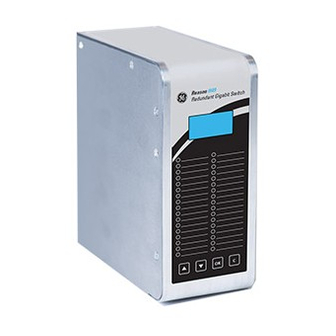
Page 16: Figure 1: Front View And Rear View
Technical Manual GE Reason H49 Chapter 4: Functional Description Hardware The following section show different views of the device together with its components. 4.1.1 Front Panel (18) (19) (20) (21) (22) (23) S1601ENb Figure 1: Front View and Rear View... - Page 17 Line 3: IP address (255.255.255.255) Line 4: Empty Navigation buttons to access and browse the device menu Reason H49 is configured through the web application user interface (detailed later in this document) or using configuration file. Signification of the LEDs...
-
Page 18: Figure 2: Reason H49 Bottom View
LED chaser and Amber 4.1.2 Bottom view Reason H49 is a 6-port switch, supporting any combination of 100Mbps and 1Gbps RJ45 copper or LC optical fiber ports. The following figure presents the bottom view of the device together with its components. - Page 19 GE Reason H49 Technical Manual Multi-mode SFP transceivers are used for connections up to 2km, and single-mode SFP transceivers can be used for distances up to 15km. Description of the slots Slot Board Description Communication port • Port 1 to port 6: SFP transceiver optical/copper...
-
Page 20: Figure 3: Example Prp Redundant Network
Technical Manual GE Reason H49 Parallel Redundancy Protocol (PRP) The Parallel Redundancy Protocol (PRP) is implemented according to the definition in the standard IEC 62439-3 (2016) Clause 4. PRP allows seamless switchover and recovery in case of network disruption (for instance cable, driver, switch or controller failure). -
Page 21: Figure 4: Reason H49 Connecting Up To Four Sans To The Prp Network
This is the case for SAN2 and SAN3. Because these SANs connect to both LANs, they can be considered as Virtual Doubly Attached Nodes and described as VDANs. Reason H49 can be configured as PRP RedBox and connect up to four SANs to the PRP network as shown in the following figure:... -
Page 22: Figure 5: Example Hsr Redundant Network
LAN. IEC 62439-3 (2016) Clause 5 assigns the term DANH (Doubly Attached Node running HSR) to such devices. Reason H49 is a DANH. The figure below shows an example of an HSR network. The doubly attached nodes... - Page 23 GE Reason H49 Technical Manual HSR is based on a ring-type architecture to achieve its network path redundancy. Duplicate packets, identified as “A” and “B”, are sent in opposite directions of the ring to achieve redundancy down to the packet level. When a packet arrives at a DANH node, the node will determine if the packet is addressed to it or to another destination.
-
Page 24: Figure 6: Two Quadboxes Linking Two Hsr Rings
Technical Manual GE Reason H49 HSR Quadbox It is possible to connect two HSR rings when the traffic flow exceeds the capabilities of a single ring. However, transmission delays from end to end are not improved. This connection is possible thanks to quadruple port devices with forwarding capabilities called QuadBoxes as shown in the following figure. - Page 25 GE Reason H49 Technical Manual Conversely, if the second QuadBox did not yet receive a copy from its interlink, it will forward the frame, but not the copy that comes later from the interlink. When a QuadBox receives a frame that it itself injected into the ring or a frame that the other QuadBox inserted into the ring, it forwards it to the interlink and to its other port if it did not already send a copy.
-
Page 26: Figure 7: Coupling Two Prp Lans To An Srs Ring
Technical Manual GE Reason H49 PRP-HSR Coupling A HSR may be coupled to a PRP network through two RedBoxes, one for each LAN as shown in the figure here below. In this case, the RedBoxes are configured to support PRP traffic on the interlink and HSR traffic on the ring ports. -
Page 27: Figure 8: Coupling An Hsr Ring To Two Prp Lans
GE Reason H49 Technical Manual The HSR RedBoxes for connecting the ring to a PRP network operate identically to those used to attach SANs, except that they are configured as RedBox “A” or RedBox “B” to accept PRP frames on their interlink. In the figure here above, RedBox A and RedBox B would send the same frame (A and AB, respectively B and BA), but if a RedBox receives the frame before it could send it itself, it refrains from sending it. -
Page 28: Figure 9: Coupling One Hsr Ring To Several Prp Networks
Technical Manual GE Reason H49 To avoid reinjecting a frame into the PRP network through the other RedBox, each HSR frame carries the identifier of the PRP network from which the frame came originally. Therefore, RedBoxes are to be configured with the NetId of the PRP network to which they are attached. -
Page 29: Figure 10: Coupling Several Hsr Rings To A Prp Network
GE Reason H49 Technical Manual Conversely, when forwarding a frame from the ring to a PRP network, a RedBox insert the LanId “A” or ”B” into the RCT, depending if it is RedBox A or RedBox B. 4.5.2 Connecting one PRP Networks to several HSR Rings... - Page 30 Technical Manual GE Reason H49 Standard Switch Reason H49 can be configured as a standard Ethernet Switch. In this case, it manages up to six Ethernet ports. Reason H49 using auto-negotiation: • Automatically determines the speed of transmission on the 10/100/1000 Base ports according to the following standards: IEEE 802.3u –...
-
Page 31: Time Synchronization
Figure 11: Example of PRP/HSR Architecture with the Precision Time Protocol (PTP) Note: On PTP protocol, a time discrepancy of 60 milliseconds per 24h is reported on Reason H49 (equipped with a SRPv3 version x) and used as Master Clock (M1) (case VDAN-P Grandmaster Clock not available). -
Page 32: Ntp Time Synchronization
4.7.2.1 Time Zone The internal clock of Reason H49 can be synchronized using NTP protocol, which sends the UTC time (Greenwich Mean Time). When using the equipment in other regions, the time zone may be set manually to correct the internal clock. -
Page 33: Snmp
The SNMP MIB consists of distinct OIDs, each of which refers to a defined collection of specific information used to manage devices over the network. GE Grid Solutions management information bases (MIB) use the following types of object identifiers (OID): •... -
Page 34: Snmp Traps
4.8.2 SNMP Traps The SNMP agent in the Reason H49 switch can send SNMP traps to the management station. Traps are change-of-state messages alerting the SNMP manager to a condition on the network. A trap message is sent to alert the management station to some event or condition on the switch such as: •... -
Page 35: Dimensions
GE Reason H49 Technical Manual Chapter 5: Installation Dimensions Figure 13: Front Face and side with dimensions H49/EN M/C22... -
Page 36: Device Labeling
Technical Manual GE Reason H49 Device Labeling The figure below shows an example of the standard labels stuck to the Reason H49 switch: Manufacturer Label Firmware Label Manufacturing Label S1616ENa Figure 14: Example of Device Labeling Main information present in these labels includes: •... -
Page 37: Manufacturing Label
GE Reason H49 Technical Manual 5.2.1 Manufacturing Label Figure 15: Manufacturing Label Label1 - Manufacturing Label Label 20x94mm Diagram number: GP0067001_B Reference of the product: GP0067001 Version of the product: B Serial number: 11111158/06/16 Unique serial number: 8 numerical digits: 11111158... -
Page 38: Firmware Label
Technical Manual GE Reason H49 5.2.2 Firmware Label Figure 16: Firmware Label Label2 - Firmware Label Label 10x27mm Firmware version: H49_2.0.0.0 Name of the product: H49 First digit: Major functional version (2) Second digit: Compatibility indicator version (0) Third digit: Maintenance/Evolution/Bug fix version (0) -
Page 39: Mounting
Technical Manual Mounting Reason H49 is designed to be mounted vertically on a standard DIN Rail. For this purpose, two adjustable mounting brackets are located on the back of the H49, one at the top and one at the bottom of the rear face as shown below:... -
Page 40: Recommendations For Electromagnetic Compatibility
A closer spacing will result in higher device operating temperature. Caution: The orientation in which the Reason H49 is fitted on the DIN Rail is a key factor to optimal performance. Reason H49 requires to be installed vertically on the DIN rail. Other position would lead to inadequate ventilation and result in increased heat generation. -
Page 41: General Wiring
GE Reason H49 Technical Manual Chapter 6: Connection As well as connections to the Ethernet network, Reason H49 requires auxiliary power supply connection and safety earth connection. Alarm outputs are provided and these should be connected for system supervision. The locations of the various connection points are detailed section Bottom view. -
Page 42: Earth Wiring
Technical Manual GE Reason H49 Earth Wiring 6.2.1 Protective Earth Wiring This equipment requires a protective conductor (earth) to ensure user safety according to the definition in the standard IEC 60255-27: 2005 Insulation Class 1. Warning: – To preserve the device's safety features, the protective conductor (earth) MUST not BE disturbed when connecting or disconnecting functional earth conductors, such as cable screens, to the PCT stud. -
Page 43: Casing / Earth Interconnection
To protect against disturbances, each Reason H49 must be carefully and correctly interconnected. Within Reason H49 equipment, earth and casing must be connected to a grid-like grounding system in the shortest possible way using low impedance (at high frequencies), wide and short electrical connections (wires or braids) as specified in the IEC 61000-5 standard. -
Page 44: Figure 23: Reason H49 Power Supply Wiring
Technical Manual GE Reason H49 Power Supply Wiring Reason H49 contains a Basic Interface Unit (BIU261D) board, which includes two redundant power supply inputs, as shown in the following figure: Figure 23: Reason H49 Power Supply Wiring BIU261D primary power supply... -
Page 45: Figure 25: Typical 2-Way Female Connector
GE Reason H49 Technical Manual BIU261D primary power supply Pin n° Description 1 to 21 Not used Voltage input: GND Voltage input: AC/DC ( + ) Voltage input: AC/DC ( - ) Note: Inputs must be connected to the specified pins. Other pins must remain unused and no other connection has to be made. - Page 46 It will continue to use the primary power supply source as long as it is available, even when the secondary power supply becomes available again. Reason H49 supports the following power supply use cases: Primary source Secondary source...
-
Page 47: Figure 26: Relay Alarm Wiring
GE Reason H49 Technical Manual Alarm Relay Wiring The 3-pin connector of the relay alarm on the SRPV3 board allows the following H49 statuses: S1351ENa Figure 26: Relay Alarm Wiring Signal Description Closed=Normal Operation Open= Power supply defect (both input voltage sources are... -
Page 48: Figure 28: Pluggable Terminal Block
Technical Manual GE Reason H49 6.4.1.2 Crimped Ferrule For safety reasons, wire terminations must be insulated using an insulated crimped ferrule, suitable for 2,5mm wire size. Figure 28: Pluggable Terminal Block Insulated wire ferrules must be slipped over the stripped cable and crimped to prevent stranded wire from fraying. -
Page 49: Figure 29: Sfp Module Connection
Technical Manual Ethernet Connections Reason H49 is easy to install and operate. It is designed to work in an electrical plant environment and it is fully certified IEEE 1613 series, IEC 61850-3 and IEC 60255-27. Reason H49 connects to the network through a Small Form-factor Pluggable module... - Page 50 Reference Manufacturer Description Image Type ABCU-5741ARZ fit-foxconn 10/100/1000Mbps RJ45 Caution: Reason H49 is delivered with SFP cap inserted in each SFP cage. The cap must be inserted in each SFP cage unused. It is a protection against dust. H49/EN M/C22...
-
Page 51: Figure 30: Rj45 Sfp Module
Technical Manual 6.5.1 RJ45-Type Connection The following figure shows the RJ45-type module used by the Reason H49 switch and its corresponding RJ45 connector. Insulated cable category 6 or 5e (FTP: Foil Twisted Pair) or insulated (STP – Shielded Twisted Pair) with RJ45 connectors are mandatory. -
Page 52: Figure 31: Ethernet Fiber Optic - Lc-Type Module
Technical Manual GE Reason H49 6.5.2 Optical LC-type Connections The following figure shows the optical LC-type module used by the Reason H49 switch and its corresponding LC-type connector. S1354ENa Figure 31: Ethernet Fiber Optic – LC-type Module Warning about Laser Rays Caution: NEVER look into optical fibers. -
Page 53: Figure 33: Fiber Budget
GE Reason H49 Technical Manual Fiber Optic Budget Calculations Optical power is expressed in Watts. However, the common unit of power measurement is the dBm, defined by the following equation: Power (dBm) = 10 log Power (mW) / 1 mW. -
Page 54: Power Up
Technical Manual GE Reason H49 Power up During the power up process the following indicators are displayed: • LED 1 is green • LED 2 is amber • LED 18 indicates the state of the redundant power supply At the end of the power-up process, the following indicators are displayed: •... -
Page 55: Connecting To Reason H49
CLI (command Line Interface) can be used to read/write most settings (SSH). Note: This chapter only explains how to configure the Reason H49 switch through the embedded web server. However, an appendix, at the end of this document, describes the command lines supported by the SSH service. - Page 56 Technical Manual GE Reason H49 Browser name Manufacturer Chrome Google Internet Explorer Microsoft Mozilla Foundation Mozilla Firefox Mozilla Corporation Safari Apple Inc. 2 In the web browser’s address bar, type the default H49’s IP address: 192.168.254.254 and press Enter on your keyboard.
-
Page 57: Figure 34: Reason H49 Web User Interface - Error During Login Process
Figure 34: Reason H49 Web User Interface - Error during Login Process When connecting to Reason H49 for the first time, the system prompts the user to change the default password. •... -
Page 58: Figure 36: Reason H49 Web User Interface - Start Page
System Network Security • A setting panel, on the right. Navigate through the configuration menu to access each of the switch’s functions. Figure 36: Reason H49 Web User Interface – Start Page H49/EN M/C22... -
Page 59: Figure 37: H49 Web User Interface - Power Supply Status
It also allows the user to update the main system attributes. 7.4.1.1 Status To get the global status of the Reason H49 switch, click Status in the System section: The top part of the page shows the following information: Attribute... -
Page 60: Figure 38: H49 Web User Interface - Interfaces Status
Technical Manual GE Reason H49 Interfaces This area displays the interface status: Figure 38: H49 Web User Interface – Interfaces Status Note: The interface configuration is done in the System > Redundancy Mode page. Each interface has a colored button and some details:... -
Page 61: Figure 39: H49 Web User Interface - Statistics Of A Connected Interface
Time Synchronization This area displays read-only information about the device’s time synchronization protocol. Figure 40: Reason H49 Web User Interface – Time Synchronization Status This information comes from the configuration done in the System > Global Settings page. The following attributes are also displayed according to the selected value. - Page 62 Technical Manual GE Reason H49 NTP attributes Attribute Description System's time synchronization mode: • Disable • Client Mode • Client/Server • Server Time synchronization status: • Synchronized Status • Not synchronized PTP attributes Attribute Description Synchronization mode of the system: •...
-
Page 63: Figure 41: Reason H49 Web User Interface - Logs Status
This area displays the log messages in a Syslog format. The syslog level is divided in 4 categories: error, warning, notice and information: Figure 41: Reason H49 Web User Interface – Logs Status The following table gives a description of each table columns:... -
Page 64: Figure 42: Reason H49 Web User Interface - Logs Status
Technical Manual GE Reason H49 7.4.1.2 Global Settings To configure the global settings of the Reason H49 switch, click Global Settings in the System section. Figure 42: Reason H49 Web User Interface – Logs Status H49/EN M/C22... - Page 65 GE Reason H49 Technical Manual Network The Network area allows the user to modify the usual TCP/IP network parameters. An explanation of each configuration item is given in the following table: Attribute Description Factory Default Name Name of the system Undefined Default VLAN ID.
-
Page 66: Figure 43: Reason H49 Web User Interface - Ptp Settings
Technical Manual GE Reason H49 PTP Configuration Figure 43: Reason H49 Web User Interface – PTP Settings Set the PTP settings as detailed below: Attribute Description Factory Default Use the drop-down list to select the PTP switching mode: • Disable... -
Page 67: Redundancy Mode
To set up the H49 redundancy mode, click System > Redundancy Mode. Click the desired redundancy mode among the preset switch configurations: Selected Redundancy Mode Description Uses Reason H49 as a standard switch. None All the ports are enabled by default. Ports 1 and 2 are reserved for redundant connection to LAN A and LAN B respectively. -
Page 68: Figure 44: Reason H49 Web User Interface - No Redundancy Mode Selected
In order to facilitate identification, each port is colored in relation to its configured function: Color Description Redundant port Green Redundant port Blue HSR/PRP coupling port White Standard port Grey OFF port Figure 44: Reason H49 Web User Interface – No Redundancy Mode Selected H49/EN M/C22... -
Page 69: Figure 45: Reason H49 Web User Interface - Prp Redbox Mode Selected
Note: When switching from one redundancy mode to another, reboot Reason H49 to apply changes in the Start-up configuration. The system and network configuration will be erased except the Name; IP address; Subnet mask and Gateway attributes set in the Global Settings >... -
Page 70: Figure 46: Reason H49 Web User Interface - Snmp Page
GE Reason H49 7.4.1.4 SNMP Reason H49 implements Simple Network Management Protocol (SNMP) and is capable of exchanging information with other SNMP devices on the network. This information is saved in the Management Information Base (MIB) of the switch. To configure the SNMP settings of the switch, click System > SNMP: Figure 46: Reason H49 Web User Interface –... -
Page 71: Figure 47: Reason H49 Web User Interface - Snmp Version Section
Click the remove button in front of the desired row, to delete an element from a section. SNMP Version selection From the SNMP mode drop-down list, select the desired SNMP protocol version to be used to manage the switch: Figure 47: Reason H49 Web User Interface – SNMP Version Section H49/EN M/C22... -
Page 72: Figure 48: Reason H49 Web User Interface - Snmp Community Section
Authentication key to access the device (acts as a password) Groups Manage user groups by defining the group name and the related community name: Figure 49: Reason H49 Web User Interface – SNMP Group Section for SNMP v1/v2c Attribute Description... -
Page 73: Figure 50: Reason H49 Web User Interface - Snmp User Section For Snmp V3
SNMP v3 Users This section allows the user to manage SNMP users: Figure 50: Reason H49 Web User Interface – SNMP User Section for SNMP v3 Set the SNMP users together with their authentication and their privacy attributes as detailed below:... -
Page 74: Figure 51: Reason H49 Web User Interface - Snmp Group Section For Snmp V3
GE Reason H49 Groups Manage user groups by defining the group name and the user that belongs to this group: Figure 51: Reason H49 Web User Interface – SNMP Group Section for SNMP v3 Attribute Description Group name A unique group name... -
Page 75: Figure 53: Reason H49 Web User Interface - Snmp Access Configuration Section
You shall be careful not gathering two contradictory view in the same group; for example: gathering a View including a given OID and another view excluding the same OID. Figure 53: Reason H49 Web User Interface – SNMP Access Configuration Section Attribute Description... -
Page 76: Figure 54: Reason H49 Web User Interface - Device Management
Figure 54: Reason H49 Web User Interface – Device Management Firmware Update The Firmware section allows an authorized user to keep Reason H49 up to date with the latest firmware from General Electric or revert the switch to factory settings and firmware. -
Page 77: Figure 55: Reason H49 Web User Interface - Select A Firmware File
To update firmware, go to the System > Management menu. • Click the “…” button and then, select the correct .tar.gz file: Figure 55: Reason H49 Web User Interface – Select a Firmware File • Click the “Upgrade Firmware” button to activate the upgrade process: Figure 56: Reason H49 Web User Interface –... -
Page 78: Figure 58: Reason H49 Web User Interface - Select The Configuration File To Be Imported
Click the “…” button to navigate to the folder that contains the configuration file and then, select the relevant .yaml, yml file: Figure 58: Reason H49 Web User Interface – Select the Configuration File to be imported • Click “Change Running” to import the file. -
Page 79: Figure 60: Reason H49 Web User Interface - New Configuration Notification
It is possible to export the Running and/or the Startup configurations of the switch (.yaml file). • Click the corresponding button as shown in the following figure: Figure 62: Reason H49 Web User Interface – Downloading Running or Startup Configuration H49/EN M/C22... -
Page 80: Figure 63: Reason H49 Web User Interface - Configuration Export
From the popup that appears on screen, select Save File and click OK to save it to the local host: Figure 63: Reason H49 Web User Interface – Configuration Export By default, the file is saved to the Downloads folder onto your local host. -
Page 81: Figure 66: Reason H49 Web User Interface - Interface Configuration
GE Reason H49 Technical Manual 7.4.2 Network This section provides the current network configuration of the Reason H49 switch. 7.4.2.1 Interface This page allows the user to configure the device’s interfaces available in the selected redundancy mode. Each interface is represented by a row in the table. - Page 82 Enable Check the box to enable a port. Reason H49 interfaces can be configured either as access ports or a trunk ports, as follows: • Access: An access port can have only one VLAN configured on the interface; it can carry...
-
Page 83: Figure 67: Reason H49 - Location Of M6 Screws To Be Removed
Reason H49 to default factory configuration by replacing the raw image stored at switch’s memory. When factory reset is required, the first step to be done is requiring GE for the raw file of the switch (h49-x.x.x.x-buildxx-xx.tar.gz file). After this file is received: •... -
Page 84: Figure 68: Reason H49 - Location Of The Micro Sd Card
GE Reason H49 • Remove the micro SD card from the SRPV3 board: Figure 68: Reason H49 – Location of the Micro SD Card • Insert the micro SD card into your Windows PC’s card reader. You may use an SD card adapter to fit into the SD card slot. -
Page 85: Figure 70: Win32Diskimage Program - Select The Raw Image Of The Switch
GE Reason H49 Technical Manual • Click the folder icon to open the file explorer. Set the Files of type to *.* and then, select the unzipped raw file. Click Open. Figure 70: Win32DiskImage Program – Select the Raw Image of the Switch •... -
Page 86: Figure 73: Win32Diskimage Program - Overwrite Process In Progress
Technical Manual GE Reason H49 • The raw file is being copied on the SD card: Figure 73: Win32DiskImage Program – Overwrite process in progress • Once the process is complete, click OK: Figure 74: Win32DiskImage Program – Overwrite process done successfully •... - Page 87 GE Reason H49 Technical Manual 7.4.2.1.2 Insulation Resistance and Earth Continuity Checks If the unit is disassembled to access the internal Micro SD card, then the following checks must be made after the unit is reassembled and before use. Caution:...
- Page 88 Technical Manual GE Reason H49 Earth Continuity Check • Using a continuity tester or Digital Multimeter, check that the resistance from the PCT to all other conductive case components on the unit is <1Ω. • If any of the test measurements are not <1Ω then the root cause must be identified and rectified before the unit can be returned to active service.
-
Page 89: Figure 75: Reason H49 Web User Interface - Vlan Configuration
To configure virtual LANs in Reason H49, click Network > VLAN. Figure 75: Reason H49 Web User Interface – VLAN Configuration Reason H49 can manage up to 4096 configurable Virtual LANs. Each VLAN (starting from 2) can handle up to six VLAN ports. -
Page 90: Multicast Filtering
Technical Manual GE Reason H49 Set the Virtual LAN attributes, as described below: Attribute Description For tag-based VLANs, this is the ID to look for in the tag. It identifies the individual VLANs you create on your network. The VLAN ID must be specified in the range from 1 to 4094. -
Page 91: Figure 76: Multicast Filtering Principles
Multicast 1 Host S1620ENa Figure 76: Multicast Filtering Principles Reason H49 supports adding MAC addresses manually to restrict or filter multicast traffic automatically. The filter relies on a range of MAC addresses applied to one or more device ports (interfaces). -
Page 92: Figure 78: Reason H49 Web User Interface - Priority Configuration
Reason H49 provides a mechanism for priorizing Ethernet frames by using Priority Code Points. Four priority queues (from 0 to 3) are present in Reason H49 (3 being the highest priority) and eight Priority Code Point (PCP) can be distributed among the queues. -
Page 93: Figure 79: Reason H49 Web User Interface - Security Configuration
To configure security settings, click Security > Security Settings. From this page, you can set the user and system management parameters and manage TLS and trusted certificates. Figure 79: Reason H49 Web User Interface – Security Configuration System Set the system security settings as described below:... -
Page 94: Figure 80: Reason H49 Web User Interface - Certificate Management
Certificates are used in a network to provide secure access. This is an electronic document that identifies an entity (machine, server or other) and associates that entity with a key. Reason H49 uses certificates for communicating with external servers such as the syslog and LDAP server or upgrading HTTPS. Caution: To manage system certificates from the Security Settings page, you must be a Security Administrator. -
Page 95: Figure 81: Reason H49 Web User Interface - Local User Account Configuration
To configure local user accounts and local user account policy, click Security > User Accounts. Figure 81: Reason H49 Web User Interface – Local User Account Configuration Note: This page allows the user to create, edit and remove local user accounts. These user accounts are used only if no LDAP account management has been defined or if the LDAP server is not accessible. - Page 96 Technical Manual GE Reason H49 Attribute Description Number of consecutive login attempts before locking a user account. • 0 means that this policy is disabled. Consecutive Login Attempts • The maximum number of attempts is 10. Set the locking period of the user accounts.
- Page 97 • To create a new local user account, click New: Figure 93: Reason H49 Web User Interface – Create Local User Account In the Account Settings popup, complete the following attributes: Attribute...
- Page 98 Figure 94: Reason H49 Web User Interface – Edit a Local User Account In the Account Settings popup, make the relevant changes: Figure 95: Reason H49 Web User Interface – Change Settings of a Local User Account If the selected user’s account is locked, an unlock button is available for users with Security administrator role.
-
Page 99: Figure 82: Reason H49 Web User Interface - User Account Settings Icon
Users can update their own account settings. These attributes are accessible by clicking on the user icon in the top-right corner of the web server application: Figure 82: Reason H49 Web User Interface – User Account Settings Icon The attributes displayed in the Account Settings window are: •... -
Page 100: Figure 84: Reason H49 Web User Interface - Ldap Server Settings
This page allows configuring the LDAP server for remote authentication. The information in this page is used when the LDPA authentication mode is selected in the Security > Security Settings page (see Security Settings section). Figure 84: Reason H49 Web User Interface – LDAP Server Settings Attribute Description LDAP Server IP address LDAP Server’s IP address (for instance 10.17.10.10) -
Page 101: Syslog Server
GE Reason H49 Technical Manual In any case, the Reason H49 switch cannot edit the passwords associated to LDAP- managed accounts. Note: If the LDAP server is temporarily unreachable, you may experience access issues to user management features (User Account creation...) from the H49. -
Page 102: Figure 85: Reason H49 Web User Interface - Syslog Server Settings
When TCP or TCP/TLS is used: • If the log server is unavailable, the log messages are temporarily buffered and they are sent to the server upon service reestablishment. Figure 85: Reason H49 Web User Interface – Syslog Server Settings H49/EN M/C22... -
Page 103: Reason H49 Cyber Security Implementation
Various standards and recommendations apply to substation cyber security and consist in maintaining the Availability, Integrity and Confidentiality of the substation data and automation processes. Reason H49 Cyber Security Implementation At the Reason H49 level, the following cyber security measures have been implemented: • Encryption and Credential •... -
Page 104: Secured File Transfer
8.1.3.1 Role-Based Access Reason H49 uses the concept of Roles and Rights. This process consists in assigning local authorized users to one predefined roles and is known as Role-Based-Access Control (RBAC). - Page 105 GE Reason H49 Technical Manual Attribute Description The "Security Administrator" is responsible of the Security policy. He/she is ONLY allowed to reset passwords, define the security parameters, and visualize the security logs. Security Administrator The "Security Administrator" is not allowed to display any data of DS Agile system, load a database nor change a sub-system operating mode.
-
Page 106: Figure 86: Network Architecture With Centralized Authentication
User authentication is a process that verifies the identity of a user who connects to a device. Any user interaction with Reason H49 requires authentication through a login and password, whatever the interaction service (protocol) and regardless of the interaction type (read, write). -
Page 107: Local Authentication
Security > User Accounts page. Default User By default, Reason H49 is delivered with a default administrator account. When connecting to Reason H49 for the very first time via the web server, the user shall use the following default authentication information: •... -
Page 108: Password Management
Password Management One of the fundamental principles of cyber security consists in combining a user ID with a password. For Reason H49, password policy is implemented in compliance with IEEE 1686 recommendations. Password Complexity The password policy is implemented for all local users. -
Page 109: Figure 87: Reason H49 Web User Interface - User Account Settings Icon
Users can update their own account settings by clicking on the user icon, in the top- right corner of the web application: Figure 87: Reason H49 Web User Interface – User Account Settings Icon The following attributes can be modified: •... -
Page 110: Remote Logs
Sensitive information such as passwords is not logged. 8.1.8 Remote Logs Reason H49 supports logging to a remote Syslog server. Refer to the Security Settings section for more details At any time, the security administrator can enable/disable logging to a central syslog server. -
Page 111: Other Security Measures
Hardening is the process of securing a system by reducing its surface of vulnerability. This includes the removal of unnecessary software, unnecessary usernames or logins and the disabling or removal of unnecessary services. By default, Reason H49 configuration is hardened according to CIS (Center for Internet Security) recommendations. Disabling Ports The availability of unused ports could provide a security risk. -
Page 112: Maintenance Period
Caution: Before carrying out any work on this product you should study the contents of the safety and technical data of the GE Grid Solutions Safety Guide SFTY/4L M/H11 (or later issue) and the ratings on the equipment rating label. -
Page 113: Firmware Upgrade
Most of the faults are indicated through the LEDs in the front panel. See the Hardware section for more details on LEDs indication. Reason H49 supports monitoring access through SNMP. It is the responsibility of the maintenance procedure to regularly monitor the device in order to verify it healthy functioning. -
Page 114: Testing The Leds
Technical Manual GE Reason H49 Testing the LEDs Reason H49 provides a mechanism allowing us to test the correct functioning of the LEDs present in the front panel. • Press "OK" + "C" buttons: all LEDs turn RED, • Message "LED test / press OK" is displayed on the LCD •... -
Page 115: Repair And Modification Procedure
GE Reason H49 Technical Manual 9.6.1.2 Installing a replacement product To reinstall a replacement product: 1 Attach the product to the DIN rail 2 Connect the protective earth connection 3 Connect the power supply connection(s) 4 Establish an HTTPS connection and set the IP Address, etc. - Page 116 Technical Manual GE Reason H49 5 Send the product to the repair centre: Address the shipment to the repair centre specified by your local contact Make sure all items are packaged in an anti-static bag and foam protection ...
-
Page 117: Environmental Conditions
Note 3: According to IEC 60255-21 series Note 4: These conditions correspond to maximum values given for classes 3C1 and 3S1 in IEC 60721-3-3. Note 5: The ambient air temperature is the maximum or minimum temperature around the enclosure of Reason H49 H49/EN M/C22... -
Page 118: Electromagnetic Compatibility
60s, Test voltage < 12Vdc or IEC 60255-27:2013 Mechanical ports resistance 12 Vrms ac 10.3.2 Electromagnetic Compatibility 10.3.2.1 Standard compliance Reason H49 is compliant with European Commission Directive on EMC (IEC 61000-5 standard). 10.3.2.2 DC Auxiliary supply Description Test Standard Group Test Level IEC 61000-4-29:2000... - Page 119 GE Reason H49 Technical Manual 10.3.2.3 AC Auxiliary Supply Description Test Standard Group Test Level IEC 61000-4-11:2004 Supply Interruptions AC voltage interruptions AC Power ports ΔU 100% for 5 periods, 50 periods IEC 60255-26:2013 ΔU 30% for 1 period IEC 61000-4-11:2004...
- Page 120 Technical Manual GE Reason H49 Description Test Standard Group Test Level 0,15 MHz to 0,5 MHz: μV) to 87 dB(μ V) quasi 97 dB( -peak μV) to 74 dB(μ V) aver 84 dB( 53 dB( μA) t o 43 dB( μA) quasi...
- Page 121 GE Reason H49 Technical Manual Description Test Standard Mode Group Test Level Level 4 : 30V/m (rms) Frequency sweep: IEC 61000-4-3:2010 6 Faces Enclosure ports from 800MHz to 960MHz from 1400MHz to 2000MHz Level 4: IEC 61000-4-2:2008 Electrostatic Discharge Enclosure ports 15kV air discharge.
- Page 122 Technical Manual GE Reason H49 Level 4: 30 Vrms cont. 300 Vrms for 1 s IEC 61000-4-16- DC Power port, compil:2011 Coupling resistor 200Ω and Main frequency voltage Signal ports coupling capacitor 1uF - DC and IEC 60255-26:2013 inputs Coupling resistor 50Ω -...
-
Page 123: Safety Tests
GE Reason H49 Technical Manual 10.3.3 Safety tests Description Test Standard Test Level IEC 62439-1:2010 IEC 62439-3:2016 IEC 61850-8-1:2011 Functional performance requirements PRP, HSR and PTP functional features IEC 61850-90-4:2013 IEC 61850-9-3:2016 IEC 61588:2009 Pollution degree= 2 Clearance and creepage distances... - Page 124 Technical Manual GE Reason H49 Description Test Standard Test Level Test Db: +25 °C ± 3 °C - 97 % –2 %+3 % RH Damp heat cyclic (12 h+12 h) IEC 60068-2-30:2005 +55 °C ± 2 °C - 93 % ± 3 % RH 6 of 24 hours (12 h + 12 h) cycles 10.3.4.3...
-
Page 125: Ieee1613 Certification
GE Reason H49 Technical Manual 10.4 IEEE1613 Certification Description Test Standard Mode Group Test Level Service conditions IEEE C37.90:2007 - B8 Device Installation Zone A Operating temperature: -25°C to Operational temperature range IEEE C37.90:2007 - B8 Device 55°C Storage temperature: -40°C to 70°C... - Page 126 Technical Manual GE Reason H49 Power, Input/output, 2,5kV crest value (tolerance IEEE C37.90:2007 - B8 Data com and signal +0/–10%.) Surge withstand capability ports (SWC) 2,5kV crest value (tolerance IEEE C37.90:2007 - B8 Power and output ports +0/–10%.) Level 4: Source impedance 2Ω, Line-to-...
- Page 127 GE Reason H49 Technical Manual a) Contact discharge (direct/indirect) = 8 kV Electrostatic discharge tests IEEE Std C37.90.3:2012 - B4 Enclosure port b) Air discharge (direct) = 15 kV Immunity to conducted DC and AC Power ports, disturbances induced by RF...
-
Page 128: Auxiliary Fault Relays (Optical Port Alarm)
Technical Manual GE Reason H49 10.5 General Characteristics Item Description Rated Insulation Voltage 300V Pollution degree Overvoltage category 10.5.1 Mechanical Item Description Dimensions W x H x D = 165 mm x 176 mm x 75 mm Weight 1.3 kg... -
Page 129: Biu261D
GE Reason H49 Technical Manual 10.5.4 BIU261D 10.5.4.1 Maximum measured burden in Volt-ampere (VA) Item Power supply voltage Maximum burden AC powered on main power supply 110 Vac 23.19 Maximum burden DC powered on main power supply 110 Vdc 16,16... -
Page 130: Manufacturer
Technical Manual GE Reason H49 10.7 Manufacturer General Electric Grid Solutions Worldwide Contact Centre St Leonards Building, Red Hill Business Park, Stafford ST16 1WT, United Kingdom, UK Tel: +44 (0) 1785 25 00 70 Fax: +44 (0) 1785 27 09 40 www.gegridsolutions.com/contact/... -
Page 131: Chapter 11: Glossary
GE Reason H49 Technical Manual Chapter 11: Glossary 100 Base-FX The fiber optic ports are full duplex at 100 Mbps only. The copper ports are full/half duplex and auto-sense the transmission speed. They will auto- 10Base-T; 100Base-T and negotiate with the connected device to determine the optimal speed. When the connected 1000Base-T device is only capable of transmitting at 10 Mbps, the switch makes a 10 Mbps connection. - Page 132 Technical Manual GE Reason H49 100 Base-FX The fiber optic ports are full duplex at 100 Mbps only. Network Time Protocol. The OSI physical layer: The physical layer provides for transmission of cells over a physical medium. Power management If there is no cable on a port, most of the circuitry for that port is disabled to save power.
-
Page 133: Appendix 1 Configuring Reason H49 From Command Lines
Select Use the following IP address and type a compatible IP address and a sub mask of 255.255.0.0 Click OK to save the change. Reboot your PC if prompted. Connect an Ethernet cable between your PC and any port on the Reason H49 switch. Note: The device connects to the network through a Small Form-factor Pluggable module (SFP). -
Page 134: Figure 88: Ssh Console - Establish The Connection With The H49
Technical Manual GE Reason H49 1 Start the PuTTY console 2 Click the Session menu from the tree-view on the left-side of the window 3 In the Host Name (or IP address) entry field, type the IP address of the switch 192.168.254.254... -
Page 135: Login To The H49
If an error occurs during the authentication process, an information message appears on screen, as shown in the following figure. Figure 90: SSH Console – Error during the Login Process When connecting to Reason H49 for the first time, the system prompts the user to change the default password. •... -
Page 136: Figure 92: Ssh Console - Agreement Conditions
GE Reason H49 Read the License agreement and type Y (for yes) to agree to the terms: Figure 92: SSH Console – Agreement Conditions The Reason H49’s start screen appears: Figure 93: SSH Console – H49 Main Menu Note: To modify the appearance of the SSH console, select Appearance under the Window menu and change the desired formatting options, or go to Colours to change the use of Foreground and Background colours. -
Page 137: Cli Commands
GE Reason H49 Technical Manual 12.1.4 CLI Commands This section gathers the list of command lines that can be used to configure the Reason H49 switch. A command line is a combination of a command name, a parameter name and a... - Page 138 Sets Gateway IP address 0.0.0.0 Sets DNS Server IP Address 10.18.0.134 Sets synchronization time local, ntp, ptp The following values can be set the Time zone of the Reason H49: command parameter Description Values Sets the time zone timezone...
- Page 139 Sets VLAN used for PTP 0 to 4094 Sets PCP used for PTP 0 to 7 Sets the PTP synchronization to slave mode. Redundancy Mode The following values can be set to configure the Reason H49 Redundancy function: command parameter Description Values HSR-PRP-A,...
- Page 140 Technical Manual GE Reason H49 SNMP SNMP is configured by manually editing the file /etc/snmp/snmpd.conf command parameter Description Values Sets the single-quoted ‘configuration_line’ string into the configuration. The See “Supported associated line is either added or modified if already existing.
- Page 141 GE Reason H49 Technical Manual • group • includeAllDisks • iquerySecName • load • monitor • proc • rocommunity • rouser • rwcommunity • rwuser • sysContact • sysLocation • sysName • sysServices • trap2sink • trapsink • view Note: Unsupported settings are passed directly to the SNMP configuration without further checking.
-
Page 142: Network Commands
Saves the settings in the startup configuration (running to startup) Sets the network-related settings to the factory default The following values can be set to update the firmware of Reason H49 or change the general configuration for the redundancy mode:... - Page 143 GE Reason H49 Technical Manual Interface The following values can be set to configure the Reason H49 interfaces. interface <ifname> [-D] [-d] [-h] [-i] [-v] [-y] command parameter Description Values Interface name CE01 to CE06 ifname Sets interface state Enable, disable...
-
Page 144: Mac Address Table
Sets the Aging Base Time i.e how long MAC addresses remain in the Ethernet switching table. Reason H49 uses a mechanism called aging to store MAC addresses in the Ethernet switching table (the MAC table). When the aging time for a MAC address in the table expires, the address is removed. - Page 145 GE Reason H49 Technical Manual 12.1.4.3.2 Filtering The following values can be set to configure filtering and redirection policy. This command is also used to create rules to perform specific actions on specific Mac addresses. filtering <interface> -e <entry> -s <state> -a <MAC address>...
- Page 146 Technical Manual GE Reason H49 12.1.4.4 Security Commands Security Settings The following values can be set in the Security configuration to setup security options about user session and user password policy. security [-d] [-h] [-v] [-I <minutes>] [-l <minutes>] [-a <nb_max_attempts>] [-P] [-L <length>] [-i] [-f]...
- Page 147 GE Reason H49 Technical Manual LDAP Server The following values can be set in the LDAP configuration to use Central Authentication: command parameter Description Values Sets the LDAP server’s address or FQDN Sets the TCP/IP port Sets the base dn of LDAP Server...
- Page 148 Technical Manual GE Reason H49 Banner Text The following values can be set to configure the login banner text to be displayed at user log on: command parameter Description Values IP address of the remote FTP/SFTP server Enables the debug mode...
-
Page 149: Appendix 2 Command Line Use Cases
The example below shows the use of the redundany command line: Command Description Sets the Reason H49 redundancy mode, the network ID and the redundany -l -n -a redundancy supervision MAC address Example: redundancy –l HSR-PRP-A –n 2 –a 01:15:4E:00:01:00 12.2.1.2... -
Page 150: Alarm Contact
Technical Manual GE Reason H49 12.2.1.3 Switch The example below shows the use of the switch command line: Command Description Sets the switching mode switch -m Example: switch –m adaptative 12.2.1.4 Alarm Contact The example below shows the use of the... -
Page 151: Networks Commands
GE Reason H49 Technical Manual 12.2.2 Networks Commands 12.2.2.1 Interface The example below shows the use of the interface command line: Command Description Shows the interface status, VLAN settings Interface -i Example: H49/EN M/C22... - Page 152 Technical Manual GE Reason H49 12.2.2.2 VLAN The example below shows the use of the vlan command line: Command Description Sets the name of the VLAN, its ID and the ports to be added vlan -c -l -p Example: vlan –c test –l 5 –s test –p CE01:CE02:CE03:CE04:CE05 12.2.2.3...
- Page 153 GE Reason H49 Technical Manual 12.2.2.5 The example below shows the use of the ptp command line: Command Description Sets the IEEE1588-v2 PTP configuration i.e. the operating mode, delay, ptp -m -l -f -p1 -p2 -a -s -c -n profile, domain, and step together with the IEEE1588-v2 prority1 and 2, the priority code point (PCP) of the PTP frames and the VLAN used.
-
Page 154: Security Commands
Technical Manual GE Reason H49 12.2.3 Security Commands 12.2.3.1 Account The examples below show the use of the account command line: Information Example of command Description Displays information about account configuration account -i Example: Figure 94: SSH Console – Information about the account configuration... - Page 155 GE Reason H49 Technical Manual 12.2.3.2 LDAP The examples below show the use of the ldap command line: Configure LDAP Server Example of command Description Sets the LDAP server address with an FQDN, an IP address ldap -a <FQDN>,<IP_address> -p and the port of connection <Port_number>...
-
Page 156: Figure 95: Ssh Console - Information About The Security Configuration
Technical Manual GE Reason H49 12.2.3.3 Security security command line: The examples below show the use of the Information Example of command Description Displays information about security configuration security -i Example: Figure 95: SSH Console – Information about the security configuration... - Page 158 GE Grid Solutions Parc Eurêka, 81 rue Euclide, CS11140 34060 Montpellier Cedex 2, France Worldwide Contact Center Web: www.GEGridSolutions.com/contact Phone: +44 (0) 1785 250 070 www.gegridsolutions.com/contact © 2017 General Electric. All rights reserved. Information contained in this document is indicative only.
Need help?
Do you have a question about the Reason H49 and is the answer not in the manual?
Questions and answers