
Related Manuals for 3Com 3C10111C - NBX 100 - Modular Exp Base


Summary of Contents for 3Com 3C10111C - NBX 100 - Modular Exp Base
- Page 1 ® Installation Guide Release 4.3 SuperStack 3 NBX ■ NBX 100 ■ http://www.3com.com/ Part No. 900-0155-01 Published June 2004...
- Page 2 3Com Corporation reserves the right to revise this documentation and to make changes in content from time 01752-3064 to time without obligation on the part of 3Com Corporation to provide notification of such revision or change. 3Com Corporation provides this documentation without warranty, term, or condition of any kind, either implied or expressed, including, but not limited to, the implied warranties, terms, or conditions of merchantability, satisfactory quality, and fitness for a particular purpose.
- Page 3 _________________________________________________________________________________ libtar 2.1.11 Copyright © 1998-2003 University of Illinois Board of Trustees Copyright © 1998-2003 Mark D. Roth All rights reserved. Developed by: Campus Information Technologies and Educational Services, University of Illinois at Urbana-Champaign Permission is hereby granted, free of charge, to any person obtaining a copy of this software and associated documentation files (the “Software”), to deal with the Software without restriction, including without limitation the rights to use, copy, modify, merge, publish, distribute, sublicense, and/or sell copies of the Software, and to permit persons to whom the Software is furnished to do so, subject to the following...
- Page 4 2. Redistributions in binary form must reproduce the above copyright notice, this list of conditions and the following disclaimer in the documentation and/or other materials provided with the distribution. 3. All advertising materials mentioning features or use of this software must display the following acknowledgement: This product includes software developed by the University of California, Berkeley and its contributors.
- Page 5 _________________________________________________________________________________ OpenBSD: strdup.c,v 1.3 1997/08/20 04:18:52 millert Exp Copyright © 1988, 1993 The Regents of the University of California. All rights reserved. Redistribution and use in source and binary forms, with or without modification, are permitted provided that the following conditions are met: 1.
- Page 6 _________________________________________________________________________________ strmode.c Copyright © 1990 The Regents of the University of California. All rights reserved. Redistribution and use in source and binary forms, with or without modification, are permitted provided that the following conditions are met: 1. Redistributions of source code must retain the above copyright notice, this list of conditions and the following disclaimer.
- Page 7 _________________________________________________________________________________ zlib.h — Interface of the “zlib” general-purpose compression library, version 1.1.4, March 11th, 2002 Copyright © 1995-2002 Jean-loup Gailly and Mark Adler This software is provided “as-is”, without any express or implied warranty. In no event will the authors be held liable for any damages arising from the use of this software.
- Page 8 _________________________________________________________________________________ imapclient Author: Mark Crispin Networks and Distributed Computing Computing & Communications, Administration Building, AG-44, University of Washington Seattle, WA 98195 Internet: MRC@CAC.Washington.EDU Date: 22 November 1989 Last Edited: 9 January 1998 Copyright © 1998 by the University of Washington Permission to use, copy, modify, and distribute this software and its documentation for any purpose and without fee is hereby granted, provided that the above copyright notice appears in all copies and that both the above copyright notice and this permission notice appear in supporting documentation, and that the name of...
-
Page 9: Table Of Contents
Overview of NBX Cards and Devices Analog Line Card T1 Digital Line Card E1 Digital Line Card BRI-ST Digital Line Card 10BASE-T Uplink Card Analog Terminal Card Analog Terminal Adapters 3Com Telephones Attendant Console Third-party Devices Overview of Application Software... - Page 10 System Configuration Guidelines Total Device Limits on the NBX System Individual Device Limits Licensed Device Limits How the Three Limit Types Interact Table of Maximum Device Counts NSTALLING YSTEM ARDWARE OMPONENTS Introduction International Feature Support Power Fail Transfer Analog Terminal Connectors Language Support Installation Requirements Electrical Requirements...
- Page 11 Connecting Analog Line Cards Connecting Digital Line Cards Connecting Analog Terminal Cards Connecting an Analog Terminal Adapter Connecting a 3Com Attendant Console Selecting Regional Software and Components Installing Regional Software and Components Using Auto Discover for Initial System Configuration Initial System Configuration...
- Page 12 Verifying Extension Assignments on an Attendant Console Attendant Console Labels Adding a Remote Telephone NALOG ARDS Auto Discover Analog Line Cards Inserting an Analog Line Card Verifying an Analog Line Card Using the NBX NetSet Utility Using Status Lights NALOG EVICES Adding an Analog Terminal Card Inserting an Analog Terminal Card...
- Page 13 Ordering DID, CLIP, and MSN Services for E1 Enabling the Auto Discover Feature for Digital Line Cards Inserting the E1 Digital Line Card Verifying an E1 Digital Line Card Using the NBX NetSet Utility Using the Status Lights T1 D IGITAL Adding a T1 Digital Line Card Preparing the NBX System for a T1 Card...
- Page 14 NBX BRI-ST Digital Line Card NBX E1 and T1 Digital Line Cards NBX Hub Card NBX Uplink Card 3Com 3102 Business Telephone 3Com 2102 and 2102-IR Business Telephones 3Com 1102 Business Telephone 3Com 3101 Basic Telephone 3Com 2101 Basic Telephone 3Com 3105 Attendant Console...
- Page 15 IRCUIT ROVISIONING Caller ID Choices for Analog Lines T1 Prerequisites T1 Recommendations ISDN PRI Prerequisites CSU Required ISDN PRI Recommendations ISDN BRI Prerequisites ISDN BRI Recommendations UIDELINES FOR ONNECTING EMOTE UDIO EVICES Maximum Transfer Unit (MTU) Communication Latency Requirements Large Packet Latency Small Packet Latency Bandwidth Requirements Layer 2 Mulaw (G.711) Audio (Normal Setting)
- Page 16 NDEX FCC C LASS ERIFICATION TATEMENT NDUSTRY ANADA OTICE OFTWARE ICENSE GREEMENT ERMS AND ONDITIONS AND IMITED ARRANTY...
-
Page 17: About This Guide
Release notes and all product technical manuals are available on the ■ NBX Resource Pack CD and the 3Com Partner Access Web Site. For information about monitoring, changing, and maintaining the ■... -
Page 18: Conventions
ISDN BRI, ISDN PRI, and T1 circuit provisioning information Appendix B Guidelines for connecting remote audio devices Appendix C Obtaining Support for Your 3Com Product Appendix D References to all topics in this book Index FCC, Industry Canada, Software License Agreement, and... -
Page 19: Your Comments On The Technical Documentation
Your suggestions are important to us. They help us to make the NBX the Technical documentation more useful to you. Documentation Send comments about this guide or any of the 3Com NBX documentation and Help systems to: Voice_TechComm_Comments@3com.com Include the following information with your comments: Document title ■... - Page 20 BOUT UIDE...
-
Page 21: Introduction
NBX Resource Pack CD or on the 3Com Partner Access web site. For information about configuring the Dial Plan and maintaining your NBX system, see the NBX Administrator’s Guide in the NBX NetSet ™ utility, on the NBX Resource Pack CD, or on the 3Com Partner Access web site. -
Page 22: Superstack 3 Nbx Core Components
Administrator’s Guide in the NBX NetSet ™ utility, on the NBX Resource Pack CD, or on the 3Com Partner Access web site.) The Call Processor manages call traffic, voice mail, and the Automated Attendant. It can be licensed for up to 1500 devices. See “System... - Page 23 SuperStack 3 NBX Core Components EXTERNAL ALERT — Reserved for future use. ■ Status Lights (LEDs) — Status lights indicate power, initialization, ■ system status, and drive activity. See Figure 30 page 51 for details. Figure 1 Front Panel of the SuperStack 3 NBX Call Processor NBX Call Processor External KYBD...
-
Page 24: Superstack 3 Nbx Gateway Chassis
1: I HAPTER NTRODUCTION SuperStack 3 NBX The NBX Gateway Chassis (1 in Figure 2) contains four universal card Gateway Chassis slots. As shipped from the factory, the top three have faceplates and the fourth is left open. For installation instructions, see Chapter Figure 2 SuperStack 3 NBX Gateway Chassis (Front) 10M Shared... -
Page 25: Nbx 100 Core Components
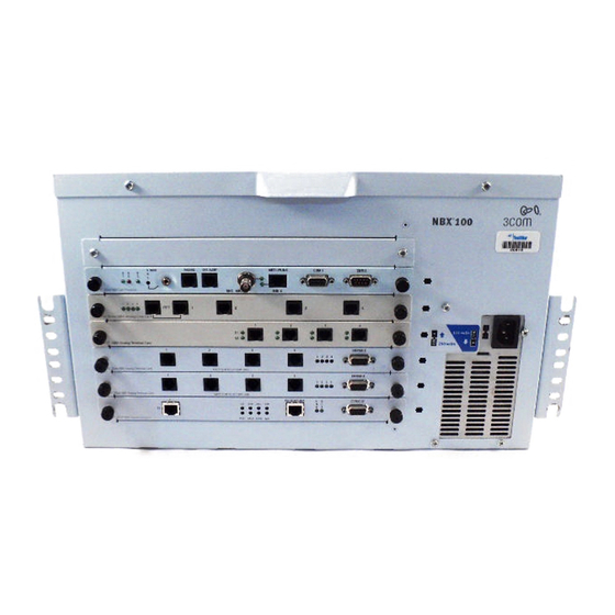
NBX Gateway Chassis. Table 4 describes the items that you must purchase, assemble, and connect to the chassis. See your 3Com NBX Voice-Authorized Partner for purchasing details. CAUTION: If you are using the 3Com SuperStack II ARPS (Advanced... - Page 26 10BT UPLINK CONSOLE 115 volts 230 volts Nominal MDI-X 3C10116C 3Com NBX Digital Line Card 1 2 3 4 3C10114C 3Com NBX Analog Line Card 1 2 3 4 3C10114C 3Com NBX Analog Line Card 1 2 3 4 3C10114C 3Com NBX Analog Line Card Up to six cards slide into the front of the chassis.
-
Page 27: Nbx 100 Call Processor
Figure 4 Figure Figure 4 NBX 100 Call Processor (3C10110C) 10BT UPLINK PAGING EXT. ALERT COM 1 COM 2 3C10110C 3Com NBX Call Processor BNC 10B2 MDI-X Figure 5 NBX 100 Call Processor (3C10110D) PAGING EXT. ALERT 10BT UPLINK COM 1... - Page 28 1: I HAPTER NTRODUCTION If S1 and S2 are both on, the operating system software has not ■ started successfully. If S1 and S2 flash in an alternating pattern, a file system check is in ■ progress, possibly due to an improper shutdown, and the boot process will take longer than normal.
-
Page 29: Overview Of Nbx Cards And Devices
Figure 7 NBX Analog Line Card (3C10114C) CONSOLE 1 2 3 4 3C10114C 3Com NBX Analog Line Card LS Functionally, 3C10114 and 3C10114C are identical. However, 3C10114C uses some different internal components so that 3C10114C requires NBX software release R4.1 or higher. -
Page 30: T1 Digital Line Card
1: I HAPTER NTRODUCTION Initialization (Release R4.1 and higher): Fast steady blink – Waiting for software download. ■ Solid on – Software has been downloaded. The flash memory on ■ the board is being loaded. Slow, non-symmetric blinking pattern – Waiting for the ■... - Page 31 Figure 8 T1 Digital Line Card (3C10116C) 10BT UPLINK CONSOLE Nominal MDI-X 3C10116C 3Com NBX Digital Line Card Figure 9 T1 Digital Line Card (3C10116D) T1 Digital Line Card has the following lights and 3C10116C connectors: T1 — This RJ-48C connector makes a patch cord connection to a T1 ■...
- Page 32 1: I HAPTER NTRODUCTION The 3C10116D T1 Digital Line Card has the following lights and connectors: T1 — This RJ-48C connector makes a patch cord connection to a T1 ■ interface. Status Lights — These lights indicate the status of the T1 card’s ■...
- Page 33 Overview of NBX Cards and Devices network path, the download can take a few minutes. If the DNLD light remains amber, it can indicate a severely congested network or a hardware problem with the T1 card. CALL — Call audio traffic ■...
-
Page 34: E1 Digital Line Card
1: I HAPTER NTRODUCTION E1 Digital Line Card The E1 Digital Line Card, used outside of North America, provides E1 connectivity using the ISDN PRI protocol. It carries data at a rate of 2.048 Mbps and can carry 32 channels, each with 64 Kbps. Thirty of these channels are available for calls. - Page 35 Overview of NBX Cards and Devices RA — On indicates a Remote Alarm. The far end of the E1 line is ■ not receiving appropriate signaling from the E1 board. LB — On indicates that loop-back testing is going on. ■...
- Page 36 1: I HAPTER NTRODUCTION light goes to amber after the connection has been established, it can mean that an active control channel connection through the PRI line has been lost. DNLD — Download ■ Flash — The card is downloading software from the NBX Network Call Processor.
-
Page 37: Bri-St Digital Line Card
If you require an alternative (bare wire-end) cable to use with the ISDN PRI Digital Line Card, contact your 3Com NBX Voice-Authorized Partner. CAUTION: This equipment does not operate when the main power fails. BRI-ST Digital Line... -
Page 38: 10Base-T Uplink Card
HAPTER NTRODUCTION 10BASE-T Uplink Card The 10BASE-T Uplink Card provides eight 10BASE-T Ethernet ports to connect 3Com Telephones (or other 10BASE-T devices) to the LAN. The Uplink Card ( replaces the 10BASE-T Hub Card (3C10115). 3C10370) Figure 13 NBX Uplink Card (3C10370) - Page 39 Overview of NBX Cards and Devices Figure 14 NBX Analog Terminal Card (3C10117B-INT) CONSOLE 1 2 3 4 3C10117B-INT 3Com NBX Analog Terminal Card NOT FOR TELECOM USE Figure 15 NBX Analog Terminal Card (3C10117C) CONSOLE 1 2 3 4...
-
Page 40: Analog Terminal Adapters
Using a terminal emulation program such as Hyperterm, you can access the ATA and use diagnostic and troubleshooting commands. Only qualified 3Com service personnel should use the serial diagnostic port. The Analog Terminal Adapter... - Page 41 10101 — Serial port for diagnostics. ■ POTS — A connection for an analog telephone or fax machine. ■ PC — Provides a connection for a network device such as a 3Com ■ telephone. LAN — Provides a connection to the network.
-
Page 42: 3Com Telephones
Mbps switch with two ports. One port connects the telephone to the LAN and the other port can be used to connect a computer to the LAN. 3Com Telephones that have the IR designation in their part numbers, such as... - Page 43 Overview of NBX Cards and Devices Figure 20 3Com Business Telephone Model 3102 3C10402A Figure 21 3Com Business Telephone Model 1102, 2102, or 2101-IR 3C10121 3C10226B 3C10226PE 3C10281B 3C10281PE 3C102281IRB 3C10281IRPE...
- Page 44 CAUTION: To avoid damage to the 3Com telephone, do not connect a 3Com telephone or Attendant Console directly to a standard telephone line. Although the RJ-11 connector for a traditional telephone fits into the 3Com telephone’s RJ-45 jack, the electrical interfaces are not compatible...
-
Page 45: Attendant Console
Telephone Guide for details about how to use an Attendant Console. Third-party Devices 3Com works with third-party suppliers to provide a range of devices that are compatible with NBX systems. For more information on third-party devices, see your 3Com NBX Voice-Authorized Partner. For information on how to install, configure, and manage a third-party device, see the documentation that comes with the device. -
Page 46: Overview Of Application Software
■ 3Com Network Supervisor ■ LabelMaker utility ■ Quick Reference Guides for the 3Com Business Telephones, 3Com ■ Basic Telephones, and telephones connected to the NBX system through a port on the Analog Terminal Card or the Analog Terminal Adapter... -
Page 47: System Configuration Guidelines
The NBX systems count many physical devices and certain software applications as devices toward the total device limit: Physical Devices — Each 3Com Telephone, each Analog Terminal ■ Adapter, each channel on a Digital Line Card, and each port on an Analog Line Card counts as one device. -
Page 48: Individual Device Limits
Certain individual devices and applications have count limits that are Limits governed by licenses. (See the 3Com Price List or your 3Com NBX Voice-Authorized Partner for details on available incremental licences.) Example: You can install a license for 2 Virtual Tie Lines (VTLs), and then add incremental 2-unit licenses up to a limit of 8 VTLs on an NBX 100 system or up to 48 VTLs on a SuperStack 3 NBX system. -
Page 49: Table Of Maximum Device Counts
375 cards (1500 ports) 50 cards (200 ports) CAUTION: SuperStack 3 NBX: If you are using the 3Com SuperStack II ARPS (Advanced Redundant Power Supply) as a backup power supply for the NBX Gateway Chassis, you are limited to two ATC cards of version 3C10117 or... - Page 50 1: I HAPTER NTRODUCTION Table 5 Supported Features on the SuperStack 3 NBX and NBX 100 Call Processors (continued) Per-Unit Device Count Maximum Number Toward Total System Per SuperStack 3 Maximum. Number Count System Per NBX 100 System ATA (NBX Analog Terminal 1500 Adapter) NBX Analog Line Card...
-
Page 51: Installing System Hardware Components
NSTALLING YSTEM ARDWARE OMPONENTS This chapter explains how to install standard and optional hardware ® ® components for the NBX 100 and SuperStack 3 NBX Networked Telephony Systems. It covers these topics: Introduction ■ International Feature Support ■ Installation Requirements ■... -
Page 52: Introduction
The NBX Analog Terminal Adapter and each port on the NBX Analog Connectors Terminal Card may require a telephone connector for use outside North America. Contact your 3Com NBX Voice-Authorized Partner for information on country-specific requirements. Language Support The NBX Resource Pack CD includes these localized components: Telephone tones and cadences that match those used by telephone ■... -
Page 53: Installation Requirements
“Using a Powered Ethernet Cable to Power the Telephone” Chapter 3 for more information. CAUTION: 3Com strongly recommends that you use UL listed surge suppression devices for the telephones and the local telephone lines and an uninterruptible power supply for each NBX chassis. Environmental You can install the NBX system in any clean, dry, well-ventilated location. -
Page 54: Physical Requirements
2: I HAPTER NSTALLING YSTEM ARDWARE OMPONENTS Physical You can install an NBX 100 chassis in a standard equipment rack or Requirements mount the chassis on a wall. You must mount a SuperStack 3 NBX Call Processor or a SuperStack 3 NBX Gateway Chassis in an equipment rack. Verify that the site meets these physical requirements: The NBX system must be installed in a secure area. -
Page 55: Local Telephone Service
Each analog telephone line has dial tone. ■ CAUTION: 3Com strongly recommends that you use UL-listed surge suppression devices on all local telephone lines. If you are installing an optional BRI-ST, T1, or E1 Digital Line Card, ■... -
Page 56: Does The Telephone Company Need To Be Involved
NBX system through an Analog Terminal Adapter, reserve at least one telephone line for the fax machine. CAUTION: To avoid damage to any 3Com telephone, do not connect it directly to a standard telephone line. Although the RJ-11 connector for a traditional telephone fits into the 3Com telephone’s RJ-45 jack, the... -
Page 57: What External Devices Can Connect To An Nbx System
Installation Questions 3Com 3101, 3101SP, 3102, and 3105 devices support Power over ■ Ethernet (PoE). They do not come with AC power adapters. You can power these devices with any IEEE 802.3af-compliant power source or with optional AC power adapters. The packing sheet that ships with each device shows the device power options. -
Page 58: How Many Telephones Or Devices Does The Nbx System Support
■ Each ConneXtions H.323 port ■ Examples: With 300 3Com telephones, a SuperStack 3 NBX system can ■ accommodate up to 1200 additional devices, in any combination of card ports, Attendant Console, T1 channels, and so on. With 124 telephones, an NBX 100 system can have no more than 76 ■... - Page 59 The receiving NBX device can be another 3Com telephone, or for external calls, it can be an Analog Line Card port or a channel on a Digital Line Card.
-
Page 60: Before You Begin Installation
2: I HAPTER NSTALLING YSTEM ARDWARE OMPONENTS Low-bandwidth Connections You can configure a telephone to operate in lower-bandwidth environments such as a single B channel of a BRI ISDN line or other links with bandwidth as low as 56 Kbps. The preferred method for enabling this is to select G729 audio, ■... -
Page 61: Important Safety Information
Important Safety Information Test set ■ Four rack screws appropriate to the rack (if rack mounting the chassis) ■ Important Safety Before you install or remove any components or perform any Information maintenance procedures on the system, you must read the following safety information. - Page 62 Do not staple the NBX power cord or otherwise attach it to building ■ surfaces. Do not use any AC power converter on a 3Com Basic Telephone, ■ Business Telephone, or Attendant Console other than the one that is shipped with the device. On the Model 3102 Business Telephone and Model 3101 Basic Telephone, the power converter is an optional component.
- Page 63 Important Safety Information For countries outside of Europe, you must use a power cord set ■ that complies with the relevant national standards for cable type and appliance coupling. Table 6 Regulatory Requirements Country or Region Power Cord Set Details Europe The supply plug must comply with CEE 7/7 (“SCHUKO”) ■...
-
Page 64: Lithium Battery Safety
Safety WARNING: The battery is not field replaceable. If you suspect a battery failure, contact your 3Com NBX Voice-Authorized Partner. There is a danger of explosion if the battery is incorrectly replaced. Replace the battery only with the same or equivalent type as recommended by the manufacturer. - Page 65 Consignes Importantes de Sécurité Table 7 Cordon Électrique Pays ou Region Détails du Cordon Électrique Europe La prise secteur doit être conforme aux normes CEE 7/7 ■ (“SCHUKO”) Le cordon secteur doit porter la mention <HAR> ou ■ <BASEC> et doit être de type HO3VVF3GO.75 (minimum). Royaume-Uni La prise secteur doit être conforme aux normes BS1363 ■...
-
Page 66: Batterie Au Lithium
2: I HAPTER NSTALLING YSTEM ARDWARE OMPONENTS Batterie au lithium Veuillez lire attentivement la note suivante. AVERTISSEMENT: Le remplacement incorrect de batterie au lithium présente un risque d’explosion. Remplacez cette batterie par une batterie identique ou de type équivalent, en respectant les recommandations du constructeur. -
Page 67: Lithiumbatterie
Wichtige Sicherheitsinformationen Table 8 Anschlußkabelsatz (continued) Land Anschlußkabelsatz Vereinigtes Der Netzstecker muß die Norm BS1363 (13 Ampere, 3 Stifte) ■ Königreich erfüllen und mit einer 5-A-Sicherung gemäß Norm BS1362 ausgestattet sein. Das Netzkabel muß vom Typ HO3VVF3GO.75 ■ (Mindestanforderung) sein und die Aufschrift <HAR> oder <BASEC>... -
Page 68: Unpacking And Examining The Components
After a card is inserted into a chassis, the MAC address is not visible. When you install cards into the chassis, 3Com recommends that you install one card at a time, and that you install the cards in the order of the MAC addresses. -
Page 69: Installing The Nbx 100 Chassis
Drive configuration database, and NBX Messaging software. 3Com recommends that you install the disk drive in the chassis before you mount the chassis on a wall or in a rack. A system requires only one Call Processor and disk drive, even when you have more than one chassis. - Page 70 2: I HAPTER NSTALLING YSTEM ARDWARE OMPONENTS To install the disk drive in the NBX 100 chassis: 1 Remove the top cover of the NBX 100 chassis. Use a Phillips screwdriver to remove the screws from the top-front of the NBX 6-slot chassis. Pull the cover forward slightly, and then lift it from the chassis.
-
Page 71: Mounting The Nbx 100 Chassis
Installing the NBX 100 Chassis 4 Using the four 6-32 Phillips head screws provided, attach the disk drive to the chassis, above the power supply, as shown in Figure 5 Route the data cable through the rectangular opening in the chassis inner wall. - Page 72 2: I HAPTER NSTALLING YSTEM ARDWARE OMPONENTS Mounting the NBX 100 Chassis in an Equipment Rack To mount the NBX 100 chassis in an equipment rack: Verify that the equipment rack is properly installed and grounded and that the installation area is properly ventilated. 1 Attach the two mounting brackets securely to the sides of the NBX 100 chassis, using the upper and lower holes in each of the brackets and the two holes near the front of the chassis.
- Page 73 Installing the NBX 100 Chassis do not mount multiple chassis side by side. If you do, one chassis draws in warm air from the other, limiting the effectiveness of the cooling fans. 1 Install the brackets at the back of the chassis, as shown in Figure Figure 27 Attaching Wall Mounting Brackets to the NBX 100 Chassis 2 Use the dimensions shown in...
-
Page 74: Powering Your Nbx 100 System
2: I HAPTER NSTALLING YSTEM ARDWARE OMPONENTS 5 Lift the chassis and slide the two keyed mounting brackets over the screws in the wall. 6 While holding the chassis in place, install screws into the top holes of each mounting bracket, and then tighten all four screws. Powering Your To turn on power to the NBX 100 system: NBX 100 System... -
Page 75: Mounting The Nbx Gateway Chassis
Installing the SuperStack 3 NBX System SuperStack 3 Figure 29 Installing the NBX Call Processor NBX Call Processor External KYBD Mouse Video Com 1 Com 2 Ethernet 1 Ethernet 2 Paging Alert SuperStack 3 NBX 1 Install one screw into each vertical rail of the 19-inch rack. Leave at least 6.5 cm (2.5 inches) above other equipment in the rack. -
Page 76: Installing A Second Disk For Disk Mirroring
2: I HAPTER NSTALLING YSTEM ARDWARE OMPONENTS Installing a Second Disk mirroring provides the ability to run a second disk in parallel with Disk for Disk the first. For more detailed information about disk mirroring, see “Disk Mirroring Mirroring” in the NBX Administrator’s Guide. Disk Mirroring is an optional feature. -
Page 77: Powering Your Superstack 3 Nbx System
Installing the SuperStack 3 NBX System Powering Your To turn on power to the SuperStack 3 NBX Call Processor and the SuperStack 3 NBX NBX Gateway chassis, follow these steps: System 1 Attach a power cord to the back of each chassis. If your SuperStack 3 NBX Call Processor has redundant power supplies, connect both power cords to both power connectors. -
Page 78: Configuring Nbx System Networking
2: I HAPTER NSTALLING YSTEM ARDWARE OMPONENTS Table 9 SS3 NBX Disk LED States (continued) Explanation LED 1 LED 2 LED 3 Flash codes indicate disk problem: Flashing Flashing 2 flashes: No valid disk (system is halted) ■ 3 flashes: Two valid disks, but they are not ■... -
Page 79: Establishing Ip Connectivity
Configuring NBX System Networking Establishing IP You need IP connectivity to use the NBX NetSet utility to configure and Connectivity manage the NBX system.You do not need to install any special software to run the NBX NetSet utility, but your computer must have Microsoft Internet Explorer 5.5 or higher, which enables access the NBX NetSet utility, the configuration interface for the NBX system. - Page 80 2: I HAPTER NSTALLING YSTEM ARDWARE OMPONENTS Overview of how to change the IP settings of the NBX system: Temporarily change the IP address of your computer to conform with ■ the default IP settings of the NBX system. Connect your computer to the NBX system. ■...
- Page 81 Configuring NBX System Networking If the connection attempt fails, check the browser’s Proxy Server setting and verify that it is configured for a direct connection. Also, check the Connection setting and verify that it is set for a direct LAN connection, not a dial-up connection.
-
Page 82: Configuring Ip Addresses For Your Lan
2: I HAPTER NSTALLING YSTEM ARDWARE OMPONENTS Table 10 IP Addressing and the NBX System (continued) Local IP Environment NBX System Configuration Private IP network, with subnets You probably need to change the NBX system IP address to conform with the existing address space. -
Page 83: Connecting Cards And Devices
You do not need to connect cards to each other within a chassis. They are connected by the chassis backplane. Do not connect telephone lines or 3Com telephones yet. Establishing SuperStack 3 NBX LAN Connections Connect the SuperStack 3 NBX Call Processor to your LAN using the Ethernet 1 port. -
Page 84: Connecting Analog Line Cards
“Using Auto Discover for Initial System Configuration” page 3Com recommends that you install the cards in MAC address order. This practice makes it easier to diagnose and troubleshoot problems. Mapping Line Card Ports to Telephone Lines You can run the system using the default configuration, but to have... -
Page 85: Connecting Digital Line Cards
Connecting Cards and Devices Connecting Digital You can install cards with the power on. To connect and configure the Line Cards digital line cards: 1 Remove one of the blank faceplates from the chassis. 2 Install the card securely. Verify that the edges of the card ride in the chassis guide slots, and then slide the card in until you feel slight resistance. -
Page 86: Connecting An Analog Terminal Adapter
2: I HAPTER NSTALLING YSTEM ARDWARE OMPONENTS Connecting an If you are installing one or more Analog Terminal Adapters (ATA), install Analog Terminal them after installing chassis cards. Adapter To install an ATA: 1 Connect the analog telephone or fax machine to the analog port on the ATA. - Page 87 Connecting Cards and Devices 7 If the ATA is connected to a fax machine, configure the port for fax usage: a Open the NBX NetSet utility and go to Device Configuration > ATA. b Select the ATA from the list and click Modify. c Enable the check box labeled Fax Machine, then click Apply.
-
Page 88: Connecting A 3Com Attendant Console
(24-port) power connection. CAUTION: You can damage an NBX device by using an NBX power splitter (3C10223) with the 3Com Network Jack Power over Ethernet Multiport Midspan Solution (3CNJPSE24). Use the NBX power splitter (3C10223) only with the 3Com Ethernet Power Source (3C10220, 12-port, or 3C10222, 24-port). - Page 89 System Configuration > System Settings > System-wide and then enable the check box labeled Auto Discover Attendant Consoles. Attendant Console Notes An Attendant Console must be associated with only one 3Com ■ telephone. When you Auto Discover an Attendant Console, the NBX...
-
Page 90: Selecting Regional Software And Components
5 In the Modify Attendant Console window, select a telephone from the list. 6 Click Apply and review your changes. 7 Click OK to close the dialog box. For more information on configuring and using the 3Com Attendant Console, see Chapter Selecting Regional... -
Page 91: Using Auto Discover For Initial System Configuration
Initial System “Devices” include telephones, Analog Line Cards, Digital Line Cards, Configuration Analog Terminal Adapters, 3Com Attendant Consoles, and “virtual devices” such as the pcXset Soft Telephone and the ConneXtions H.323 Gateway. After a device has been discovered, the Auto Discover process does not find that device again. - Page 92 (receptionist). 3Com Attendant Console Finds and configures any installed 3Com Attendant Consoles. The first 100 existing telephones, except for the extension that is associated with the Attendant Console, are mapped to Attendant Console buttons. The lowest extension is automatically associated with the Attendant Console.
-
Page 93: Initial System Configuration
. The System Settings dialog box appears (Figure 33). System-wide Figure 33 System Settings Dialog Box 5 Select the check box for the device you are configuring. 3Com recommends that you Auto Discover one device type at a time. Table 14 describes each choice. - Page 94 MAC address. If you are installing a 3Com Attendant Console, connect it after you have discovered all of the telephones. The Auto Discover Attendant Consoles process maps all existing telephone extension to the Attendant Console.
-
Page 95: Disabling The Auto Discover Feature
Auto Extension setting for each line card port. Button Mappings enable you to map a line card port extension to a specific Access button on a 3Com telephone. Button Mappings identify the telephones that ring when a call comes in on the mapped CO line. -
Page 96: Reassigning Extensions And Setting Line Card Port Options
2: I HAPTER NSTALLING YSTEM ARDWARE OMPONENTS PBX mode is the easiest configuration to set up and manage. Key mode requires more configuration because you must map the CO lines to telephones. By using pooled lines, mapped lines, a receptionist telephone, and the Automated Attendant, you can configure the NBX system to support a wide range of operational requirements. - Page 97 Caller ID. Bandwidth Considerations settings allow you to change the amount of bandwidth used by this port. 3Com recommends that you use default values and change these settings only when you have bandwidth constraint issues that you cannot solve by...
- Page 98 2: I HAPTER NSTALLING YSTEM ARDWARE OMPONENTS Table 15 Modify Line Card Port Fields (continued) Field Purpose Set All For Turns on data compression and other measures designed to reduce the packet stream to a minimum Bandwidth Enable the Low Bandwidth check box for a telephone you link to the Connection network by a low bandwidth connection such as an ISDN line.
- Page 99 Using Auto Discover for Initial System Configuration To reassign the extension numbers: 1 Record the extensions and either the MAC addresses or port numbers for the four Line Card ports. For the 3C10114 board, record the MAC addresses. Each port has a unique MAC address.
-
Page 100: Connecting Telephone Lines
1 Use a nonferrous (plastic or aluminum) adjustment tool to adjust the volume control on the front of the Call Processor to about mid-range. 2 Use a 3Com Telephone to call another extension, and have the person put you on hold. -
Page 101: Configuring Routing Devices
Configuring Routing Devices Configuring If you have a low-bandwidth device on the LAN, such as an ISDN router, Routing Devices you must update the device’s routing table to filter NBX system multicast addresses. The NBX system uses Ethernet multicast addresses to implement some system features. - Page 102 2: I HAPTER NSTALLING YSTEM ARDWARE OMPONENTS...
-
Page 103: Telephones And Attendant Consoles
Adding Telephones This section tells you how to add 3Com Business and Basic Telephones to the NBX system. Before you can Auto Discover any licensed devices, you must enter the device license into the system. - Page 104 DC power symbol: Using a Powered Ethernet Cable to Power the Telephone To eliminate the power converter, you can connect your 3Com Telephone to a powered Ethernet cable. NBX devices can use Ethernet power directly or through the use of one of two types of splitter devices.
- Page 105 NBX devices work with these Ethernet power sources: Ethernet power sources that comply with the IEEE 802.3af standard, ■ commonly called Power over Ethernet or PoE 3Com Ethernet power sources that predate the IEEE 802.3af standard ■ Table 19 for power connection instructions.
- Page 106 If you connect both a power brick and a powered Ethernet cable to a “PE” or a 3101, 3101SP, or 3102 3Com Telephone, the telephone uses the Ethernet power if it is available and uses the power brick power only if Ethernet power is removed.
- Page 107 3101 and 3101SP Basic Telephones 2101 Basic Telephone CAUTION: You can damage an NBX device by using an NBX power splitter (3C10223) with the 3Com Network Jack Power over Ethernet Multiport Midspan Solution (3CNJPSE24). Use the NBX power splitter (3C10223) only with the 3Com Ethernet Power Source (3C10220, 12-port, or 3C10222, 24-port).
- Page 108 3: T HAPTER ELEPHONES AND TTENDANT ONSOLES Figure 34 Connections for 3Com 3102 Business Telephones Power cable. Ask your Administrator how you should power your phone. Then see Table 19 for instructions on how to connect your telephone to power.
- Page 109 Ethernet cable (optional; to connect a computer or an Attendant Console to the network) Handset cord (to handset) Ethernet cable (to data jack) Figure 37 Connections for 3Com 3101 and 3101SP Basic Telephones Power cable. Ask your Administrator how you should power your phone. Then see Table 19 for instructions on how to connect your telephone to power.
- Page 110 Connecting a Computer to the Telephone 3Com telephones contain a two-port Ethernet switch with connectors on the underside of the phone. One port is used to connect the telephone to the LAN and the other port connects a computer or other Ethernet device to the LAN.
- Page 111 Adding Telephones Adding a New Telephone Using the Auto Discover Feature Before you enable the Auto Discover feature, be sure that you have the dial plan you want installed. The NBX 100 ships with a default 3-digit dial plan starting at extension 100. The SuperStack3 NBX ships with a default 4-digit dial plan starting at extension 1000.
- Page 112 3: T HAPTER ELEPHONES AND TTENDANT ONSOLES Figure 40 System Settings - System-wide Dialog Box 3 Clear all check boxes associated with Auto Discover. 4 Enable the Auto Discover Telephones check box. 5 Optionally, enable the Auto Add Phones to Call Pickup Group 0 check box.
-
Page 113: Adding A 3Com Attendant Console
8 When you connect the telephone to the LAN and power, the extension appears on the display panel. Adding a 3Com The 3Com Attendant Console provides extension button mappings and Attendant Console displays the current status of each mapped extension. A receptionist typically uses the Attendant Console to connect incoming calls to telephone extensions. - Page 114 ELEPHONES AND TTENDANT ONSOLES The 3Com 3105 Attendant Console complies with the IEEE 802.3af standard, commonly called Power over Ethernet (PoE), so a power converter is an optional component. To use a power converter, order power adapter 3C10224-XX, where XX is the country code: AA (Australia/New Zealand) ■...
-
Page 115: Auto Discover An Attendant Console
Adding a 3Com Attendant Console Table 20 Connecting Power to a 3Com Attendant Console (continued) Power Source Connection Details Power over Ethernet (802.3af-compliant) The 3105 is compliant with 802.3af. You can power source connect a powered Ethernet cable 1, directly to the device’s Ethernet connector. - Page 116 If there are no other Attendant Consoles on the system, the Auto ■ Discover process associates the new Attendant Console with the 3Com Business or Basic Telephone that has the lowest extension number. If one or more Attendant Consoles are already configured in the ■...
-
Page 117: Verifying Extension Assignments On An Attendant Console
To download the LabelMaker utility: 1 Log into NBX NetSet as an administrator. 2 Click Downloads > LabelMaker. After you print the labels and then cut them out, remove the plastic cover from the Attendant Console and install the labels. On the 3Com 3105... -
Page 118: Adding A Remote Telephone
Ethernet ports. You connect the 3Com Telephone directly to one of the Ethernet ports. Another option is use the pcXset soft telephone application instead of a 3Com Telephone. -
Page 119: Analog Line Cards
NALOG ARDS This chapter tells you how to install and how to verify the successful installation of Analog Line Cards. For information about installing the system hardware components, see Chapter Each NBX Analog Line Card provides access for up to four analog telephone lines into your NBX system. -
Page 120: Inserting An Analog Line Card
4: A HAPTER NALOG ARDS Inserting an When you insert an Analog Line Card into the chassis, you may leave the Analog Line Card system powered up. The Auto Discover process begins as soon as the system senses the new card. To insert the Analog Line Card: 1 Find the MAC address of the card on the label on the card. -
Page 121: Using Status Lights
Verifying an Analog Line Card MAC addresses, with the associated port numbers and assigned extensions. Table 21 MAC Addresses for the Ports on an Analog Line Card ATA Card or Port MAC Address Extension Port 1 00:e0:bb:03:91:45 7251 Port 2 00:e0:bb:03:91:46 7250 Port 3... - Page 122 4: A HAPTER NALOG ARDS...
-
Page 123: Analog Devices
A user cannot forward calls to voice mail by enabling a button such as ■ the FWD MAIL button on the 3Com Business Telephone. You can use a feature code to have the system automatically transfer calls to voice mail if your analog telephone is not answered. -
Page 124: Adding An Analog Terminal Card
3 Clear all check boxes associated with Auto Discover. 4 Click the Auto Discover Telephones check box to select it. The Auto Discover Telephones check box enables and disables the Auto Discover process for Analog Terminal Cards, Analog Terminal Adapters, and 3Com Telephones. 5 Click OK. -
Page 125: Inserting An Analog Terminal Card
Inserting an Analog Terminal Card Inserting an Analog When you insert the ATC into the chassis, you may leave the system Terminal Card powered up. The Auto Discover process begins as soon as the system senses the new card. Functionally, ATCs 3C10114 and 3C10114C are identical. However, 3C10114C uses some different internal components so that 3C10114C requires NBX software release R4.1 or higher. -
Page 126: Verifying Analog Terminal Card Ports
5: A HAPTER NALOG EVICES Verifying Analog After you have used the Auto Discover feature to add an Analog Terminal Terminal Card Ports Card, you can verify that the card is properly installed by using the NBX NetSet utility, described next, and by examining the status lights on the front of the card, which are described on page 127. -
Page 127: Using Status Lights
System-wide) is how you enable the Auto Discover feature for the four ports on each Analog Terminal Card, the single port on each Analog Terminal Adapter, and for 3Com Telephones. You might find that the NBX system does not assign extension numbers to ports on an Analog Terminal Card in the order of the MAC addresses. -
Page 128: Adding An Analog Terminal Adapter (Ata)
Auto Discover feature. You Auto Discover an Analog (ATA) Terminal Adapter (ATA) in the same way that you discover 3Com telephones and Analog Terminal Cards. 1 In the NBX NetSet - Main Menu window, click System Configuration. The System Configuration dialog box appears. -
Page 129: Connecting The Analog Terminal Adapter
Connecting the Analog Terminal Adapter Connecting the After you have enabled the Auto Discover feature, connect the Analog Analog Terminal Terminal Adapter (ATA) to the same network segment as the one on Adapter which the call processor resides. To connect the ATA: 1 Connect the AC power converter provided with the ATA to the power connector on the ATA. -
Page 130: Verifying An Analog Terminal Adapter
ATA’s LAN port (labeled LAN) and power connection (labeled CAUTION: You can damage an NBX device by using an NBX power splitter (3C10223) with the 3Com Network Jack Power over Ethernet Multiport Midspan Solution (3CNJPSE24). Use the NBX power splitter (3C10223) only with the 3Com Ethernet Power Source (3C10220, 12-port, or 3C10222, 24-port). -
Page 131: Using Status Lights
Verifying an Analog Terminal Adapter Figure 44 Device Configuration Dialog Box — ATA Tab 3 Use the MAC address that you recorded prior to installing the ATA to identify it in the list. The MAC address on the ATA and the MAC address displayed in the list on the ATA tab should be identical. - Page 132 5: A HAPTER NALOG EVICES...
-
Page 133: Bri-St Digital Line Card
BRI-ST D IGITAL This chapter tells you how to install and verify the successful installation of the ISDN BRI-ST (Basic Rate Interface) Digital Line Card. For information about installing the system hardware components, see Chapter The following sections describe how to add and configure a BRI-ST Digital Line Card to handle four BRI spans using the ST interface. -
Page 134: Adding A Bri-St Digital Line Card
6: BRI-ST D HAPTER IGITAL Adding a BRI-ST To add an ISDN BRI-ST Digital Line Card to an NBX system, use the Digital Line Card information in these sections: Preparing the NBX System for BRI Cards ■ Ordering DID, CLIP, and MSN Services for BRI ■... -
Page 135: Enabling The Auto Discover Feature
Adding a BRI-ST Digital Line Card 617-555-4100 through 617-555-4299. If the local telephone carrier passes you three digits, you need no translator entries in the Dial Plan configuration file. If the carrier passes you four digits, you could add a single set of translator entries to the configuration file to remove the first digit (4) and use the remaining three digits as the internal extension. -
Page 136: Verifying A Bri-St Digital Line Card
6: BRI-ST D HAPTER IGITAL 7 Wait 3 minutes (more on a SuperStack 3 NBX system with many devices) for the system to discover the BRI-ST card and update the database. When you insert the BRI-ST Digital Line Card, it begins an initialization sequence. - Page 137 Verifying a BRI-ST Digital Line Card After you connect an ISDN BRI span to a port on the BRI-ST Digital Line Card, the D light turns green if the span is operating properly, and turns amber if there is a problem. For a span that is operating properly, when the NBX system initiates a call on a B channel, the corresponding light initially turns amber.
- Page 138 6: BRI-ST D HAPTER IGITAL...
-
Page 139: E1 Isdn Pri Digital Line Card
E1 ISDN PRI D IGITAL This chapter tells you how to install and how to verify the successful installation of an E1 Digital Line Card. For information about installing system hardware, see Chapter This section describes how to add an E1 Digital Line Card and how to connect to an E1 service provided by the local telephone company. -
Page 140: Adding An E1 Digital Line Card
7: E1 ISDN PRI D HAPTER IGITAL Adding an E1 The following sections tell you how to add an E1 Digital Line Card to an Digital Line Card NBX system: Preparing the NBX System for E1 Cards ■ Ordering DID, CLIP, and MSN Services for E1 ■... -
Page 141: Enabling The Auto Discover Feature For Digital Line Cards
Adding an E1 Digital Line Card If the DDI/DID numbers match your internal extension numbers, the translator entries in your Dial Plan configuration file can be much simpler. Example: You plan to use internal extensions from 100 through 299, and the local telephone company assigns you numbers from 617-555-4100 through 617-555-4299. -
Page 142: Verifying An E1 Digital Line Card
7: E1 ISDN PRI D HAPTER IGITAL CAUTION: If you cannot seat the card with light pressure, remove it and check for obstructions. 5 Tighten the left and right screws on the front of the E1 card. 6 Wait 3 minutes (more on a SuperStack 3 NBX system with many devices). When you insert the E1 Digital Line Card, it begins an initialization sequence. -
Page 143: Using The Status Lights
Verifying an E1 Digital Line Card Using the Status You can use the E1 Digital Line Card status lights to verify that the E1 card Lights was properly discovered. 3C10165C — After the Auto Discover process has completed, and before you connect the E1 Digital Line Card to the telephone company’s E1 line, the CF (Carrier Fail) light should appear solid green. - Page 144 7: E1 ISDN PRI D HAPTER IGITAL...
-
Page 145: T1 Digital Line Card
T1 D IGITAL This chapter tells you how to install a T1 Digital Line Card. In the NBX NetSet utility, digital line cards are referred to as either cards or boards. The following sections describe how to add a T1 Digital Line Card (3C10116C and 3C10116D) and how to connect to a T1 service provided by the local telephone company: Adding a T1 Digital Line Card... -
Page 146: Adding A T1 Digital Line Card
8: T1 D HAPTER IGITAL The NBX system provides E911 (emergency) connectivity if the T1 ■ Digital Line Card is configured for ISDN PRI (Primary Rate Interface) signaling. The system provides the calling number (ANI) so that the emergency services personnel can determine the location of the caller from the E911 database. -
Page 147: Enabling Auto Discover For Digital Line Cards
Adding a T1 Digital Line Card into extension number 4295, and a sequence such as 4213 into 4713. The configuration would require several translator entries to handle subsets of the total range. A unique set of entries would handle incoming digit sequences from 3500 through 3599, from 3600 through 3699, and each of the other sequences in which the first two digits were unique in the range from 37XX through 44XX. -
Page 148: Verifying The T1 Digital Line Card
8: T1 D HAPTER IGITAL 3 Select a slot for the T1 card in the chassis and use a Phillips screwdriver to remove the blank faceplate from the slot. 4 Insert the T1 card into the slot. 5 Slide the T1 card into the chassis until you feel it touch the connectors. 6 To seat the T1 card into the connectors, apply firm pressure to both the left and right sides of the front of the card. -
Page 149: Using The Status Lights
Verifying the T1 Digital Line Card 6 Scroll through the list of channels to verify that 24 channels appear in the list. Using the Status To verify the presence of a Digital Line Card in the system, you can use Lights the status lights on the front of the card. - Page 150 8: T1 D HAPTER IGITAL...
-
Page 151: Configuring Ip Telephony
IP T ONFIGURING ELEPHONY This chapter describes IP telephony and provides instructions for configuring IP. It covers these topics: IP Telephony Overview ■ Implementing IP ■ Standard IP Configuration ■ IP On-the-Fly Configuration ■ Providing the NCP IP Address to Devices ■... -
Page 152: Ip Telephony Overview
9: C IP T HAPTER ONFIGURING ELEPHONY IP Telephony You can integrate the NBX system into any network infrastructure Overview because it can operate at either Layer 2 (Ethernet) or Layer 3 (IP). CAUTION: A qualified network design engineer should set up an IP network for the first time. -
Page 153: Standard Ip Configuration
IP addresses to handle the number of telephones and devices in the NBX system. If you are not using a DHCP server, use the NBX NetSet utility to configure an IP address for each 3Com telephone and device. Some telephones are on separate subnetworks. ■... -
Page 154: Ip On-The-Fly Configuration
9: C IP T HAPTER ONFIGURING ELEPHONY IP On-the-Fly The NBX system must be configured differently in each of the following IP Configuration On-the-Fly situations: All telephones and devices are on the same subnetwork as the Call ■ Processor. You do not need to use IP in this environment. Devices always use Ethernet (Layer 2) communications, and the Call Processor never needs to give out an IP address. -
Page 155: Configuring Ip Telephony
Configuring IP Telephony 3C10165D E1 Digital Line Cards and 3C10116D T1 Digital Line Cards do not support DHCP option 184. If your DHCP server is set up to use option 184, you must still manually configure these digital line cards. See the NBX Administrator’s Guide for more information. -
Page 156: Configuring Ip On-The-Fly
9: C IP T HAPTER ONFIGURING ELEPHONY IP On-the-Fly — The NCP provides IP addresses as needed to local ■ devices. Remote devices obtain IP addresses from the DHCP server, or you can manually program their IP addresses. 3C10165D E1 Digital Line Cards and 3C10116D T1 Digital Line Cards do not support the NBX IP On-the Fly feature. -
Page 157: Configuring The Dhcp Server
Configuring IP Telephony 3 Click IP Addresses. 4 In the IP Addresses dialog box, click Add. The Add Dynamic IP Address dialog box appears. 5 Specify an address range, and then click OK. Configuring the DHCP If you choose to use DHCP, contact your network administrator to Server configure the DHCP server. -
Page 158: Entering Data Using The Telephone Key Pad
Telephone Key telephone Local User Interface (LUI) utility. You can start the LUI utility on any 3Com telephone by cycling power to the telephone, and then starting the utility before the telephone finishes its download sequence. Each telephone has a different method of... -
Page 159: Automatically Configuring Telephone Ip Settings
For detailed instructions on how to use the LUI utility, see the NBX Administrator’s Guide. Automatically When you connect a 3Com Telephone to a network, it searches for a Configuring DHCP server. If the telephone is on the same subnet as the NCP, the... -
Page 160: Configuring T1, E1, And Bri Channels
9: C IP T HAPTER ONFIGURING ELEPHONY To manually configure IP settings for line card ports: 1 Log in to the NBX NetSet utility using the administrator username and password. 2 If you have not already done so, use the Auto Discover feature to add line card ports to the configuration database. -
Page 161: Low-Bandwidth Telephony
You cannot configure ConneXtions ports in the IP Settings dialog box. See “ConneXtions H.323 Gateway” in the NBX Administrator’s Guide for more information. Low-bandwidth To support remote users, you can configure a 3Com Business Telephone Telephony or 3Com Basic Telephone to operate over a low-bandwidth link. For... - Page 162 The ability of NBX systems to operate in Ethernet (Layer 2) mode or IP (Layer 3) mode gives you several connection options such as cable modem, frame relay, and DSL. Your 3Com NBX Voice-Authorized Partner can help you to design a system to meet your needs.
-
Page 163: Broadband Telephony
Configuring IP Telephony system. Consult your 3Com NBX Voice-Authorized Partner or a 3Com-qualified service technician for assistance. The specific configuration tasks required for setting up the link between the Call Processor and the remote telephone depend on the type of equipment and the Telco/ISP that you use. - Page 164 9: C IP T HAPTER ONFIGURING ELEPHONY from your home system to the NBX system network, the NBX system must have a public IP address. 2 Use the NBX NetSet utility to enable Auto Discover Telephones (System Configuration > System Settings > System-wide) and then connect the NBX Telephone to the NBX system.
-
Page 165: Troubleshooting
ROUBLESHOOTING This chapter contains maintenance and troubleshooting information that can help you resolve simple problems. It covers these topics: System-level Troubleshooting ■ Connecting a Computer to a Serial Port ■ Servicing the Network Call Processor Battery ■ Getting Service and Support ■... -
Page 166: System-Level Troubleshooting
Call Processor. 2 Wait 60 seconds. 3 Reconnect power to the system. 4 Use NBX NetSet to enter the correct date and time. Problem with Contact your 3Com NBX Network Call Voice-Authorized Partner. Processor battery. Your browser No IP connectivity... - Page 167 System-level Troubleshooting Table 24 Troubleshooting Actions (continued) Symptom Possible Cause Suggested Action Invalid IP The system has a default IP configuration configuration which might need to be changed to match your local IP environment. Temporarily change the IP configuration of your computer so that the subnet configuration matches the system configuration.
-
Page 168: Connecting A Computer To A Serial Port
10: T HAPTER ROUBLESHOOTING Table 24 Troubleshooting Actions (continued) Symptom Possible Cause Suggested Action NBX NetSet is Your network uses a A common networking practice is to very slow in proxy server for employ a proxy server to shield your responding. - Page 169 Connecting a Computer to a Serial Port You can connect a computer directly to the serial port on these devices: Table 25 Serial Port Connections Card Port SuperStack 3 NBX Call Processor COM1 NBX 100 Call Processor COM1 BRI-ST Digital Line Card CONSOLE E1 Digital Line Card CONSOLE...
-
Page 170: Servicing The Network Call Processor Battery
SuperStack 3 NBX system, it could mean that the Call Processor battery Processor Battery must be replaced. The battery is not a user-serviceable item. If you suspect a problem with the battery, contact your 3Com Technical Support representative. WARNING: There is a danger of explosion if the battery is incorrectly replaced. -
Page 171: Specifications
■ 3Com 1105 Attendant Console ■ WARNING: 3Com Telephones are intended for connection only on internal Local Area Networks. Do not install them outside of buildings. Do not connect them to any networking device outside of the building in which the telephones are located. -
Page 172: Government Approvals
A: S PPENDIX PECIFICATIONS Government ® The 3Com Networked Telephony Solutions are in compliance with the Approvals industry standards listed in this section. Safety IEC60950 Edition 3 (plus all national deviations) EN60950 1992 / A11: 1997 (plus ZB & ZC deviations) UL 1950 3rd Edition CSA 22.2#950 3rd Edition... -
Page 173: Superstack 3 Nbx Call Processor
SuperStack 3 NBX Call Processor SuperStack 3 NBX The SuperStack 3 NBX Call Processor includes the box, fans, one or two Call Processor power supplies, backplane, and mounting brackets. It can accommodate a second drive for disk mirroring (Table 27). Table 27 SuperStack 3 NBX Call Processor Specifications Weight As Shipped (One disk): 9.1 kg (20 lbs.) -
Page 174: Superstack 3 Nbx Gateway Chassis
A: S PPENDIX PECIFICATIONS SuperStack 3 NBX chassis includes the metal box, fans and SuperStack 3 NBX Gateway Gateway Chassis power supply, backplane, and mounting brackets. See Table Table 28 SuperStack 3 NBX 4-Slot Chassis Specifications 3C10200 Weight Empty: 6 kg (13.2 lbs) Dimensions H: 133 mm (5.24 in.) W: 440 mm (17.3 in.) -
Page 175: Nbx 100 6-Slot Chassis
NBX 100 6-Slot Chassis Table 29 3C10110C, 3C10110D NBX 100 Call Processor (continued) Connectors 10BASE2 port BNC male connector for external hub connection (BNC connector discontinued on 3C10110D) RJ-45 10BASE-T DCE port for external hub connection RS-232, DB9 DTE connector (serial port) RS-232, DB9 DCE connector (serial port) 3.5 mm Audio input jack for line-level audio RJ-11 Ext. -
Page 176: Nbx Analog Line Cards
A: S PPENDIX PECIFICATIONS NBX Analog Line A optional analog line card is the system’s interface to the telephone Cards company’s CO lines. There are two models of the Analog Line Card: 3C10114 Table 31 contains the 3C10114 Analog Line Card specifications. Table 31 3C10114 NBX Analog Line Card Specifications Weight 510 gm (18 oz) -
Page 177: 3C10114C
NBX Analog Line Cards 3C10114C Table 32 contains the 3C10114C Analog Line Card specifications. Table 32 3C10114C NBX Analog Line Card Specifications Weight 510 gm (18 oz) Government FCC Part 68 approvals FCC registration numbers: SSAUSA-25639-PF-TQ Fully Protected PBX SSAUSA-25639-MF-T Fully Protected Multifunction Systems SSAUSA-25639-KF-T Fully Protected Key Telephone System... -
Page 178: Nbx Analog Terminal Cards
A: S PPENDIX PECIFICATIONS NBX Analog The Analog Terminal Card is an optional card. It enables you to connect Terminal Cards up to four analog components, such analog phones or fax machines, to an NBX system. There are two models of the Analog Terminal Card. CAUTION: The NBX Analog Terminal Card is not intended to connect directly to any telephone network. -
Page 179: Nbx Bri-St Digital Line Card
NBX BRI-ST Digital Line Card NBX BRI-ST Digital The BRI-ST Digital Line Card (Table 36) enables you to connect a BRI-ST Line Card line to the SuperStack 3 NBX system or the NBX 100 system. Table 36 BRI-ST Digital Line Card Specifications 3C10164-ST Weight 455 gm (1 lb) -
Page 180: 3Com 3102 Business Telephone
2102-IR telephone has an infra-red port that allows you to use a personal digital assistant (for example, a Palm PDA) to exchange data with the phone. 3Com 2102 series telephones that have “PE” in the part number, for example, 3C10226PE, can accept power from an 802.3af-compliant (Power over Ethernet) power supply. -
Page 181: 3Com 1102 Business Telephone
3Com 1102 Business Telephone Table 41 3Com 2102 and 2102-IR Business Telephone (continued) 2102 3C10226A-AA Australia: 240VAC, 50Hz, 13W 3C10226A-CN China: 220VAC, 50Hz, 13W 3C10226A-ME Europe: 230VAC, 50Hz, 13W 3C10226A-SA South Africa: 230VAC, 50Hz, 13W 3C10226A-UK United Kingdom: 230VAC, 50Hz, 13W... -
Page 182: 3Com 3101 Basic Telephone
(Table 43) includes a 2 x 24 character Basic Telephone LCD display, four programmable buttons, and an integrated 10/100 Mbps switch port. Table 43 3Com 3101 Basic Telephone Specifications Compliance FCC Class A device Electrical 3C10410A, 3C10410SPA-AA Australia: 240VAC, 50Hz, 13W... -
Page 183: 3Com 3105 Attendant Console
45) supports up to 100 Attendant Console functions with status LED display (50 buttons, each with high/low shift position). It operates at 10Mbps, in half duplex mode. Table 45 3Com 3105 Attendant Console Specifications Compliance FCC Class A device Electrical... - Page 184 A: S PPENDIX PECIFICATIONS...
-
Page 185: B Circuit Provisioning
IRCUIT ROVISIONING This appendix describes the circuit provisioning requirements for analog telephone lines, T1 lines, and for ISDN PRI services on T1 lines. It contains the following topics: Caller ID Choices for Analog Lines ■ T1 Prerequisites ■ T1 Recommendations ■... -
Page 186: T1 Prerequisites
All contact information must be available at time of installation, including telephone numbers and appropriate account representative contact information from the client’s carrier. If the client is using standard (DS1) T1 lines, 3Com recommends that the Recommendations circuits from the T1 provider meet the following criteria: Framing Type —... -
Page 187: Isdn Pri Prerequisites
CSU Required Each PRI installation requires an external Channel Service Unit (CSU). ISDN PRI For ISDN PRI services, 3Com recommends the settings discussed in the Recommendations following sections. Framing Type — The recommended (also the default) configuration ■... -
Page 188: Isdn Bri Prerequisites
With 4 digit extensions 1000-4999, the last four digits of the ■ DID/DNIS codes should be 1000-4999. Line Hunting Sequence — 3Com recommends that the telephone ■ company start with channel one and hunt upward for incoming calls. This works well with NBX systems, because they start at the highest channel number and hunt down for outgoing calls. -
Page 189: Isdn Bri Recommendations
ISDN BRI Recommendations ISDN BRI When you work with the telephone company to install an ISDN BRI Recommendations circuit, 3Com recommends the parameters discussed in the following sections. Interface — The BRI connection supplied by the telephone company ■ must terminate at an S/T interface. Connections terminating at the U interface are not supported. - Page 190 B: C PPENDIX IRCUIT ROVISIONING...
-
Page 191: Uidelines For
This appendix provides guidelines for connecting a remote audio device to the NBX 100 Networked Telephony Solution. The remote audio device can be a 3Com Telephone, an Analog Line Card, an Analog Terminal Adapter (ATA), an Analog Terminal Card, a Digital Line Card, or other product. -
Page 192: Communication Latency Requirements
C: G PPENDIX UIDELINES FOR ONNECTING EMOTE UDIO EVICES Communication The interconnect latency requirements can be broken into two main Latency categories: large packet latency and small packet latency. Depending on Requirements the configuration of the interconnection mechanism, these latencies can be quite different, often due to the interconnection device applying compression to the packets. -
Page 193: Bandwidth Requirements
Bandwidth Requirements Bandwidth The interconnect bandwidth requirements depend on the selected audio Requirements compression and system configuration [Layer 2 or Layer 3 (IP)] topology. NBX default audio settings deliver optimum audio quality. Any change to default audio settings affects audio quality. Layer 2 Mulaw The interconnection bandwidth requirements for a device configured as a (G.711) Audio... -
Page 194: Installing Fax Machines With Atas
C: G PPENDIX UIDELINES FOR ONNECTING EMOTE UDIO EVICES Installing Fax When installing a fax machine with a single-port Analog Terminal Machines with ATAs Adapter, consider the following points: A fax machine requires twice the bandwidth (160 Kbps) of a voice ■... -
Page 195: Upport For Your
To take advantage of warranty and other service benefits, you must first Product to Gain register your product at: Service Benefits http://eSupport.3com.com/ 3Com eSupport services are based on accounts that are created or that you are authorized to access. Solve Problems 3Com offers these support tools: Online 3Com Knowledgebase —... -
Page 196: Purchase Extended Warranty And Professional Services
3Com as a separately ordered product. Separately orderable software releases and licenses are listed in the 3Com Price List and are available for purchase from your 3Com reseller. -
Page 197: Telephone Technical Support And Repair
Details about recent configuration changes, if applicable ■ To send a product directly to 3Com for repair, you must first obtain a return materials authorization number (RMA). Products sent to 3Com without authorization numbers clearly marked on the outside of the package will be returned to the sender unopened, at the sender’s... - Page 198 Latin America — Telephone Technical Support and Repair Antigua 1 800 988 2112 Guatemala AT&T +800 998 2112 Argentina 0 810 444 3COM Haiti 57 1 657 0888 Aruba 1 800 998 2112 Honduras AT&T +800 998 2112 Bahamas...
- Page 199 123 powering PE phones 88, 107, 130 description of 38 3Com Knowledgebase tool 195 specifications 178 3Com Network Jack to NBX Phone Power status lights (LEDs) 39 Module 88, 106 anti-static grounding strap 69, 76 3Com Professional Services 196...
- Page 200 NDEX battery conference call multicast addresses 101 replacing on the SuperStack 3 Call configuring a line card port 96 Processor 170 configuring IP BOOTP 82 for subnetworks 153 brackets IP On-the-Fly 154, 156 NBX 100 chassis 73 standard 153 NBX Gateway Chassis 75 configuring network devices SuperStack 3 Call Processor 75 Attendant Console 153...
- Page 201 Direct Inward Dialing (DID) services fax machine dial plan configuration (T1) 146 connecting with ATA 86, 194 T1 146 Group-3 38, 123 directory of 3Com resources 197 lines needed for 56 disk mirroring overview 76 registration numbers 176, 177 status lights (LEDs) 77...
- Page 202 NDEX DID 147 Uplink Card 38 installation requirements license keys 196 electrical 53 line card port environmental 53 overview 119 physical 54 internal backplane 26 E1 status light 36 internet support 196 T1 status light 33 local telephone service 55 configuring IP On-the-Fly addresses 156 configuring line card port settings 159 connectivity requirements for NBX NetSet...
- Page 203 88, 106 French 64 powering an attendant console 115 German 66 powering non-PE phones 88, 106 sending products to 3Com for repair 197 powering PE telephones 88, 106, 130 service benefits 195, 197 POST services, repair 196...
- Page 204 179 IP address for telephones 159 status lights (LEDs) 31, 32, 35 providing IP address to devices 154 table of 3Com support contact numbers 196 rack-mounting 74 TAPI (Telephony Application Programming Interface) status lights (LEDs) 23, 77 requirements for 56...
- Page 205 NDEX telephone technical support for US and Canada 198 telephone technical support, Asia and Pacific Rim 197 telephone technical support, Europe, Middle East, and Africa 198 telephony IP settings line card ports 159 toll-quality audio 58 tools and equipment required for installation 60 ToS, default value 59 troubleshooting 166 unpacking...
- Page 206 NDEX...
- Page 207 Corporation, 350 Campus Drive, Marlborough, MA 01752-3064, USA, Telephone: 800-NET-3Com or visit the web site at www.3com.com. If the equipment is causing harm to the telephone network, the telephone company may request that you disconnect the equipment until the problem is resolved.
- Page 208 3Com and you, the purchaser, agree that the following terms and conditions (sometimes referred to herein as this “Agreement”) shall govern your purchase of the Product from an authorized 3Com dealer. The term “Product” includes (i) the equipment accompanying these terms and conditions and (ii) the software included in such equipment or otherwise furnished to you in connection with your purchase and/or use of such equipment (the “Software”).
- Page 209 Responsibility for loss or damage does not transfer to 3Com until the returned item is received by 3Com. 3Com will retain risk of loss or damage until the item is delivered to Customer. For non-US Customers, the word “prepaid” shall be omitted where this requirement is not permitted by law.
- Page 210 Convention on Contracts for the International Sale of Goods is hereby excluded in its entirety from application to this Limited Warranty. Register Online: When you first call 3Com, we will collect customer and product information from you to determine warranty status. You can eliminate this step and speed your access to technical support by regis- tering online at http://eSupport.3com.com/...
Need help?
Do you have a question about the 3C10111C - NBX 100 - Modular Exp Base and is the answer not in the manual?
Questions and answers