Tandberg Data STORAGELOADER Installation And User Manual
Compact tape cartridge loader
Hide thumbs
Also See for STORAGELOADER:
- Installation and user manual (89 pages) ,
- Quick installation manual (15 pages) ,
- Quick installation manual (15 pages)

Related Manuals for Tandberg Data STORAGELOADER


Summary of Contents for Tandberg Data STORAGELOADER
- Page 1 StorageLoader INSTALLATION AND USER MANUAL TANDBERG DATA ASA P.O. Box 134 Kjelsås N-0411 OSLO, NORWAY Phone + 47 22 18 90 90 Telefax + 47 22 18 95 50 www.tandberg.com Part No. 433061-04 © Tandberg Data ASA 2006...
- Page 2 Tandberg Data ASA conveys no license under any patent or any other rights. Every effort has been made to avoid errors in text and diagrams. However, Tandberg Data ASA assumes no responsibility for any errors, which may appear in this publication.
-
Page 3: Table Of Contents
Table of Contents 1. About This Manual............5 2. General Information........... 7 Models .............. 8 2.1.1 Capacity ........... 8 2.1.2 Data Transfer Rates........8 Product Description..........8 2.2.1 Front Panel..........9 2.2.2 Internal Components ......... 11 2.2.3 Rear Panel ..........13 3. - Page 4 Tandberg Data About This Manual Remote management configuration...... 48 5.1.1 Quick start guide........48 5.1.2 Enabling the RMI without rebooting ..... 48 Remote management web pages ......49 5.2.1 Information Boxes........49 5.2.2 StorageLoader Start Page......50 5.2.3 Status Page..........51 5.2.4 Settings Pages ..........
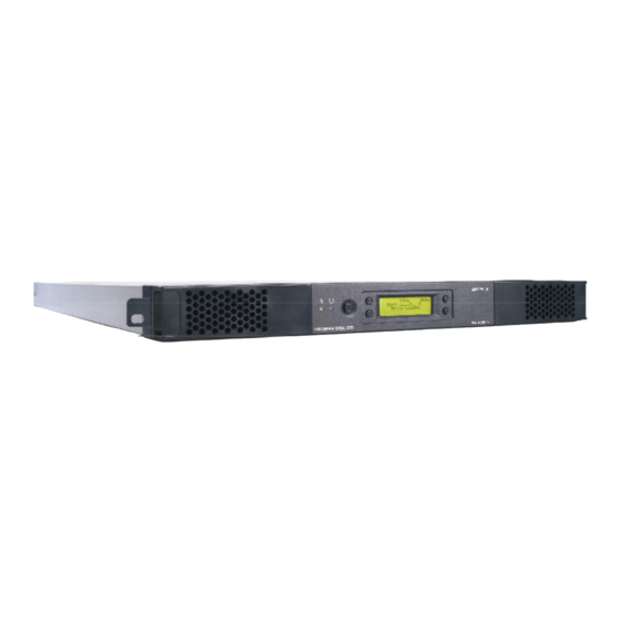
- Page 5 Tandberg Data Remote Management Table of Figures Figure 2.1 Overview of Tandberg Data StorageLoader 1U ... 7 Table 2- 1 Data Storage Capacity ........ 8 Table 2- 2 Data Transfer Rates ........8 Figure 2.2 Front panel of the StorageLoader ..... 9 Figure 2.3 Internal components of the StorageLoader ..
- Page 6 Tandberg Data About This Manual Figure 5.3 Remote Management Status Page ....52 Figure 5.4 Remote Management Command Page ..... 54 Figure 6.1 Transport lock marked with red plastic tab ..58 Figure 6.2 Field Replaceable Units ......... 60 Figure 6.3 Replacing the tape drive ....... 61 Figure 6.4 Rear of the tape drive........
-
Page 7: About This Manual
List of spare parts and accessories ....92 1. About This Manual This m anual describes how t o inst all and use t he Tandberg Dat a St orageLoader for 420LTO and DLT VS160 t ape drives. I t is int ended for use by anyone who would inst all, use and m aint ain the device. -
Page 9: General Information
The loader can be m ount ed in a 19” rack or used as a t ablet op unit. Its height is 1U. The loader is equipped wit h a Tandberg DLT VS160, 220LTO or 420LTO tape drive and has room for 8 cartridges in two 4- cartridge magazines. -
Page 10: Models
Tandberg Data Operation and Configuration *** IMPORTANT *** Review the READ ME FIRST caution at the beginning of Chapter. 3 before you power up the unit for the first time. Models.For addit ional specificat ion inform at ion t his model, refer to Appendix A. -
Page 11: Front Panel
Tandberg Data Operation and Configuration An Et hernet connect ion allows for m anagem ent by an operat or wit h st andard browser rem ot e com put er. rem ot e operat or m ost t he operat ions t hat can be done t hrough t he front panel, such as m onit oring t he loader’s st at us and downloading st at ist ical... - Page 12 Tandberg Data Operation and Configuration any activity is always visible on the display. LED Indicators The t wo LED indicat ors are green and am ber. They indicat e t he StorageLoader activity as follows: Green LED on: The St orageLoader is eit her running or ready for operation.
-
Page 13: Internal Components
Tandberg Data Operation and Configuration Internal Components The St orageLoader feat ures t he m ain int ernal com ponent s shown in the figure below. Drive Slot 4 Power Supply Slot 3 Cartridges Slot 8 Slot 2 Robotics module... -
Page 14: Figure 2.4 Cartridge Magazines
Tandberg Data Operation and Configuration Cartridge Magazines There are t wo rem ovable m agazines ( FRUs) , each holding four t ape cart ridges, see figure 2.4. The m agazine includes design features to ensure that cartridges are always inserted correctly and stay securely seated. -
Page 15: Rear Panel
Tandberg Data Operation and Configuration 2.2.2 Rear Panel The figure below shows the rear panel of the StorageLoader. Main Fuse Power cord Back panel SCSI Ethernet Power connection cover plate connectors port switch Figure 2.5 Rear panel of the StorageLoader... -
Page 16: Installation
A fact ory- assem bled St orageLoader unit cont aining t wo cartridge magazines. A Standard Accessory Kit containing: - 1 The Tandberg Dat a St orageLoader CD cont aining all manuals - 1 Printed copy of the Quick Installation Guide - 1 Warranty/Registration Card... - Page 17 Tandberg Data Operation and Configuration - 2 Line Power Cords: one for USA/ Japan and one for European power outlets - 1 VHDCI SCSI Interface Cable - 1 68- pin VHDCI LVD/SE SCSI Terminator. - 1 Ethernet cable - Tool for Emergency Magazine Release - 30 StorageLoader specific Bar code labels There will be variat ions of t his list .
-
Page 18: Figure 3.1 Rack Mounting Kit
Tandberg Data Operation and Configuration Folding rule or tape measure Screwdriver 7 mm open- end wrench Note: The rails are m ount ed t o t he loader during t ransport at ion. Before mounting the rails into the rack, dismount the rails from the loader and remove the spacers between the rails and the loader. -
Page 19: Figure 3.2 Rack Mount Rail
Tandberg Data Operation and Configuration St orageLoader 1U uses 1U of vert ical rack space. The rails m ust be inst alled in a full U posit ion ( The bot t om of t he rails m ust be aligned wit h t he bottom of a U), see figure 3.2. -
Page 20: Figure 3.3 Mounting The Rack Mounting Kit To A Rack
Tandberg Data Operation and Configuration Use these holes if rack depth is Step 1 equal or longer Holes to be than the used if rack StorageLoader depth is shorter Rear Rack than the Mount Rail StorageLoader Step 5 (Screw M6x12) -
Page 21: Figure 3.5 Slide The Storageloader In From The Front
Tandberg Data Operation and Configuration Slide t he St orageLoader on t he rails from t he front of t he rack, as shown in figure 3.5. Then fix t he St orageLoader using one M6x12 screw in front of t he rack on bot h left and right side ( see figure 3.6) and one M5x8 on t he backside of t he Rack Mount ing Kit on... -
Page 22: Figure 3.8 Main Power Switch, Fuse Holder And Power Cord Connection
Tandberg Data Operation and Configuration Step 3. Connecting Power Cable The StorageLoader is offered both with AC and DC connection. - DC connection. This version is offered wit h special connect or and - 48 VDC voltage. This is described in appendix. -
Page 23: Figure 3.9 Robotics Lock Marked With Red Plastic Tab
Tandberg Data Operation and Configuration Step 4. Removing the Transport Lock The robot m echanism prot ect ed from dam age during shipm ent wit h screw holding t he robot ics in a locked position. This locking screw is... - Page 24 Tandberg Data Operation and Configuration problem occurs during t he power- on sequence, t he St orageLoader will display an error m essage on t he display. Refer t o chapt er 4.2 and 7, t o learn t he procedures for resolving t he problem.
-
Page 25: Figure 3.10 Scsi Cable And Scsi Terminator Connection
Tandberg Data Operation and Configuration D) Before t he St orageLoader is powered on and t he syst em is rest art ed, m ake sure t hat t he SCSI properly t erm inat ed. I f t he St orageLoader t erm inat es t he SCSI bus, it... -
Page 26: Figure 3.11 Positioning Of Bar Code Label For Lto Cartridges
Tandberg Data Operation and Configuration 2. Connect t he ot her end t o a norm al 10/ 100 BaseT Et hernet outlet. The Et hernet - based Rem ot e m anagem ent syst em is described in chapter 5, Remote Management. -
Page 27: Figure 3.12 Positioning Of Bar Code Label For Dlt Cartridges
Tandberg Data Operation and Configuration Figure 3.12 Positioning of bar code label for DLT cartridges. StorageLoader Installation and User Manual... -
Page 28: Operation And Configuration
Tandberg Data Operation and Configuration 4. Operation and Configuration The Local User I nt erface ( LUI ) consist s of a sm all LCD panel capable of displaying four lines of 20 charact ers each, and four cont rol but t ons, one near each corner of t he display. The but t ons have soft labels in t he corners of t he display. -
Page 29: Figure 4.3 The Default Screen
Tandberg Data Operation and Configuration Default screen, see figure 4.3 appears and t he loader is ready for SCSI commands. The Map of the cartridges has the following symbols: 1. A “?” when status is unknown and Inventory is still running. -
Page 30: Table 4- 2 Drive Operation Statuses
Tandberg Data Operation and Configuration The Drive Status line (line 3) can show the following status: Drive Empty There is no cartridge in the drive Drive Loaded A Cartridge is Loaded. Drive Idle A Cart ridge is loaded and t he... -
Page 31: Front Panel Display Modes
Tandberg Data Operation and Configuration 4.2 Front Panel Display Modes The front panel displays t hree t ypes of screens for different purposes: the Menus, the Dialogs and the Messages. 4.2.1 Menus The m aj or cont ribut or is t he MENU. I t is used t o select operat ions t o perform by enabling t he operat or t o navigat e a m enu t ree using the control buttons. -
Page 32: Figure 4.5 The Complete Menu Tree
Tandberg Data Operation and Configuration Figure 4.5 The Complete Menu Tree StorageLoader Installation and User Manual... -
Page 33: Dialogs
Tandberg Data Operation and Configuration 4.2.2 Dialogs A dialog is a screen t ype used t o get det ailed input from t he operat or, for exam ple a SCSI I D, a nam e or a password. See Figure 4.6. -
Page 34: Figure 4.8 Slot Dialog Layout
Tandberg Data Operation and Configuration Examples: If the value “0” or “1” is selected in the Fixed IP address dialog above, the user is allowed to select values between “0” and “9” as the next two digits. (The maximum value allowed in this dialog is “255”... -
Page 35: Messages
Tandberg Data Operation and Configuration Here, t he user can scroll t hrough a set of opt ions one at a t im e by using t he left and right arrow but t ons. Only one opt ion is shown at a t im e. -
Page 36: Main Menu
Tandberg Data Operation and Configuration 4.3 Main Menu The Main m enu cont ains a set of frequent ly used funct ions and links to a set of sub menus. Item name Description Load to Loads a cartridge from a selected magazine slot into Drive the drive. -
Page 37: Setup Menu
Tandberg Data Operation and Configuration Utilities Selects a set of the loader and drive maintenance and diagnostic functions. The loader must be idle to make this entry selectable. See chapter Utilities Menu for more details. The Main m enu can be select ed even if t he loader is not in t he idle st at e. -
Page 38: Scsi Setup
Tandberg Data Operation and Configuration 4.4.2 SCSI Setup The SCSI set up m enu allows select ion of SCSI addresses for bot h t he Loader and it s int ernal drive. I n addit ion, t he SCSI bus Parit y can be enabled or disabled. -
Page 39: View Data Menu
Tandberg Data Operation and Configuration * Used only while the IP address assignment is in Static mode. 4.4.3.1. Remote Management Access Control Item name Legal values. Default value Allow Remote Allowed, Not allowed Allowed Management Allow Remote FW Allowed, Not allowed... -
Page 40: Drive Info
Tandberg Data Operation and Configuration Cleaning Slot Defined cleaning slot, Disabled Disabled Barcode Reader Enabled, Disabled Enabled if installed, else Disabled Loader Serial Loader Serial number. Loader FW StorageLoader FW id xx.yy revision and revision Loader Vendor Current Inquiry Vendor “TANDBERG”... -
Page 41: Remote Management Info
Tandberg Data Operation and Configuration 4.5.3 Remote Management Info The Rem ot e Managem ent ( RMM) set up is shown in t he choices list ed below. This m enu t hree is t he place t o find t he current ly allocat ed dynam ic I P address, default gat eway and net work m ask when running in DHCP m ode. -
Page 42: The Maintenance Menus
Tandberg Data Operation and Configuration Diagnostics Displays a list of exercise test programs Access control Set Password 4.6.1 The Maintenance Menus Item name Description Prepare to When selected the robotics will be positioned for Ship installation of the locking screw. -
Page 43: Set Password
Tandberg Data Operation and Configuration 4.6.3 Set Password Item name Description Set Password Allows the operator to set a four- digit password protection for the menu system. The default password is <0000>, meaning the password is disabled. WARNING: If you set a password, make sure you do not forget it. If you do, it ca n on ly be cle a r e d w it h a ssist a n ce fr om Ta n dbe r g D a t a t e ch n ica l support or by a qualified service technician. -
Page 44: Magazine Handling
Tandberg Data Operation and Configuration 3. Press the Ok button. The robot rem oves t he cart ridge from t he select ed m agazine slot and moves it to the drive. To unload a cartridge from drive: 1. From t he default display, press t he m enu but t on and select Unload from Drive from t he m ain m enu. -
Page 45: Figure 4.14 Removing Magazine
Tandberg Data Operation and Configuration Note: You cannot rem ove t he m agazine if t he unit is password prot ect ed or locked by host soft ware t hrough a Pr e ve nt M e dium Removal SCSI command. -
Page 46: Inserting Cartridges Into The Magazine
Tandberg Data Operation and Configuration hand under t he m agazine t o prevent t he back of t he m agazine t o fall down when it leaves the magazine bay. See illustration below. Figure 4.16 Removing the magazine from the loader 4.8.2 Inserting Cartridges into the Magazine... -
Page 47: Inserting A Magazine Into The Unit
Tandberg Data Operation and Configuration cart ridge is released. The cart ridge is spring loaded so it is im port ant t o prevent t he cart ridge from popping all t he way out . If t he cart ridge falls down, it m ay be dam aged and dat a m ay be lost. -
Page 48: Manual/Emergency Release Of Magazines
Tandberg Data Operation and Configuration 4.8.5 Manual/Emergency Release of Magazines I n case of failure sit uat ions eit her in t he loader it self, a power loss, or if you want t o m anually release t he m agazines for som e ot her reason, a m anual/ em ergency release is available. - Page 49 Tandberg Data Operation and Configuration 1. Finish possible StorageLoader activity. 2. Cont rolled abort ing of t ape drive act ivit y; buffered dat a is flushed t o t ape; cart ridge is unloaded from drive but not ejected.
-
Page 50: Remote Management
5. Remote Management I n order t o facilit at e Rem ot e Managem ent , t he St orageLoader is equipped wit h an Et hernet int erface and a built in web server. The Rem ot e Managem ent I nt erface ( RMI ) can be accessed wit h a standard web browser, such as Internet Explorer, Mozilla or Opera. -
Page 51: Remote Management Web
Tandberg Data Maintenance 2.1. I f you want t o use a st at ic I P address, use t he front panel t o ent er a valid st at ic I P configurat ion, see sect ion 4.4.3, Remote Management setup. -
Page 52: Storageloader Start Page
Tandberg Data Maintenance Drive inform at ion cont aining t echnology, serial num ber, firmware version and activity. 5.2.2 StorageLoader Start Page Aft er successfully connect ing t o t he St orageLoader from your browser, you will see t he St orageLoader St art page, figure 5.2. -
Page 53: Status Page
Tandberg Data Maintenance Figure 5.2 Remote Management Start Page Note: St orageLoader net work t raffic is not encrypt ed, so anyone wit h physical access t o t he net work pat h will be able t o access t he... -
Page 54: Figure 5.3 Remote Management Status Page
Tandberg Data Maintenance Figure 5.3 Remote Management Status Page The figure provides an updat ed st at us of drives, robot ics and cartridges using color- coding and symbols. The Drive and Robot st at us will be shown as a green ( OK) , yellow ( Warning) or red ( Error) dot . -
Page 55: Settings
Tandberg Data Maintenance I f you click on a slot , addit ional cart ridge inform at ion will be shown in a pop up window. This inform at ion includes t he cart ridge barcode ( if label and barcode reader is inst alled) and t he error code. -
Page 56: Command Page
Tandberg Data Maintenance 5.2.5 Command Page On t his page it is possible t o m ove cart ridges bet ween m agazine slot s and drive. All cart ridges in t he St orageLoader will be found in a pull- down list sort ed by locat ion. The ot her pull- down list shows the empty locations where it is possible to move the cartridge to. -
Page 57: Maintenance
Debugging Mem ory dum p will download a snapshot of t he syst em m em ory of t he loader t o a file t hat can be sent t o Tandberg Data’s service for diagnostic purposes. Perform a system reset. -
Page 58: Removing The Cleaning Cartridge
Tandberg Data Maintenance c. a cartridge in the slot defined as the cleaning slot. If all of the above fails, the loader will display a dialog asking the operator for the slot to fetch the cleaning cartridge from. 3. While the cleaning operation is on- going, the display shows the drive status “Drive Cleaning”. -
Page 59: Installing Firmware Upgrades
Tandberg Dat a sit e http://www.tandberg.com/. The program is available for Win XP, Win 2000/2003, Win Nt. Note: Read this entire procedure before you perform an upgrade. 1. I nst all t he FlashI t ut ilit y t hat is designed for your operat ing... -
Page 60: Possible Upgrade Problems
Tandberg Data Maintenance flashes in addit ion t o t he Am ber LED being lit . The program m ing operat ion takes less than one minute. 9. When reprogram m ing is com plet ed, t he loader will do a normal reboot I f t he firm ware upgrade operat ion failes during point 8 due t o a power shut- down or similar, the loader may require service. -
Page 61: Transport Lock Installation Procedure
Tandberg Data Maintenance installed. The t ransport lock m ust be rem oved prior to operation. 6.4.1 Transport Lock Installation Procedure To insert the locking screw do the following: 1. If there is a cartridge in the drive, unload the drive first. -
Page 62: Fru Drive Tray Assy Dlt Vs160 Scsi
Tandberg Data Maintenance Figure 6.2 Field Replaceable Units 6.5.1 FRU Drive Tray Assy DLT VS160 SCSI This VS160 drive FRU consists of the following parts: 006978 StorageLoader FRU Drive Tray Assy DLT VS160 Item Part Description 006957 DLT VS160 Bare Drive... -
Page 63: Figure 6.3 Replacing The Tape Drive
Tandberg Data Maintenance For replacing the tape-drive, switch off the loader, disconnect the power cord and remove these two screws and the back-panel cover plate. Figure 6.3 Replacing the tape drive You now have access to the rear of the tape-drive and can dismount the SCSI cable, the ADI cable and the power cable. -
Page 64: Figure 6.6 Guide Cartridge Mounting
Tandberg Data Maintenance After removing the defective drive, the drive mounting brackets on both sides of the drive must be removed from the drive, since these will be used for mounting the replacement- drive. The drive mounting brackets are fastened with two screws each. -
Page 65: Fru Drive Tray Assy 420Lto
Tandberg Data Maintenance Snap the front bezel that was removed from the replacement- drive onto the front of the defective drive. Then pack the defective drive in the same box you received the replacement- drive and return it to your support center. -
Page 66: Figure 6.9 Rear Of The Tape Drive
Tandberg Data Maintenance You now have access to the rear of the tape-drive and can dismount the SCSI cable, the ADI cable and the power cable. Power cable ADI cable SCSI cable Figure 6.9 Rear of the tape drive Release the tape-drive by... -
Page 67: Fru Power Supply
Tandberg Data Maintenance drive and the brackets laying on a level surface to ensure the brackets are aligned with the bottom of the drive. Fasten the brackets with two screws each. Insert the replacement drive carefully into the loader the same way it was removed, reconnect the 3 cables (the ADI cable is mounted closest towards the SCSI cable) and re- mount the back plate. -
Page 68: Fru Fan
Tandberg Data Maintenance supply and carefully unhook t he connect ors for power and fan ( Figure 6.13) before com plet ely rem oving t he power- supply module. Fan power cable Power connector Figure 6.13 Fan power Aft er rem oving t he power- supply, insert t he replacem ent unit carefully t he sam e way, reconnect t he 2 cables, fast en t he fixing screw and re- m ount t he back plat e. -
Page 69: Figure 6.15 Removing The Fan
Tandberg Data Maintenance Figure 6.15 Removing the fan Rem ove t he fan fixing screws ( Figure 6.15) . Unhook t he power connect or of t he fan and carefully replace it . When re- insert ing t he fan t ake care t o have t he cable in t he not ch in t he chassis. -
Page 70: Fru Magazine
Tandberg Data Maintenance 6.5.5 FRU Magazine The FRU Magazine for t he LTO version consist s of t he following parts: LTO Magazine FRU StorageLoader 1U Part no Description S80873 Magazine Left LTO S80873 Magazine Right LTO The FRU Magazine for t he DLT version consist s of t he following... -
Page 71: Fru Filter
Tandberg Data Maintenance 6.5.6 FRU Filter This FRU consists of the following parts: S808741 Filter FRU StorageLoader 1U Item Description Filter Quick Installation Guide Filter When needed, t he dust filt er can be pulled out and a new one slid int o t he front - bezel assem bly of t he m agazines. -
Page 73: Troubleshooting
Tandberg Data Maintenance 7. Troubleshooting 7.1 How to Take Memory Dumps of the Loader 1. Log in to the remote management interface as Administrator. 2. Navigate to Maintenance Debugging. 3. Click “Memory dump”. 4. Select “Save to disk” in the file download dialog box. -
Page 74: Software Checking
Tandberg Data Maintenance on ot her devices at t ached t o t he sam e SCSI bus and t heir SCSI I Ds, you m ay need t o change t he SCSI I D of t he t ape drive or autolaoder before you can use the autoloader. -
Page 75: Trouble Shooting Matrix
Tandberg Data Maintenance I f t he aut oloader has been inst alled previously and operat ing correctly but is now incurring a problem, verify any recent changes to t he syst em t o ensure t hat t hese changes are not causing t he problem. - Page 76 Tandberg Data Maintenance The front panel does not display • Power cycle the loader by turning off and on the main information but the back light on power switch on the rear of the loader. the front panel is on •...
- Page 77 Tandberg Data Maintenance Cartridge stucked in drive • Power cycle the loader by turning off and on the main power switch on the rear of the loader. Allow both the loader and the drive to complete initialization, which in rare cases can take as long as 10 minutes, and then retry unloading the tape using the autoloader operator panel controls.
- Page 78 Tandberg Data Maintenance Data cartridge incompatible with • Make sure you are using a data cartridges that is drive compatible with the drive. See the tape drive’s reference manuals for details. • The SW backup application detects if an incompatible data cartridge is used, and communicates this to the user.
- Page 79 Tandberg Data Maintenance StorageLoader Installation and User Manual...
- Page 80 Tandberg Data Maintenance The tape loader responds on • Verify that a SCSI terminator is attached to both the last the SCSI bus to the host, but and first SCSI device on the SCSI bus. the tape drive does not respond •...
- Page 81 Tandberg Data Maintenance Write or read issues Contaminated head Avoid contamination by ensuring that the autoloader is installed in a clean, contamination-free environment. Cartridges should be stored vertically in their plastic cases. Continue cleaning the tape drive as needed. If a cleaning cartridge is not successful in resolving the problem after 3 or more attempts, the cleaning cartridge may be contaminated and should not be used in another drive.
-
Page 82: The Error Screen
Tandberg Data Maintenance Forgot password on FPI • Look up the RMI IP address from the front panel menu (view data menu). • Connect the RMI interface and perform a memory dump of the loader (see user and installation guide for details). -
Page 83: Figure 7.2 Example Of Detailed Information
Tandberg Data Maintenance Figure 7.2 Example of detailed information If the problem persists please call technical support. Back Figure 7.3 Example of further detailed information In this example, pressing “Back” twice takes you back to the Error Code Page (figure 7.1) where you can press “Actions” to go to the Actions menu. -
Page 84: Error Codes
Tandberg Data Maintenance 7.8 Error Codes The error codes are listed in numerical sequence by their Fault Symptom Code (FSC) in the tables that follow. If a persistent error condition prompts you to call your Technical Support representative, be sure to supply the code information to help identify the problem. - Page 85 Tandberg Data Maintenance 1209 Failed to fetch at Failed to eject 1. Reboot the loader and retry the Defect drive or slot 09 cartridge from operation. robotics. Defect drive 2. Try to eject the cartridge from cartridge. the drive via the front panel menu.
-
Page 87: Appendix A - Specifications
Appendix A – Specifications A.1 Mechanical Dimensions and Weight The Tandberg Dat a St orageLoader 1U is designed as a rack m ount unit. The StorageLoader can also be used as a tabletop unit. Dimensions: Length 740 mm (29.13 in) 0.5 mm from front rail to... -
Page 88: Power Requirements
Tandberg Data Spares/Accessories A.2 Power Requirements Normal AC version. Input voltage 90 VAC – 264VAC Input Frequency 47 Hz – 63 Hz Inrush Current (Cold Start) Less than 30 A, 115VAC Less than 60 A, 230 VAC Power consumption average... - Page 89 Tandberg Data Maintenance Notification. Ref. UL60950- 1: StorageLoader Installation and User Manual...
- Page 90 Tandberg Data Spares/Accessories Special DC connector: StorageLoader Installation and User Manual...
-
Page 91: Vibration Specifications
Tandberg Data Maintenance A.3 Vibration Specifications Sinusoidal sweep Sweep Rates 1 octave/minute Axes X, Y and Z Duration 2 hours Frequency Range Level (Hz) Operating 24.2 0.01 in p- 24.2 0.3g Non- Operating 27.1 0.02 in p- (Storage) 27.1 0.75g Transport 0.5g... -
Page 92: Mechanical Shock Specifications
Tandberg Data Spares/Accessories A.4 Mechanical Shock Specifications Mechanical Bump/Shock Axes X, Y, Z Directions Positive and negative Pulse 3 seconds interval Pulse Pulse Pulse Pulses/axis/direction shape duration Level Operating Half sine 5ms 1000 Storage Half sine 8ms (X,Z) Storage (Y) -
Page 93: Noise Specification
Tandberg Data Maintenance Table A - 8 StorageLoader humidity specification Altitude Operating Range - 500 to 10000 ft Non- Operating Range - 500 to 40000 ft Table A - 9 StorageLoader altitude specification A.7 Noise Specification Acoustic Idle (L 60 dBA... -
Page 94: Table B - 1 List Of Spare Parts And Accessories
Tandberg Data Spares/Accessories Type Description Accessories Accessory kit DLT 800246 Accessory kit LTO 870157 Quick Installation Guide 433060 Table B - 1 List of spare parts and accessories StorageLoader Installation and User Manual...
Need help?
Do you have a question about the STORAGELOADER and is the answer not in the manual?
Questions and answers